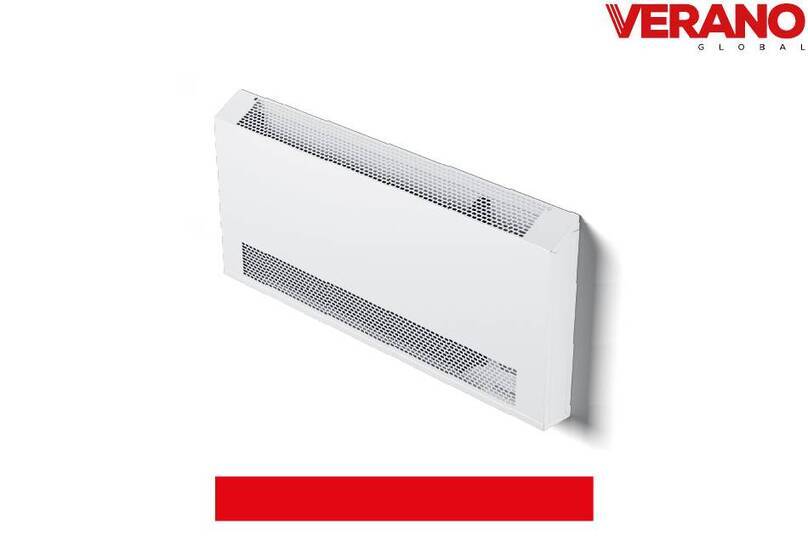
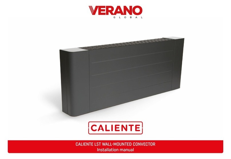
Verano LVKN2 User manual
Other Verano Heater manuals
Popular Heater manuals by other brands

Porter-Cable
Porter-Cable PCXH80KT Operating instructions and owner's manual

Dyna-Glo
Dyna-Glo RA18LPDG user manual

Dimplex
Dimplex PLX050E instruction manual

EOS
EOS Herkules XL S120 installation instructions

Trebs
Trebs Comfortheat 99209 manual

Biddle
Biddle STYLE2 Series Installation operation & maintenance

Vermont Castings
Vermont Castings Non-Catalytic Convection Heater 2477CE Installation and operating manual

Fagor
Fagor RA-1505 Instructions for use

THERMAL FLOW
THERMAL FLOW Delta 175 Operating instructions manual

GET
GET G2CH instructions

ApenGroup
ApenGroup PK Series User, installation, and maintenance manual

oventrop
oventrop Regucor Series quick start guide

Blaze King
Blaze King CLARITY CL2118.IPI.1 Operation & installation manual

ELMEKO
ELMEKO ML 150 Installation and operating manual

BN Thermic
BN Thermic 830T instructions

KING
KING K Series Installation, operation & maintenance instructions

Empire Comfort Systems
Empire Comfort Systems RH-50-5 Installation instructions and owner's manual

Well Straler
Well Straler RC-16B user guide


