VERDER Carbolite Gero EVT 12/450B Manual

Installation, Operation and Maintenance Instructions
1200°C E-Range Tube Furnace - EVT Model: 450mm
No Controller
EVT 12/450B + No Controller
MEN-EVT12450B-005_NOCTRL (30-01-2018)

Contents
This manual is for guidance on the use of the Carbolite Gero product specified on the
front cover. This manual should be read thoroughly before unpacking and using the
furnace or oven. The model details and serial number are shown on the back of this
manual. Use the product for the purpose for which it is intended.
1.0 Symbols and Warnings 4
1.1 Switches and Lights 4
1.2 General Warnings 4
1.3 Warning Labels 5
1.3.1 - Control Box layout and warning labels. 6
1.3.2 - Back of control box showing mains lead socket 6
2.0 Installation 7
2.1 Unpacking and Handling 7
2.2 Siting 7
2.3 Setting Up 7
2.3.1 Figure - Vertical tube furnace model mounted on its stand. 9
2.3.2 Figure - Assembling the stand. 9
2.3.3 Figure - Mounting the furnace onto the vertical stand. 9
2.3.4 Figure -Tube furnace positioned horizontally on the stand. 10
2.3.5 Figure - Tube support 11
2.3.6 Figure - Tube support assembled 11
2.3.7 Figure - Tube support and end seal 12
2.3.8 Figure - Tube support and end seal assembly 12
2.3.9 Figure - View showing how to support the work tube in a vertical ori-
entation. 13
2.4 Setting Up - Without a Stand 13
2.4.1 Figure - Tube furnace shown without a stand for customers own mount-
ing as an example. 13
2.4.2 Figure - Cross-section view showing standard length work tube insu-
lation plug fitted 14
2.4.3 Figure - Cross-section view showing extended work tube insulation
plug fitted 14
2.4.4 Figure - Cross-section view showing an extended length work tube with
a radiation shield fitted 14
2.5 Electrical Connections 15
3.0 Temperature Controller 16
4.0 Operation 17
4.1 Operating Cycle 17
2

4.2 Safe Operation of the Furnace 17
4.3 General Operating Advice 18
4.4 Operator Safety 18
4.5 Tube Life 19
4.6 Pressure 19
4.7 Gas Tightness 19
5.0 Maintenance 20
5.1 General Maintenance 20
5.1.1 Cleaning 20
5.2 Calibration 20
5.3 After-Sales Service 20
5.4 Recommended Spare Parts and Spare Parts Kit 20
6.0 Repairs and Replacements 21
6.1 Safety Warning - Disconnection from Power Supply 21
6.2 Safety Warning - Refractory Fibre Insulation 21
6.3 Temperature Controller Replacement 21
6.4 Solid-state Relay Replacement 22
6.5 Thermocouple Replacement 22
6.6 Element Replacement 22
6.7 Fuse Replacement 23
7.0 Fault Analysis 24
A. Furnace Does Not Heat Up 24
B. Product Overheats 25
8.0 Wiring Diagrams 26
8.1 WA-11-30 26
8.2 WA-11-70 27
9.0 Fuses and Power Settings 28
9.1 Fuses 28
9.2 Power Settings 29
10.0 Specifications 30
10.1 Environment 30
Furnace drying out process 31
3

1.0 Symbols and Warnings
1.1 Switches and Lights
Instrument switch: when the instrument switch is operated the
temperature control circuit is energised.
Heat light: the adjacent light glows or flashes to indicate that power
is being supplied to the elements.
Heat switch: the switch disconnects power to the heating elements;
unless this switch is OFF there is a danger of electric shock when
inserting objects into the product.
1.2 General Warnings
DANGER – electric shock. Read any warning printed next to this
symbol.
WARNING: risk of fatal injury.
DANGER – hot surface. Read any warning printed next to this
symbol.
WARNING: all surfaces of a product may be hot.
DANGER – read any warning printed next to this symbol.
4

Caution – Double Pole/Neutral Fusing
1.3 Warning Labels
On the front control panel there are 2 warning labels as shown in Figure 1.3.1; they are
numbered 7 and 8. These warnings must be followed for the safe operation of this
furnace.
7- Warning label - Do not operate without a work tube.
The furnace must not be operated without the correctly sized work tube
and correspond work tube adaptors or it could be possible for an
operator to access electrically live element coils that could cause serious
injury or death.
8- Warning label - Switch off the furnace before loading and
unloading.
The furnace heaters must be switched OFF using the heater switch, item
2 in Figure 1.3.1, when the furnace is being loaded or unloaded. The
work tube can become electrically conductive at high temperatures,
presenting a possible hazard to the operator. If element failure is left
undetected the element could collapse onto the work tube.
5
1.0 Symbols and Warnings

1.0 Symbols and Warnings
Index to numbered items in Figure 1.3.1
and 1.3.2
1. Electrical supply switch - switches
electrical power ON and OFF to the
furnace.
2. Heater switch - switches electrical
power ON and OFF to the furnace
heating elements.
3. Heater ON light - indicates that the
furnace heating elements are ener-
gized.
4. Product rating label indicating the
product serial number and electrical
information.
5. Access holes to front panel fixing.
6. Warning label - Disconnect the
mains supply before removing this
cover.
7. Warning label - Do not operate
without a work tube.
8. Warning label - Switch OFF the fur-
nace before loading and unloading.
9. Electrical power lead socket.
10. Back panel fixing screws.
1.3.1 - Control Box layout and warn-
ing labels.
1.3.2 - Back of control box showing
mains lead socket
6

2.0 Installation
If the product has been transported or stored in humid conditions it
must be dried out completely before operating the furnace. Contact
Carbolite Gero Service for instructions.
2.1 Unpacking and Handling
When unpacking or moving the product, always lift it by its base or both ends of the
main body. Never lift it by the end insulation or by a work tube. It may take 2 or 3
people to lift the furnace, depending on the size and configuration.
NOTE: This product contains Refractory Ceramic Fibre (also known as
Alumino Silicate Wool - ASW). For precautions and advice on handling
this material see section 6.2.
2.2 Siting
Place the product on a level surface in a well ventilated area. Site away from other
sources of heat and on a non-flammable surface that is resistant to accidental spillage
or hot materials.
The surface on which the equipment is mounted should be stable and not subject to
movement or vibrations. The height of the mounting surface is important to avoid
operator strain when loading and unloading samples.
Ensure that there is free space around the sides and back of the product. Clear space is
required above the product to dissipate heat.
If the product is to be used in a process which could liberate hazardous gases, then it
should be installed together with a suitable fume extraction system.
Ensure that the product is placed in such a way that it can be quickly switched off or
disconnected from the electrical supply.
2.3 Setting Up
The vertical tub furnace models must have their stands assembled, the furnace
mounted on the stand and their work tubes fitted before they can be used.
Assembling the stand and mounting the furnace
Tools required: 4 mm Allen key.
The assembly of the vertical stand is as follows with reference to 2.3.1, 2.3.2 and 2.3.3.
Place the vertical stand base item (1) on the floor or bench on which it is to be
assembled.
7
2.0 Installation

2.0 Installation
lPosition the vertical stand upright (2) on the stand base in line with the fixing holder.
lSecure the stand upright to the base using the 6 x M6 dome cap screws (4) and wash-
ers (3) supplied.
lPartially screw in the top M6 screw knobs, 2 x (6) into the frame upright as shown in
2.3.3.
lHook the furnace onto the top screw knobs. This may take 2 people to lift the fur-
nace.
lFit the bottom screw knobs x 2 and tighten all four.
8

2.3.1 Figure - Vertical tube furnace model
mounted on its stand.
2.3.2 Figure - Assembling the
stand.
Index to numbered items in Figure 2.3.2 and
Figure 2.3.3
1. Vertical stand base
2. Vertical stand upright
3. Fixing screws M6 x 16 dome cap screw
4. Washer M6
5. Tube furnace
6. M6 screw knob
2.3.3 Figure - Mounting the fur-
nace onto the vertical stand.
9
2.0 Installation

2.0 Installation
Using the tube furnace horizontally
The furnace can be used either with the stand
vertically as shown in 2.3.3 or horizontally as
shown in 2.3.4.
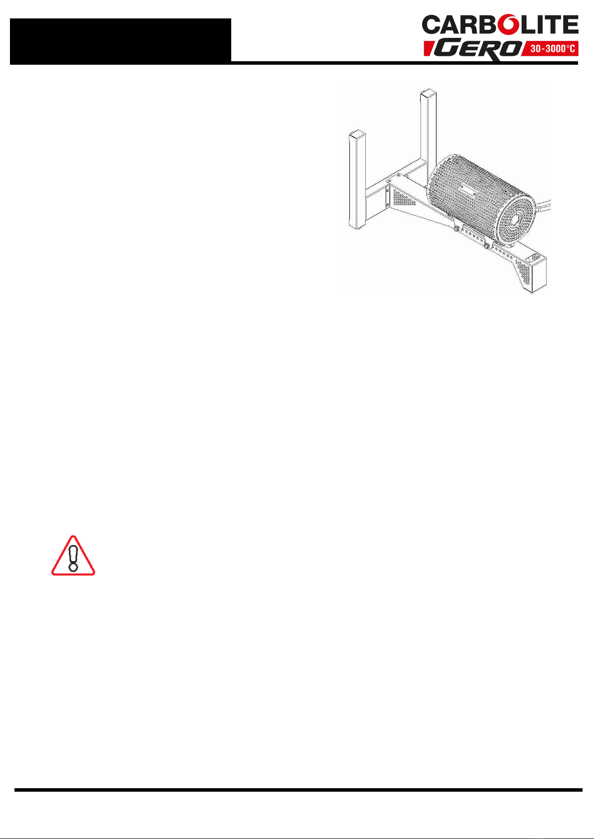
To use horizontally simply tip the stand over
into the horizontal position making sure that
the flexible conduits are not trapped beneath
the frame. This may take 2 people to do on
the largest models.
The position of the furnace on the stand can
be adjusted if necessary.
Note: To prevent injury to the operator and
damage to the furnace this must only be
done when the furnace is switched OFF and is
cold. 2.3.4 Figure -Tube furnace posi-
tioned horizontally on the stand.
Note that the split tube furnace can only be used with the extended length work tube.
Fitting the extended work tube in a furnace
Tools required: 4 mm Allen key
The fitting of the work tube is as follows with reference to Figure 2.3.8. Extended work
tubes are 450 mm longer than the heated length of the furnace (see the table in section
10.0). Read section 6.2 before fitting the work tube.
Note it is easier to fit the work tube with the furnace in the horizontal position as shown
in figure 2.3.4.
To fit the work tube in a vertical orientation follow the steps below. Omit the use of the
end seal if not required. The same tube support design will work with or without the
tube end seal in place.
WARNING - If clamps are used without an end seal, care should be
taken not to over tighten on to a bare tube, especially if the tube is
either quartz or thin wall thickness.
lBefore the extended work tube can be fitted, the work tube end stops for the stand-
ard length work tube must be removed from both ends of the furnace. This is done
by removing the tube furnace end guard (8) and the work tube adaptor brackets (4)
to release the work tube end stop. The guards and brackets should then be refitted.
lFit the tube support bracket, item 15, figure 2.2. Use supplied M6 button head
screws and supplied washers.
lFit the extended work tube guard, item 14, figure 2.2. Use supplied M6 button head
screws and supplied washers.
lRe-fit furnace end guard, item 13, figure 2.2. Use supplied M6 button head screws
and washers.
lFit tube end seal assembly as shown in figure 2.2. refer to manual that was provided
with the replacement end seals or detailed fitting instructions.
10

lFit tube support bracket, item 7, figure 2.2. Use supplied M6 button head screws and
washers.
lFinally, fit tube support collar, (5) using item (6) until the tube is secure enough for
use in a vertical arrangement. Fitting arrangement is shown in figure 2.2.
lFigure 2.2 - shows an exploded view of all the required parts.
lFigure 2.2 - shows the assembled parts as they would be used.
2.3.5 Figure - Tube support
2.3.6 Figure - Tube support assembled
11
2.0 Installation

2.3.9 Figure - View showing how to support the work tube in a vertical orientation.
2.4 Setting Up - Without a Stand
Any of the E-range vertical furnaces can be supplied without a stand for either wall
mounting (using wall bracket option) or installation in customer's test rig/mounting
frame.
It is the customer’s responsibility to carry out a risk assessment on the
siting and mounting of the furnace and to ensure that it is operated in a
safe manner, see section 2.2 for the recommended siting instructions.
The fitting of the work tube is covered in the previous section.
2.4.1 Figure - Tube furnace shown without a stand for customers own mounting as
an example.
Index to numbered items in Figure 2.4.1
1. Control Box
2. Furnace Body
13
2.0 Installation

2.0 Installation
3. Connecting conduit between furnace and control box
Fitting the Optional Insulation Plugs and Radiation Shield
For optimum temperature uniformity, insulation plugs or radiation shields should be
placed in the work tube ends as shown below. With a standard work tube, the stem (8)
(see figure 2.4.2) of the insulation plug assembly lines up with the end of the work tube.
If a gas/vacuum end seal is fitted, either horizontally or vertically, the insulation plug
hooks onto the end seal hook; see figure 2.4.3.
Alignment of radiation shields is similar to that of insulation plugs, see below.
If a metal work tube is being used in the furnace, ensure that it is earthed. See the
safety warning in section 4.4.
2.4.2 Figure - Cross-section view show-
ing standard length work tube insulation
plug fitted
2.4.3 Figure - Cross-section view show-
ing extended work tube insulation plug
fitted
2.4.4 Figure - Cross-section view showing an extended length work tube with a radi-
ation shield fitted
Under no circumstances should any objects be placed on top of the product.
Always ensure that any vents on the top of the product are clear of any
obstruction. Always ensure all cooling vents and cooling fans (if fitted) are
clear of any obstruction.
14

2.5 Electrical Connections
Connection by a qualified electrician is recommended.
All furnaces in the range are single-phase and operate over the voltage ranges 100 to
110 volts or 200 - 240 volts. Check the rating label before connection, see "Warning
Labels" for location of rating label. To check that the OP.Hi setting is correct for the
appropriate voltage, or to change to another setting, follow the instructions in section
0.1.
The electrical supply should be fused at the next standard size equal to or higher than
the design current. Where a supply cable is supplied there are internal supply fuses, in
which case customer fusing is preferred but not essential. See section 9.0 for furnace
rating power, current and fusing information.
The external connection should be either a permanent connection to a fused isolator
supply or to a socket on a fused isolator supply; the isolating switch must operate on
both conductors. Make sure that the isolator switch is within easy reach of the furnace
operator.
Supply Terminal
Label
UK/ Europe
Cable Colour
USA/
Canada
Common
Cable
Colours
Supply Type
Live -
Neutral
Reversible or
Live - Live
1-phase
L Brown Red or
Black To live to either power
conductor
N Blue White To neutral to the other power
conductor
PE Green/ Yellow
Green or
Green/
Yellow
To earth
(ground) to earth (ground)
Terminal Connection Details
15
2.0 Installation

3.0 Temperature Controller
If this product is fitted with a temperature controller, instructions are provided
separately.
16

4.0 Operation
4.1 Operating Cycle
This product is fitted with an instrument switch which cuts off power to the control
circuit.
Connect the product to the electrical supply.
Turn on the instrument switch to activate the temperature controller. The controller
illuminates and goes through a short test cycle.
Over-Temperature option only. If the digital over-temperature option has not yet
been set as required, set and activate it according to the over-temperature controller
instructions.
Switch on the heater switch, located on the instrument panel. Unless a time switch is
fitted and is switched off, the product will start to heat up. The Heat light(s) glow
steadily at first and then flash as the product approaches the desired temperature or a
program setpoint.
Over-Temperature option only. If the over-temperature circuit has tripped, an
indicator on the over-temperature controller flashes and the heating elements are
isolated. Find and correct the cause before resetting the over-temperature controller
according to the instructions supplied.
To switch off power to the heating elements, use the heater switch. To switch the
product off, use both the heater switch and the instrument switch. If the product is to
be left switched off and unattended, isolate it from the electrical supply.
4.2 Safe Operation of the Furnace
For the safe operation of this furnace the following warnings must be followed:
17
4.0 Operation

4.0 Operation
Explosive Materials
The furnace must not be used to heat materials which could explode, or
which could emit gases that could form explosive mixtures. If the safe
heating of a material is dependent on its temperature, only heat these
type of materials if the furnace has the optional over-temperature
protection device fitted. Ensure that the over-temperature device is
calibrated and set to an over-temperature safety limit that is sufficiently
large as to avoid any hazards. If in doubt, seek expert advice before
proceeding. Customers are responsible for carrying out their own risk
assessments on the heating of materials.
Do not operate without a work tube. The furnace must not be
operated without the correctly sized work tube and correspond work
tube adaptor. Otherwise, an operator can access electrically live
element coils that could cause serious injury of death.
Switch off the furnace before loading and unloading. The furnace
elements must be switched off using the heater switch, item 2 in
"Warning Labels", when the furnace is being loaded or unloaded. The
work tube can become electrically conductive at high temperatures. If
an element has failed and collapsed onto the work tube, the work tube
will become live causing serious injury or death.
4.3 General Operating Advice
Heating element life is shortened by overheating. Do not leave the
product at high temperature when it is not required. The maximum
temperature is shown on the product rating label and in section 10.0
towards the back of this manual.
Lightweight ceramic fibre insulation can easily be marked by accidental
contact. Some fine cracks may develop in the surface of the insulation
due to the progressive shrinkage of the insulation materials. Cracks are
not usually detrimental to the functioning or the safety of the product.
Clean up any spillages in the insulation, as these can increase the rate of degradation of
the insulation material.
4.4 Operator Safety
The ceramic materials used in the product manufacture become
electrically conductive to some extent at high temperatures. DO NOT use
any conductive tools within the product without isolating it. If a metal
work tube is used, it must be earthed (grounded).
18

Switch off the heater switch whenever loading or unloading the product.
The elements are isolated when the heater switch is OFF. This switch
cuts both sides of the circuit via a contactor.
4.5 Tube Life
A ceramic work tube may crack if work pieces are inserted
too quickly or at temperatures below 900 °C (when the
tube is more brittle). Large work pieces should also be
heated slowly to ensure that large temperature
differences do not arise.
Poor thermal contact should be encouraged between the
work piece and the tube; crucibles or boats should be of
low thermal mass and should have feet to reduce the
contact with the tube (fig. 4).
Do not set too high a heating or cooling rate. As tubes are susceptible to thermal shock
and may break. Tubes which extend beyond the heated part of the furnace are more at
risk. A general rule for maximum heating or cooling rate is 400 ÷ internal diameter in
mm to give (°C/ min); for 75 mm i/ d tubes this comes to 5 °C per minute. The
controller can be set to limit both the heating and cooling rate.
4.6 Pressure
Work tubes are not able to accept high internal pressure. When gas seals or similar
fittings are in use, the gas pressure should be restricted to a maximum of 0.2 bar (3
psi). A pressure of approximately half of that should normally be sufficient to achieve
the desired flow rate. The operator must ensure that the exhaust path from the tube is
not blocked, so that excess pressure does not occur.
A suitably regulated gas supply should always be used.
It is recommended that a pressure relief system should be used to avoid an over
pressurisation of the work tube.
Please note: A product should not be heated up if any valves that have been fitted are
closed to create a sealed volume. A sealed work tube should not be heated from cold
due to the pressure increase caused by the trapped air or gas expanding during the
heating process.
4.7 Gas Tightness
Work tubes of IAP material are impervious. Sillimanite may look similar but is porous.
Ensure that the correct tube material is in use before connecting and using gases other
than inert gases, such as nitrogen.
19
4.0 Operation

5.0 Maintenance
5.0 Maintenance
5.1 General Maintenance
Preventive rather than reactive maintenance is recommended. The type and frequency
depends on the product use; the following are recommended.
5.1.1 Cleaning
The product's outer surface may be cleaned with a damp cloth. Do not allow water to
enter the interior of the case or chamber. Do not clean with organic solvents.
Under no circumstances should any objects be placed on top of the product.
Always ensure that any vents on the top of the product are clear of any
obstruction. Always ensure all cooling vents and cooling fans (if fitted) are
clear of any obstruction.
5.2 Calibration
After prolonged use, the controller and/or thermocouple may require recalibration. This
is important for processes that require accurate temperature readings or for those that
use the product close to its maximum temperature. A quick check using an independent
thermocouple and temperature indicator should be made from time to time to
determine whether full calibration is required. Carbolite Gero can supply these items.
Depending on the controller fitted, the controller instructions may contain calibration
instructions.
5.3 After-Sales Service
Carbolite Gero Service has a team of Service Engineers who can offer repair, calibration
and preventive maintenance of furnace and oven products both at the Carbolite Gero
factory and at customers’ premises throughout the world. A telephone call or email
often enables a fault to be diagnosed and the necessary parts to be despatched.
In all correspondence please quote the serial number and model type given on the
rating label of the product. The serial number and model type are also given on the
back of this manual when supplied with the product.
Carbolite Gero Service and Carbolite Gero contact information can be found on the back
page of this manual.
5.4 Recommended Spare Parts and Spare Parts Kit
Carbolite Gero can supply individual spare parts or a kit of the items most likely to be
required. Ordering a kit in advance can save time in the event of a breakdown.
Please consult Carbolite Gero's Sales Department for details of recommended spare
parts.
20
Table of contents
Other VERDER Controllers manuals