Veria 802 User manual

VERIA
User's guide
Videophone entry station
Model: VERIA 802
Please readthis manualcarefully before you use it
and keep it or a copy thereof in case of further need.

Model: VERIA 232S-W
Content
1.Features and main functions
2.Device function and description
2.1. Description of the equipment
2.2. Wiring
3.Contents of the package
4.Wiring diagram
4.1. Diagram of the wiring of the el.lock
4.11. Connection of the el.lock without an additional source
4.12 Connecting the el.lock with an additional source
4.2 2-wire bus and departure button
4.3 Wiring diagram
4.31. Wiring diagram of the 1-button entry station
4.32. Wiring diagram of the 2-button input station
5.User's guide
5.1.Warning
5.2 Length of connecting cables
5.3 Assembly
6. Technical specification

1. Product characteristics and main functions
← 2 wires, easy to connect
← Support for 2 locks
← 1 MPx HD color CMOS camera
← Automatic night light
←Surfaceand drain mounting possible
2. Features and description of the device
2.1. Description of the equipment
(1)
Speaker
(7)
Mounting hole for the box
(2)
Camera optics
(8)
Mounting boxes
(3)
Microphone
(9)
Front panel screws
(4)
Bell button
(10)
Connecting terminals
(5)
Bell label
(11)
SW1 DIP switch
(6)
Front panel
(12)
Alarm contact "Tamper"

2.2 Description of the wiring
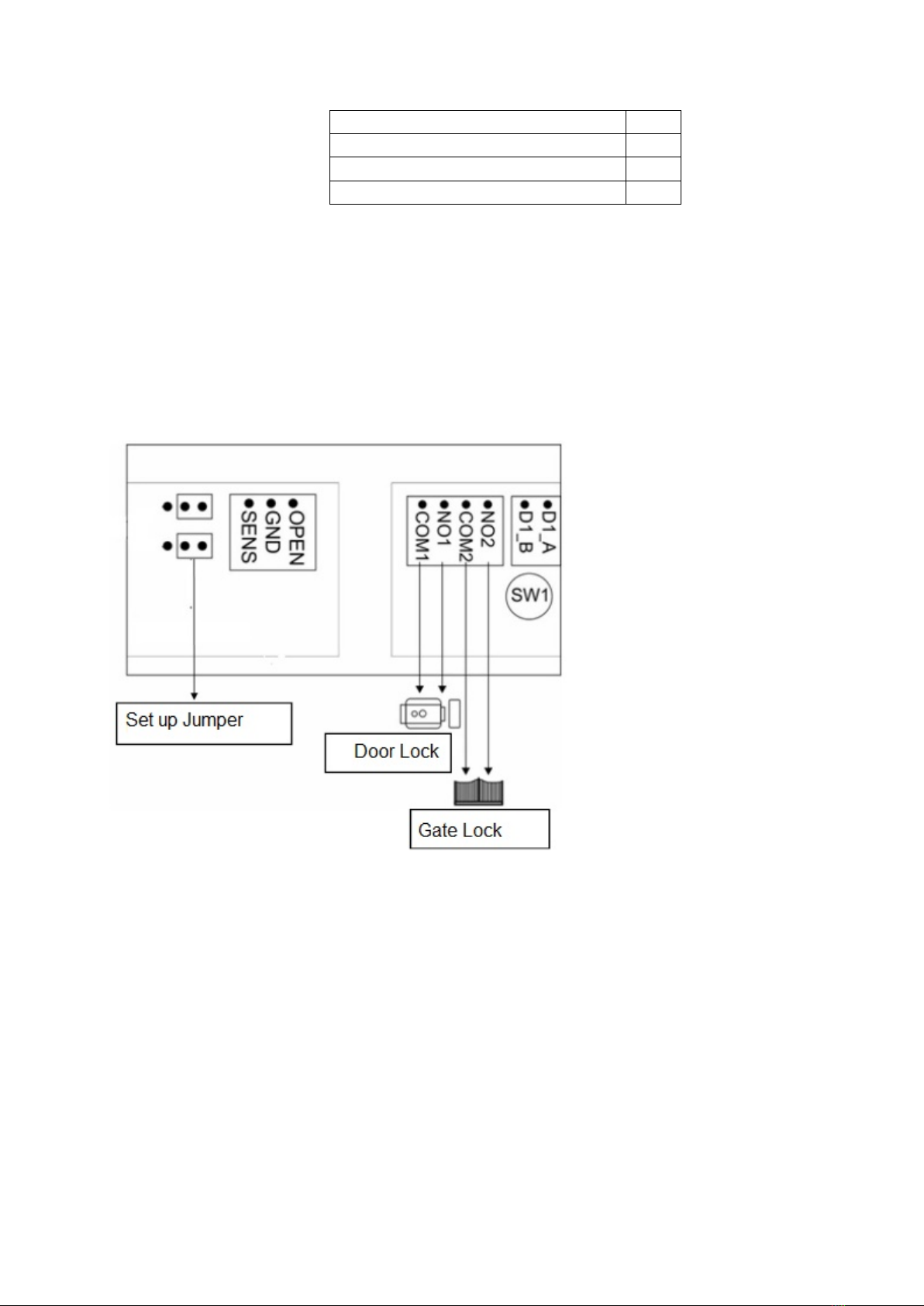
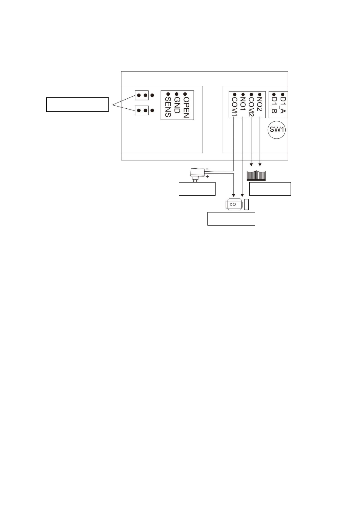
(1)Lock control jumper: Set the power mode for the door lock.
(2)Password reset button: Press and hold the reset button and restart the door station.
The password is successfully reset after two beeps.
(3)Multi-user connector
(4)Connector for external door control
OPEN: Connect the exit button.
SENS: Connect the door status detection switch.
Setting the door status detection function: In the main menu of the 2-wire internal monitor
in Settings"
select the option "Device configuration" , go to the "List of input stations" to mark the door
station, in the menu "Add to the list of monitoring devices" select "Edit" , enter the correct
password and enter the modification interface. Enable "Check door status" and set
"Magnetic Contact Type" to "Normally Open" or "Normally Closed" as needed. Set the time
in "Longest door opening time". If the door is open, the door station detects its condition
and if the door does not close by the set opening time of the door, the door stationwill trigger an
acoustic alarm.
(5)Lock connector: 5-1 is for door lock, 5-2 is for gate lock
(6)2-wire bus connector: Connect the 2-wire bus.
(7)SW1 DIP switch: To set up bus contacts. (Read the wiring diagram in the user guide)
3. Contents of the package

Door station
1pc
Hex wrench
1pc
Screws
4pc
Dowle
4pc
4. Wiring diagram
4.1 Electrical lock wiring diagram
4.11. Connection of the electric lock without additional power supply.
Note: At a distance of up to 5 m of the entrance station and the electric lock, it is not
necessary to use an additional power supply of the lock.
Fig.1
(1) Supported door locks:
A: NC (normally closed) lock,turn off to unlock. DC12V lock support 0.35 A (Max).
B: NO(normally open)lock, on unlocks. DC12V lock support ≤2 A (Instant).
(2) Jumper settings: As shown in Figure 1.
(3) Set the type and time of unlocking the lock:
In the main menu of the 2-wire internal monitor in "Settings", select the option "Device
configuration",
go to the "List of entry stations" to mark the door station, in the menu "Add to the list of
monitoring devices" select "Edit" , enter the correct password and enter the modification
interface.
Select the lock type and set the unlock parameters "Alarm Status" to "On" or "Off" and the
required time in the "Unlock Time" menu.

4.12. Connection of the electric lock with an additional source.
Fig.2
(1) Supported door locks: NO (normally open) lock, it is unlocked by switching on.
AC/DC5V-24V lock support, ≤ 3A (Instant).
(2) Jumper settings: As shown in Figure 2.
(3) Set the type and time of unlocking the lock:
In the main menu of the 2-wire internal monitor in "Settings", select the option "Device
configuration",
go to the "List of entry stations" to mark the door station, in the menu "Add to the list of
monitoring
device" select "Edit" , enter the correct password and enter the modification interface.
Select the lock type and set the unlock parameters "Alarm Status" to "On" or "Off" and the
required time in the "Unlock Time" menu.
Set up Jumpers
Power
Gate Lock
Door Lock

4.2 2-wire bus andodz ozi button
(1) Outgoing button:Press the exit button to unlock the door or gate. To select a door or gate
lock, go to the "Entry stations list" section of the
2-wire internal monitor to "Outgoing button type".
(2) The 2-wire bus does not have polarity.
(3) 2-wire bus contact settings: You must have the 2-wire bus contacts set up correctly. The
last monitor on the 2-wire bus should have the SW1 switch set to ON, see Figure 1.
Other monitors shouldalso have the SW 1 switch set to OFF, see Figure 2.
Note: The SW1 switch is on on by default.
Figure (1) Figure (2)
SW1 ON SW1 OFF

4.3 Wiring diagram
4.31 Single-pressure input station wiring diagram
(A) 1 monitor and 1 entry station
(A-1) DC 24V ,1A Adapter Power Supply
(A-2) Power supply to DIN rail DC24V, 1A

(B) 2 monitors and 1 entry station
(B-1) DC 24V ,1A Adapter Power Supply
(B-2) Power supply to DIN rail DC24V, 1A

(C) 5 monitors and 1 input station (maximum 5 monitors possible, see Figure 1)
(D) 4monitors and 2 entry stations (see Figure 2)
Figure 1 Figure 2
Note: For the specified wiring B and C, the ROOM ADDRESS on all monitors must be set to
the same value. When you press the button at the entrance station, all monitors will ring.

4.32. Diagram of connection of the 2-button entry station
Theinsideofthemonitor is set to the room address.
(A) DC 24V ,1A Adapter Power Supply
(B) Power supply to DIN rail DC24V, 1A
Note:
(1) 2-wire bus contact settings: The last monitor on the 2-wire bus should have the SW1
switch set to ON. Other monitors should have the SW 1 switch set to OFF.
(2) The length of the bus is indicated by L
(3) The same bus should use the same conductor with the same specification.
(4) The maximum length of the bus can be found in the chapter "Wire length".
(5) The bus does not have polarity.
(6) The address of the required internal monitor must be set as the destination of the call on
each button.

In the main menu of the 2-wire internal monitor in "Settings", select the option "Device
configuration", go
on the "List of entry stations" mark the door station, in the menu "Add to the list of
monitoring devices"
select "Edit" , enter the correct password and enter the modification interface. Go to
"Button Address" to set the call destination for each button.
5. User Manual
5.1 Warning
(5.11) Selecting the appropriate installation position to avoid direct sunlight and rain.
(5.12) Proposed installation height: 1.5 ~ 1.6 meters
(5.13) Before completing the installation, make sure that the power supply is not connected
5.2 Wire length
Themost large length of wires is limited by the use of different cables.
Cable length.
1. Cables maybe unenled.
2.Distance L2 means the distance from the entrance station to the power supply of the
system.
3.Distance L1 means the total distance of the 2-wire bus.
4.The same bus should use the same conductor with the same specification.
1Installation may be carried out by a person who is knowledgeable and properly trained
for VERIA systems.
NOTE: For security reasons, do not connect the videophone monitor to the power grid
before installation is complete. When installing the entrance station in a place with insufficient
protection for those children,toextend the life of thedevice, we strongly recommend filling the

space between the surface and the fixing bracket with silicone sealant outside the bottom for
condensate drainage.
Videophone wires should not be routed in the same cable as conductors of other
installations (bell, alarm, telecommunication systems) or in parallel more than 15 m with
another electrical system. Leadership.
WARNING: Failure to follow this procedure for installing the entry station may result in
permanent damage and loss of warranty!
DC24V/1A
Power
Adapter
Source
PW03A
Cable type
Monitor
length
vst.unit L1m
(MAX)
Power cable
length L2m
(MAX)
Monitor
length
vst.unit L1m
(MAX)
Power cable
length L2m
(MAX)
1
Parallel cable
125
125
125
125
2
Parallel cable
125
125
125
125
3
Twisted cable
150
150
150
150
4
Twisted cable
150
150
150
150
5
Cat-5 Standard
150
100
150
100
6
PAIR CABLE CAT-5
200
150
200
150
7
Telephone cable line
2x0,2mm
50
50
50
50
8
Parallel cable
100
100
100
100

5.3 Assembly
(1) Drill 4 holes according to location and insert dowels into the hole.
(2) Remove the front panel, insert the label and screw the front panel back on.
(3) Fix the mounting box with 4 screws.
(4) Connect the cable according to the system connection diagram.
(5) Fix the entrance station to the assembly box using the included hex cage
(1) Make a hole in the wall according to the size of the mounting box and insert dowels into
the hole.
(Note: 2 fixing screws are already installed in the screw holes before, see c. (7) on page 1.).
6. Technical specification
№
Info
Content
1
Communication
2 wires
2
Number of participants
1 participant / 2 participants
3
Audio
Two-way digital audio transmission
4
Video
1-channel digital video output
5
Camera
1 MPx HD Color CMOS Camera
6
Night light
Infrared diodes
7
Effective distance (0
Lux)
0.5 meters
8
Angle of view
110°(horizontal), 60°(vertical)
9
Buttons
1 / 2 mechanical buttons
10
Power
DC 24V
11
Supported electric
Locks
(1) Door lock without additional source:
NC lock DC12V 0.35A (Max) or
NO lock DC12V ≤2A (instantaneous).
(2) Door lock with additional source:
AC/DC5V-24V lock, current <3A.
12
Supported gateway
lock
One unlock signal (potential-free contact),
the current is less than 0.35A.
13
Lock control
Switched contact
14
Electricity consumption
Energy
3W (without lock power consumption)
15
Working temperature
-25°C to +60°C
16
Storage temperature
-30°C to +60°C

Warranty
SAFE HOME europe s.r.o. as a supplier, liable to the original buyer that this product will be
free from any defects in material and design during normal use and operation for a period of
24months from the date of sale. The supplier's obligation under this guarantee is limited to
the replacement of the product. Repair of the product or its replacement with a repaired
product is at the supplier's decision. The full terms and conditions and information regarding
warranty and warranty service can be found on the www.safe-home.eu.
SAFE HOME europe s.r.o. declares that the product complies with the basic requirementsand
other other decentprovisions of theDirective. The devicecan befreely operated in theEU.
Declarationsofconformity can befound on the website www.safe-home.eu.

VERIA
SAFE HOME europe, s.r.o. Seat of the company:
is a trademark for the company's products:
Havlíčkova 1113/47, 750 02 Přerov
Czech Republic
Tel.: +420 581 222 262
Website: www.veria.eu
SAFE HOME europe, s.r.o. reserves the right to modify
and change product specifications without notice.
All materials are carefully inspected, but the company
SAFE HOME europe, s.r.o. is not responsible for any
consequences caused by printing errors
or errors in the translations of this manual.
© 2021 SAFE HOME europe, s.r.o.
All rights reserved.
Table of contents
Other Veria Telephone manuals