VeriFone UX115 User manual

Verifone Part Number DOC159-013-EN-A, Revision A
UX115
Installation Guide

All rights reserved. No part of the contents of this document may be reproduced or transmitted in any form without the written
permission of Verifone, Inc.
The information contained in this document is subject to change without notice. Although Verifone has attempted to ensure the
accuracy of the contents of this document, this document may include errors or omissions. The examples and sample programs are
for illustration only and may not be suited for your purpose. You should verify the applicability of any example or sample program
before placing the software into productive use. This document, including without limitation the examples and software programs, is
supplied “As-Is.”
Verifone, Inc.
1-800-Verifone
www.verifone.com
Verifone Part Number DOC159-013-EN-A, Revision A
UX115 Installation Guide
© 2022 Verifone, Inc.
Verifone and the Verifone logo are registered trademarks of Verifone. Other brand names or trademarks associated with Verifone’s
products and services are trademarks of Verifone, Inc.
All other brand names and trademarks appearing in this manual are the property of their respective holders.
Comments? Please e-mail all comments on this document to your local Verifone Support Team.

UX115 INSTALLATION GUIDE 3
CONTENTS
PREFACE . . . . . . . . . . . . . . . . . . . . . . . . . . . . . . . . . . . . . . . 5
Audience. . . . . . . . . . . . . . . . . . . . . . . . . . . . . . . . . . . . . . . . . . . . . . . . . . . . . . . . 5
Organization . . . . . . . . . . . . . . . . . . . . . . . . . . . . . . . . . . . . . . . . . . . . . . . . . . . . . 5
Related Documentation . . . . . . . . . . . . . . . . . . . . . . . . . . . . . . . . . . . . . . . . . . . . 5
Conventions and Acronyms . . . . . . . . . . . . . . . . . . . . . . . . . . . . . . . . . . . . . . . . . 6
Document Conventions. . . . . . . . . . . . . . . . . . . . . . . . . . . . . . . . . . . . . . . . . . 6
Acronym Definitions . . . . . . . . . . . . . . . . . . . . . . . . . . . . . . . . . . . . . . . . . . . . 6
CHAPTER 1
Device Overview Features and Benefits . . . . . . . . . . . . . . . . . . . . . . . . . . . . . . . . . . . . . . . . . . . . . 7
Ease of Use . . . . . . . . . . . . . . . . . . . . . . . . . . . . . . . . . . . . . . . . . . . . . . . . . . 7
CHAPTER 2
Setup Selecting Unit Location. . . . . . . . . . . . . . . . . . . . . . . . . . . . . . . . . . . . . . . . . . . . . 8
Environmental Factors . . . . . . . . . . . . . . . . . . . . . . . . . . . . . . . . . . . . . . . . . . 8
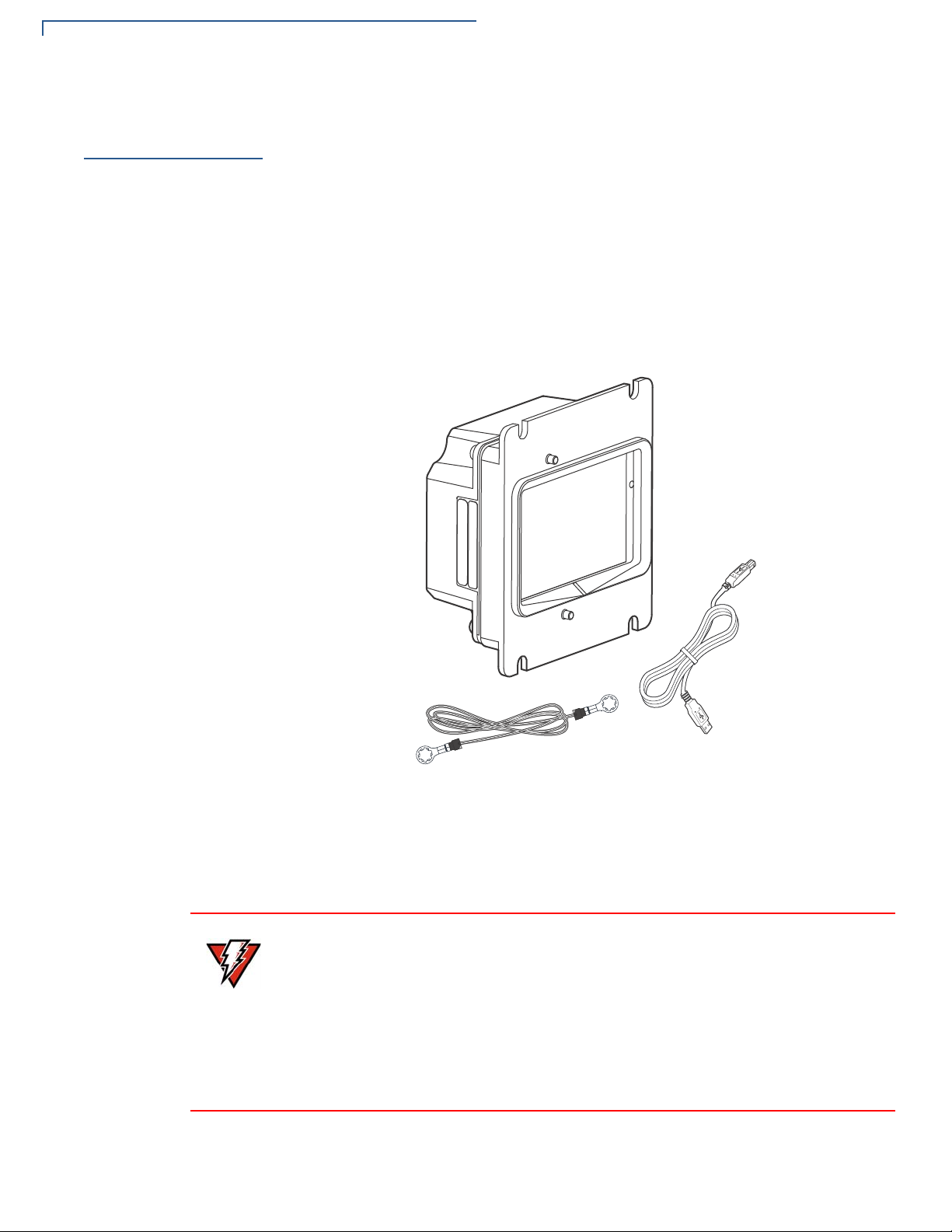
Unpacking the Shipping Carton . . . . . . . . . . . . . . . . . . . . . . . . . . . . . . . . . . . . . . 9
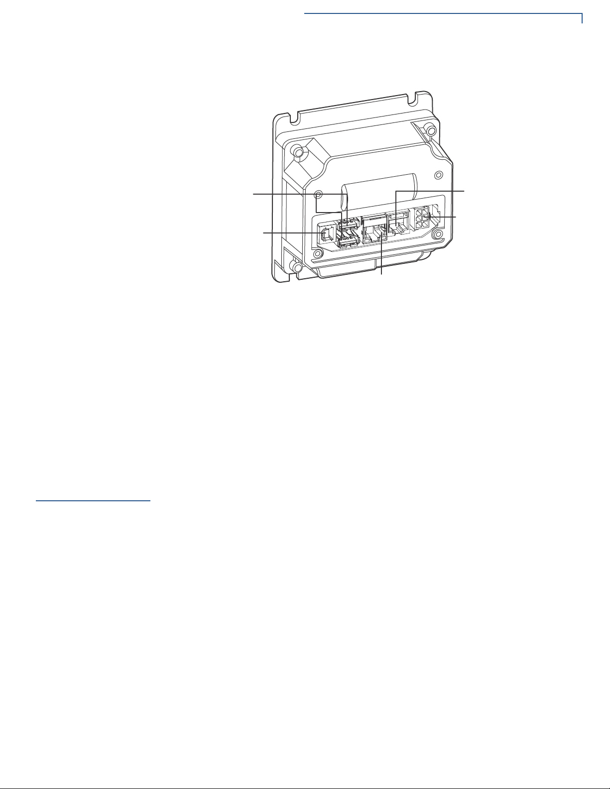
UX115 Connections Ports. . . . . . . . . . . . . . . . . . . . . . . . . . . . . . . . . . . . . . . 10
Mounting the UX115. . . . . . . . . . . . . . . . . . . . . . . . . . . . . . . . . . . . . . . . . . . . . . 10
Connecting UX115 to a Controlling Device . . . . . . . . . . . . . . . . . . . . . . . . . . . . 11
To connect to a controlling device through a USB . . . . . . . . . . . . . . . . . . . . 11
To connect to a controlling device through LAN . . . . . . . . . . . . . . . . . . . . . . 12
Connecting Power Supply . . . . . . . . . . . . . . . . . . . . . . . . . . . . . . . . . . . . . . . . . 13
Power Connection. . . . . . . . . . . . . . . . . . . . . . . . . . . . . . . . . . . . . . . . . . . . . 13
Grounding UX115 Device. . . . . . . . . . . . . . . . . . . . . . . . . . . . . . . . . . . . . . . . . . 14
CHAPTER 3
Specifications Unit Power Requirements . . . . . . . . . . . . . . . . . . . . . . . . . . . . . . . . . . . . . . . 16
Temperature . . . . . . . . . . . . . . . . . . . . . . . . . . . . . . . . . . . . . . . . . . . . . . . . . 16
External Dimensions . . . . . . . . . . . . . . . . . . . . . . . . . . . . . . . . . . . . . . . . . . . 16
Unit Weight . . . . . . . . . . . . . . . . . . . . . . . . . . . . . . . . . . . . . . . . . . . . . . . . . . 16
Peripheral Ports . . . . . . . . . . . . . . . . . . . . . . . . . . . . . . . . . . . . . . . . . . . . . . 16
Battery. . . . . . . . . . . . . . . . . . . . . . . . . . . . . . . . . . . . . . . . . . . . . . . . . . . . . . 16
CHAPTER 4
Maintenance and
Cleaning
Maintenance and Cleaning . . . . . . . . . . . . . . . . . . . . . . . . . . . . . . . . . . . . . . 17
CHAPTER 5
Service and Support Service Returns . . . . . . . . . . . . . . . . . . . . . . . . . . . . . . . . . . . . . . . . . . . . . . . . . 18
Accessories and Documentation . . . . . . . . . . . . . . . . . . . . . . . . . . . . . . . . . . . . 19
Connecting Cables . . . . . . . . . . . . . . . . . . . . . . . . . . . . . . . . . . . . . . . . . . . . 19
Power Cables . . . . . . . . . . . . . . . . . . . . . . . . . . . . . . . . . . . . . . . . . . . . . . . . 20
Documentation . . . . . . . . . . . . . . . . . . . . . . . . . . . . . . . . . . . . . . . . . . . . . . . 20

CONTENTS
4UX115 INSTALLATION GUIDE
CHAPTER 6
Troubleshooting
Guidelines
Blank Display . . . . . . . . . . . . . . . . . . . . . . . . . . . . . . . . . . . . . . . . . . . . . . . . . . . 21
APPENDIX 7
Port Pinouts UX115 Ports . . . . . . . . . . . . . . . . . . . . . . . . . . . . . . . . . . . . . . . . . . . . . . . . . . . . 22
Power Port (DC-in) . . . . . . . . . . . . . . . . . . . . . . . . . . . . . . . . . . . . . . . . . . . . 22
RS-232 Port (COM1) . . . . . . . . . . . . . . . . . . . . . . . . . . . . . . . . . . . . . . . . . . 22
Ethernet Port (LAN) . . . . . . . . . . . . . . . . . . . . . . . . . . . . . . . . . . . . . . . . . . . 23
USB Pinout (Host Port) . . . . . . . . . . . . . . . . . . . . . . . . . . . . . . . . . . . . . . . . . 23
USB Pinout (Client Port) . . . . . . . . . . . . . . . . . . . . . . . . . . . . . . . . . . . . . . . . 23

UX115 INSTALLATION GUIDE 5
PREFACE
This guide is the primary source of information for setting up and installing
the UX115 device.
Audience
This guide describes the unit’s features and provides the basic information for its
installation and configuration.
Organization
This guide is organized as follows:
Chapter 1, Device Overview. Provides an overview of the UX115 device.
Chapter 2, Setup. Explains the setup and installation of the device, selecting a
location, and establishing connections with other devices.
Chapter 3, Specifications. Discusses the power requirements and dimensions of
the device.
Chapter 4, Maintenance and Cleaning. Explains the maintenance of the device.
Chapter 5, Service and Support. Provides information on contacting your Verifone
service provider and information on how to order accessories or documentation
from Verifone.
Chapter 6, Troubleshooting Guidelines. Provides troubleshooting guidelines
should you encounter a problem with unit installation and configuration.
Appendix 7, Port Pinouts. Shows the different pinout specifications for
the UX115 device.
Related
Documentation
To learn more about the UX115 device, refer to the following set of documents and
their associated Verifone Part Numbers (VPNs).
UX115 Certifications and Regulations Sheet VPN DOC159-011-EN
UX115 Quick Installation Guide VPN DOC159-012-EN

PREFACE
Conventions and Acronyms
6UX115 INSTALLATION GUIDE
Conventions and
Acronyms
This section describes the conventions and acronyms used in this guide.
Document
Conventions
Various conventions are used to help you quickly identify special formatting.
Table 1 describes these conventions and provides examples of their use.
Acronym Definitions
Various acronyms are used in place of the full definition. Table 2 presents
acronyms and their definitions.
Table 1 Document Conventions
Convention Meaning Example
Blue Text in blue indicates terms that
are cross referenced.
See Conventions and
Acronyms.
The pencil icon is used to
highlight important information.
If exchanging cables use a
Verifone-approved cable.
The caution symbol indicates
possible hardware or software
failure, or loss of data.
Avoid placing metallic objects at
the front of the card reader
The lightning symbol is used as
a warning when bodily injury
might occur.
For safety, do not string cables
or cords across a walkway.
NOTE
CAUTION
WARNING
Table 2 Acronym Definitions
Acronym Definitions
MRA Merchandise Return Authorization
VPN Verifone Part Number
RF Radio Frequency
RJ45 Registered Jack 45 modular connector
COM Communications port
LAN Local Area Networks
RS-232 Recommended Standard 232
OTG On-The-Go
USB Universal Serial Bus

UX115 INSTALLATION GUIDE 7
CHAPTER 1
Device Overview
This chapter provides a brief description of Verifone’s UX115 devices.
The UX115 Auxiliary display is a UX family device used in various unattended
scenarios including drive-through, vending, ticketing, parking and petrol station.
Features and
Benefits
It can be operated as a companion device to display information from a payment
device and can be connected by USB or Ethernet.
The UX115 can display static images such as line items from an order, the total
amount of an order, QR codes, pictures or video clips.
Ease of Use
The following features of the device simplify transactions in various environments:
•Designed for indoor and outdoor use.
•Various connectivity options integrated into the device to conveniently suit
most unattended environments.
•Connects with UX300, UX301, UX410 and Verifone unattended POS
terminals.
•UX115 design supports payment transactions in a variety of payment
situations, such as transportation, vending, and kiosk environments.

UX115 INSTALLATION GUIDE 8
CHAPTER 2
Setup
This chapter describes the setup procedure for the UX115 in the following
sections:
•Selecting Unit Location
•Unpacking the Shipping Carton
•Mounting the UX115
•Connecting UX115 to a Controlling Device
•Connecting Power Supply
•Grounding UX115 Device
Selecting Unit
Location
Use the following guidelines when selecting a location for the UX115 device:
•Select a location convenient for the customer.
•Avoid dusty, hot or damp locations.
Environmental
Factors
The UX115 is sealed to IP65 rating when mounted correctly in an enclosure.
WARNING
Pour la sécurité, ne sont pas des câbles à cordes ou des cordons de votre
armoire d'installation ou de logement à travers une passerelle.
For safety, do not string cables or cords from your installation cabinet or housing
across a walkway.

SETUP
Unpacking the Shipping Carton
9UX115 INSTALLATION GUIDE
Unpacking the
Shipping Carton
Open the shipping carton and carefully inspect its contents for possible tampering
or shipping damage.
To unpack the
shipping carton 1Validate the authenticity of the sender by verifying the shipping tracking
number and other information located on the product order paperwork.
2Remove the items from the shipping carton. The standard package contains:
•The UX115 unit
•Grounding strap
•USB cable
Figure 1 UX115 Device
3Remove any protective wrap before mounting the unit.
4Save the shipping carton and packing material for future repacking or moving
of the device.
WARNING
Ne pas utiliser un appareil qui a été endommagé.
Si une étiquette ou d'un composant semble endommagé, se il vous plaît aviser la
compagnie de navigation et votre fournisseur de services Verifone
immédiatement.
Do not use a unit that has been damaged.
If a label or component appears damaged, please notify the shipping company
and your Verifone service provider immediately.

SETUP
Mounting the UX115
UX115 INSTALLATION GUIDE 10
UX115 Connections
Ports
The UX115 features the following ports:
Figure 2 UX115 Connection Ports
•USB device (Type B) [client]
•2x Powered USB (Type A) Ports
•1 x Full Speed, High Powered USB (Type A), Port 1 [Host]
•1 x Powered USB (Type A), Port 2 [OTG]
•Power port 12V DC to 24V DC
•LAN
•COM1 (RS-232)
Mounting the
UX115
This section shows how to attach the UX115 device to the installation panel for
stability and security.
USB Client
port
USB Host
ports
LAN port
Power
Port
RS-232
port

SETUP
Connecting UX115 to a Controlling Device
11 UX115 INSTALLATION GUIDE
Use the following steps to install the UX115 device:
Figure 3 Mounting the UX115 device
1Align the UX115 device mounting holes to the installation panel holes.
2Insert four bolts and tighten the nuts using a recommended tightening torque
of 5.0 kgf cm (0.49 Nm or 4.3 lbf in).
Connecting
UX115 to a
Controlling
Device
The UX115 device can be controlled directly using USB or indirectly using
Ethernet.
This section discusses how to connect the UX115 device to a controlling device.
To connect to a
controlling device
through a USB
1Connect the USB Type B plug to the rear connector of the UX115 device.
NOTE
The UX300 host device installs the USB device driver automatically. The USB
data is encrypted with authentication upon startup.

SETUP
Connecting UX115 to a Controlling Device
UX115 INSTALLATION GUIDE 12
2Connect the other end of the cable to a USB port on the controlling device.
Figure 4 Sample connection to a UX300 Controller through USB
To connect to a
controlling device
through LAN
1Connect the LAN port plug to the rear connector of the UX115 device and the
other end to the network.
2Connect the other end of the cable to a LAN port on the controlling device and
the other end to the network.
Figure 5 Sample connection to a UX300 Controller through LAN

SETUP
Connecting Power Supply
13 UX115 INSTALLATION GUIDE
Connecting
Power Supply
Verifone can provide a power supply for the UX115 device if required.
For more details on the usage of the power supply, contact Verifone
representative.See Accessories and Documentation.
Attach and route all cables between the UX115 device and all peripheral units
before connecting to the power source.
Power Connection
The UX115 device connects to external power using a power pack (PWR159-00X-
01-A).
Connect the power cable to the power port on the UX115 device and the other end
to your power source.
Figure 6 Connecting Power Supply to the UX115
CAUTION
L'utilisation d'une alimentation mal classé peut endommager l'appareil ou
provoquer un dysfonctionnement.
Verifone recommande la PWR159-00X-01-A.
Voir les caractéristiques de l'information d'alimentation.
Using an incorrectly rated power supply can damage the unit or cause it to
malfunction.
Verifone recommends the PWR159-00X-01-A power packs.
See Specifications for power supply information.
NOTE
To protect against possible damage caused by lightning strikes and electrical
surges, Verifone recommends installing a power surge protector.

SETUP
Grounding UX115 Device
UX115 INSTALLATION GUIDE 14
For more details on the usage of the power supply, contact Verifone
representative. For cable ordering information, see Accessories and
Documentation.
Grounding
UX115 Device
When the UX115 device is connected to the UX300/UX301/UX410 controller, it is
important to ground the units.
1Remove a mounting nut, exposing a stud from the back of the UX115 device
(do not remove the cable retainer nut). Figure 7 See (A).
2Attach the grounding cable (VPN WIR159-302-01-A) from the UX115 Device
to the UX300 and the grounding cable (VPN WIR159-302-02-A) from the
UX115 device to a ground installation. Figure 7 See (B).
Figure 7 Grounding UX115 device and UX300 Units
3Tighten the nut to secure the UX115 device.
4Remove a mounting nut, exposing a stud from the back of the UX300 unit.
NOTE
For cable ordering information, see Accessories and Documentation.
-%4%2#!",%
-%4%2
#!",%
-%4%2
#!",%
A
B
C
C
NOTE
Tighten the nuts with a recommended torque of 5.0 kgf cm (0.49 Nm or 4.3 lbf in).

SETUP
Grounding UX115 Device
15 UX115 INSTALLATION GUIDE
5On the UX300 unit stud, attach the other end of the grounding cable (VPN
WIR159-302-01-A) from the UX115 and the second grounding cable (VPN
WIR159-302-02-A, provided as a UX300 accessory) to a ground installation.
Figure 7 See (B).
6Tighten the nut to secure the UX300 device.
7Connect the other end of both ground cables to the nearest ground
installations, to complete the grounding of the UX115 and UX300. Figure 7
See (C).
NOTE
Tighten the nuts with a recommended torque of 5.0 kgfcm (0.49 Nm or 4.3 lbf in).

UX115 INSTALLATION GUIDE 16
CHAPTER 3
Specifications
This chapter discusses power requirements, dimensions, and other specifications
of the UX115 device.
Unit Power
Requirements
•Operating Voltage: 12 to 24V DC
Temperature
•Operating Temperature: -30°C to 70°C (-22°F to 158°F)
•Storage Temperature: -35°C to 70°C (-31°F to 158°F)
•Relative Humidity: 10% to 90% RH non-condensing IK09, IP65
External
Dimensions
•Length: 51.6 mm (2.03 in)
•Width: 104 mm (4.09 in)
•Height: 112.2 mm (4.42 in)
Unit Weight
•512g (18.06 oz)
Peripheral Ports
•USB Device (Type B) [client]
•2x Powered USB (Type A) Ports
•1 x Full Speed, High Powered USB (Type A), Port 1 [Host]
•1 x Powered USB (Type A), Port 2 [OTG]
•Power port 12V DC to 24V DC
•LAN
Battery
•Minimum 5 years

UX115 INSTALLATION GUIDE 17
CHAPTER 4
Maintenance and Cleaning
Maintenance and
Cleaning
Your UX115 device is a product of superior design and craftsmanship and should
be treated with care. It has no user-serviceable parts.
The following suggestions will help you protect your warranty coverage.
•Do not store the device in hot areas. High temperatures can shorten the
life of electronic devices, damage batteries, and warp or melt certain
plastics.
•Do not store the device in cold areas. When the device returns to its
normal temperature, moisture can form inside the device and damage
electronic circuit boards.
•Do not drop, knock, or shake the device. Rough handling can break
internal circuit boards and fine mechanics.
•Do not use harsh chemicals, cleaning solvents, or strong detergents to
clean the device. Use a wet soapy cloth to clean the device surfaces.
The following table lists the chemicals that you can use for cleaning. Chemicals
that are not safe to use are also listed. Never use these chemicals as they can
deteriorate plastic or rubber parts.
These suggestions apply equally to its attachments or accessories. If your device
is not working properly, take it to the nearest Verifone-authorized service provider
for servicing or replacement.
Table 3Chemicals for Cleaning
Recommended n-hexane, gasoline, ethyl-alcohol
Not Recommended acetone, butanone, thinner, trichloroethylene, or ketone-based
solvents

UX115 INSTALLATION GUIDE 18
CHAPTER 5
Service and Support
For UX115 problems, contact your local Verifone representative or service
provider.
For device product service and repair information:
•USA – Verifone Service and Support Group, 1-800-834-4366,
Monday - Friday, 8 A.M. - 8 P.M., eastern time.
•International – Contact your Verifone representative.
Service Returns
Before returning the UX115 device to Verifone, you must obtain a Merchandise
Return Authorization (MRA) number. The following procedure describes how to
return one or more UX115 device for repair or replacement (U.S.A customers
only).
1Gather the following information from the printed labels (see Figure 8) on the
side of each unit to be returned:
•Product ID, including the model and part number. For example,
“M159-410-xxx-WWB” and “PTID xxxxxxxx.”
•Serial number (S/N xxx-xxx-xxx).
2Within the United States, call Verifone toll-free at 1-800-834-4366.
3Select the MRA option from the automated message. The MRA department is
open Monday to Friday, 8 A.M.–8 P.M., eastern time.
4Give the MRA representative the information gathered in Step 1.
If the list of serial numbers is long, you can fax the list, along with the
information gathered in Step 1, to the MRA department at 1-727-953-4172
(U.S.A).
•Please address the fax clearly to the attention of the “Verifone MRA Dept.”
•Include a telephone number where you can be reached and your fax
number.
NOTE
International customers, please contact your local Verifone representative for
assistance with your service, return, or replacement.

SERVICE AND SUPPORT
Accessories and Documentation
19 UX115 INSTALLATION GUIDE
•You will be issued MRA number(s) and the fax will be returned to you.
5Describe the problem(s) and provide the shipping address where the repaired
or replacement unit must be returned.
6Keep a record of the following items:
•Assigned MRA number(s).
•Verifone serial number assigned to the unit you are returning for service or
repair (serial numbers are located on the side of the unit, see Figure 8).
•Shipping documentation, such as air bill numbers used to trace the
shipment.
•Model(s) returned (model numbers are located on the Verifone label on the
side of the Controller unit).
Figure 8 Information Label on Left Side of UX115
Accessories and
Documentation
Verifone produces accessories and documentation for the contactless reader.
When ordering, please refer to the part number in the left column.
Verifone Online Store at www.store.verifone.com
•USA – Verifone Customer Development Center, 1-800-834-4366,
Monday - Friday, 7 A.M. - 8 P.M., eastern time.
•International – Contact your Verifone representative.
Connecting Cables
Use the following cables to connect the antenna unit to the controller unit. Contact
your local Verifone distributor to determine which cable fits your needs:
NOTE One MRA number must be issued for each unit you return to Verifone, even if
you are returning several of the same models.
MODEL AND
SERIAL NUMBERS
CBL000-045-01-B USB Type A to B cable, 1 m long
CBL000-045-02-B USB Type A to B cable, 0.3 m long
CBL000-083-03-A Ethernet Cable, 3 m long
CBL000-016-01-A RJ45 to RS232

SERVICE AND SUPPORT
Accessories and Documentation
UX115 INSTALLATION GUIDE 20
Power Cables
Use the following power cables for connecting power to the controller unit.
Contact your local Verifone representative or service provider to identify the best
cable for your needs.
Documentation
CBL501-001-01-A UX Y Cable
CBL501-002-01-A Wire end cable (4pin)
MET159-159-01-A UX115 ARS Development plate
PWR159-002-01-B 12 V, 3.3 A power supply unit (PSU) Efficiency L6
CBL000-081-01-A EU power cord for PWR159-002-01-A PSU
CBL000-080-01-A US power cord for PWR159-002-01-A PSU
CBL000-078-01-A
(1.8m)
CBL000-034-02-A
(0.6m)
UK power cord for PWR159-002-01-A PSU
VPN DOC159-011-EN UX115 Certifications and Regulations Sheet
VPN DOC159-012-EN UX115 Quick Installation Guide
Table of contents
Other VeriFone Card Reader manuals
Popular Card Reader manuals by other brands

Pepperl+Fuchs
Pepperl+Fuchs ODT-MAH120-HD quick start guide

Rosslare
Rosslare AY-U910 Installation and user manual

Shintaro
Shintaro SH-XCRUSB3 quick start guide

Megavoice
Megavoice Envoy 2 S Series user guide

Decagon Devices
Decagon Devices ProCheck Operator's manual

Siemens
Siemens PR500-Cotag installation guide