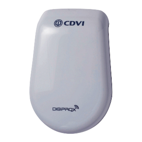
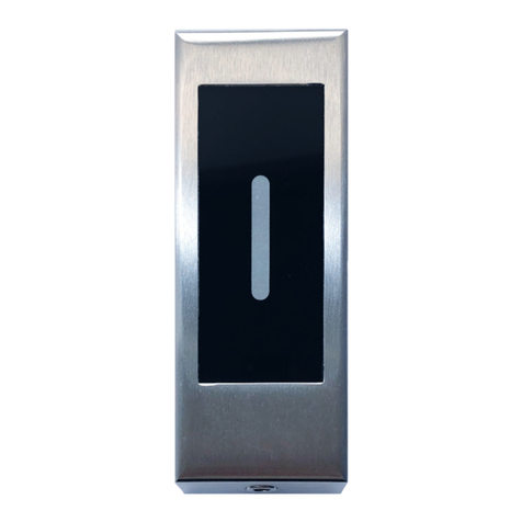
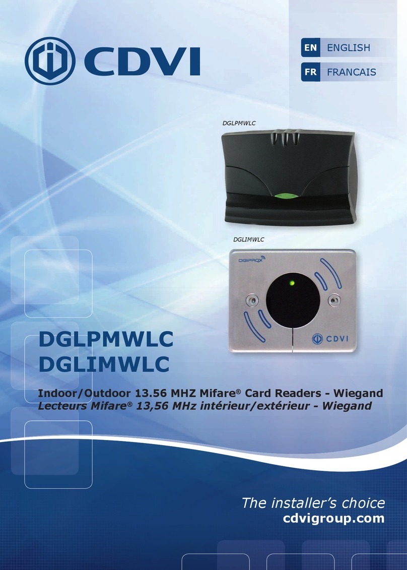
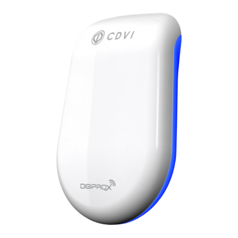
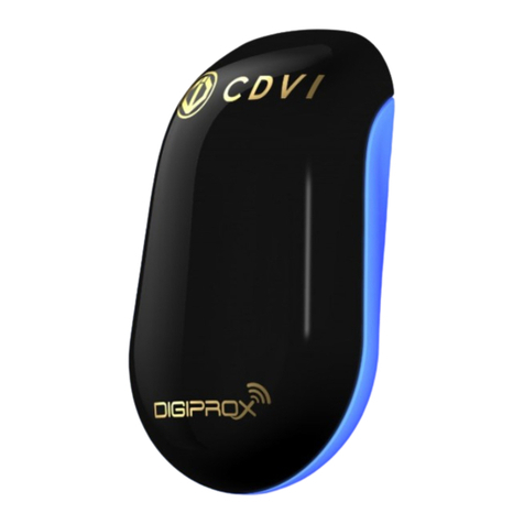
CDVI STAR1M User manual

cdvigroup.com 1
Le choix de l’installateur
cdvigroup.com
Français
English
FR
EN
STAR1M
Centrale autonome/Lecteur Mifare® 13,56MHz
Mullion Mifare®card reader.

cdvigroup.com
2
MANUEL D’INSTALLATION FR
STAR1M - Centrale autonome / Lecteur Mifare®
1] PRÉSENTATION DU PRODUIT
- Produit 2 en 1 :
fonctionnement centrale autonome
fonctionnement lecteur Mifare®(13,56 MHz)
- Électronique résinée
- Signalisation lumineuse et sonore
- 3m de câble (10 brins - AWG28)
- Disponible en noir
- Capacité : 150 badges (mode miroir)
300 badges (mode standard)
Dimensions (L x l x P) : 130 x 41 x 28 mm
Technologie : 13,56 MHz
Protocole : Mifare®classic, Ultralight C
Alimentation : 12V DC
Consommation : 120 mA
Wiegand 26/30/44 bits (lecteur Mifare®)
2] RAPPELS ET RECOMMANDATIONS STAR1M
Recommandations d’installation
Pour sécuriser l’installation, n’oubliez pas
de placer la varistance sur le système de
verrouillage en parallèle sur les bornes de
l’alimentation.
Câble préconisé
Câble 10 conducteurs (AWG28)
Alimentations préconisées
ADC335 et BS60 (lorsque le produit
n’est alimenté ni par la centrale, ni par le
contrôleur de porte [INTBUSW]).
L’alimentation utilisée doit être une
alimentation conçue pour être une source
de puissance limité selon EN 60950-1
Environnement
Si vous installez ce produit dans un
environnement marin/salin, il est
préconisé de passer du vernis en bombe
sur les contacts après câblage an de
prévenir le risque d’oxydation.
Ce produit est livré avec une
varistance.
Celle-ci doit être montée
directement
sur les bornes de la gâche (ventouse,
moteur,…) commandée par l’équipement. Si
l’appareil fonctionne avec plusieurs gâches,
chacune doit être équipée de varistance.
La varistance limite les surtensions
provoquées par
le bobinage de la gâche –
effet
de self. Dans le cas où la ventouse
utilisée est du type “Shear Lock”,
celle-ci
doit être alimentée par une alimentation
indé
pendante du STAR1M.
Joint
d’étanchéité Vis TF
3x30 Cheville
plastique S5 Embout
tournevis TORX®
Vis TORX®
3x8 Varistance Badge METALR
STAR1M 1 2 2 1 1 1 1
3] ÉLÉMENTS FOURNIS
Pour un
éclairage
optimal,
attention de ne
pas plier
le câble à
l’intérieur du
produit.
R
76,7
R
35,4
7
60
30
Ce document est la propritété exclusive de CDVI, il ne peut être communiqué à des tiers sans son autorisation.
This document is the exclusive property of CDVI and it may not be disclosed to others without permission.
31, av du Gal Leclerc
93691 PANTIN CEDEX
F R A N C E
Tel : 33(0)148910102
Fax
: 33(0)148912121
www.cdvi.com
Plan M1806-VdE
Edition 00
Date 01/10/2009
ECHELLE 1:1
A4V
DES.: A. Broustal
Matière : ...
Tolérance gale :
0.1
Etat de surface : Ra 3,2
A0228015
Badge PP New
plan coté pour dépôt "dessin&modèle"
C.A.: ...
Vol. (mm
3
)
:
Poids (g) :
IK09
IP54 -25°C à +70°C
Nous, CDVI, déclarons que le STAR1M est conforme à la directive 2014/53/UE.
La déclaration complète est téléchargeable sur le site www.cdvi.com.
Bande de fréquence : 13,553 - 13,567 MHz
Puissance maximale transmise : 42 dBμA/m
Merci pour l’achat de ce produit et pour la conance que vous accordez à notre entreprise
cdvigroup.com 3
MANUEL D’INSTALLATION FR
STAR1M - Centrale autonome / Lecteur Mifare®
4] FONCTIONNEMENT
Dipswitch Mode autonome
(page 4) Mode Wiegand
(page 9)
1OFF ON
2
OFF ON OFF ON
Changer
badge maître Fonctionnement
NORMAL Option du
Dipswitch 3 44 bits
3
OFF ON OFF ON
Mode miroir
(page 6) Mode standard
(page 7) 26 bits 30 bits
4Non assigné
Les différentes positions des Dipswitchs permettent de passer le STAR1M en Centrale
autonome ou en Lecteur Mifare®.
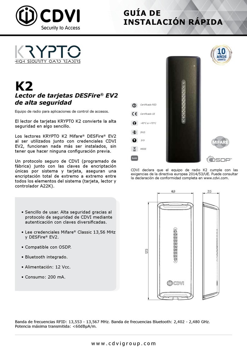
5] SCHÉMA DE CÂBLAGE
C56
C58
C61
1
MM10
4
3
2
1
ON
ON
ON
ON
L7
Q6
Q7
Q8
R77
R78
R79
P1
1P3
BZ3
C6
C24
C59
-
+
MM1
MM14
CR3
+
-
CR10
CR25
CR26
CR24
MM3
MM15
CR12
CR13
CR15
I1
+
-
+
-
MM16
CR22
P2
-
+
CR19
CR21
CR20
CR28
CR27
CR29
CR11
R70
R67
R68
R64
R69
R65
C68
CR30
STAR1M Raccordements
Mode autonome Mode Wiegand
Rouge 12V DC 12V DC
Noir 0 V 0 V
Vert / Data 0
Blanc / Data 1
Bleu Contact relais normalement
ouvert - NO /
Gris Commun - C /
Violet Contact relais normalement
fermé - NC /
Marron Bouton poussoir de sortie Entrée buzzer
Jaune /Entrée voyant vert
Orange /Entrée voyant rouge
Voyants au démarrage :
- Vert (1s)
- Rouge (1s)
- Bleu + BIP (1s)
Voyants en fonctionnement général :
- Repos : bleu
- Passage badge : vert ou rouge
Pour changer de mode, redémarrer le STAR1M

cdvigroup.com
4
MANUEL D’INSTALLATION FR
STAR1M - Centrale autonome / Lecteur Mifare®
6] PROGRAMMATION
Avant la mise sous tension, sélectionnez le mode de gestion (lecteur
Mifare® ou centrale autonome).
1] Lecteur Wiegand Mifare® (DIP1 sur ON) à connecter à
une centrale
- vert
- rouge
- bleu + buzzer (séquence de démarrage)
2] Centrale autonome (DIP1 sur OFF) = réglage usine
- vert
- rouge
- bleu + buzzer (séquence de démarrage)
- jaune/vert : attente présentation du badge maître (lors
de la 1ère mise sous tension)
1
ON
2
ON
3
ON
4
ON
ON ON ON ON
1234
ON
OFF
ON
OFF
- Conforme Mifare® - ISO 14443A (Mifare®classic).
- Programmation via le badge maître directement sur le lecteur :
- Le badge Maître et utilisateurs s’enregistrent directement sur le lecteur
- Capacité : 1 badge maître + 300 ou 150 badges utilisateurs (selon mode)
- Gestion 1 porte : 1 relais NO/NC (1A, 12V DC)
- Mode « liste blanche » : permettant de fonctionner qu’avec les badges pré-enregistrés.
- 1 entrée bouton poussoir
- Fonctionne avec les badges METAL, PVP (Mifare®), les cartes BV (ISO Mifare®
format carte de crédit), ERV et ERNV.
7] FONCTIONNEMENT DE LA CENTRALE AUTONOME
Raccordement d’un verrouillage à émission
(mode autonome)
12V DC
ADC335
Bouton poussoir
Gâche à émission

cdvigroup.com 5
MANUEL D’INSTALLATION FR
STAR1M - Centrale autonome / Lecteur Mifare®
Notre gamme de verrouillage intègre une varistance.
Raccordement d’un verrouillage à rupture (mode autonome)
12V DC
ADC335
Bouton poussoir
Ventouse
gâche à rupture
Fonctionnement normal :
1
ON
2
ON
3
ON
4
ON ON
OFF
Présenter le badge utilisateur.
Badge reconnu :
BIP + voyant vert + activation du relais
Badge non reconnu :
BIP + voyant rouge
Voyant bleu
Basculer DIP2 sur ON
En sortie d’usine, le lecteur est conguré en mode miroir.
Pour toute première mise en service, veuillez enregistrer un badge maître
(voir procédure page 8).

cdvigroup.com
6
MANUEL D’INSTALLATION FR
STAR1M - Centrale autonome / Lecteur Mifare®
Ajouter des badges utilisateurs (max. 150) :
Entrée
en programmation
Voyant jaune
Présenter le badge utilisateur.
BIP + voyant vert puis retour au jaune Voyant bleu
Présenter badge maître
Présenter le badge maître ou
attendre 10 secondes
Sortie de programmation
À répéter pour chaque badge à enregistrer
Présenter le badge miroir.
2 BIPs + un clignotement voyant vert
Effacer des badges utilisateurs :
Entrée en programmation
Voyant jaune
Présenter le badge utilisateur ou son shadow
BIP + voyant vert puis retour au jaune
Représenter le même badge une 2ème fois
BIP+voyant rouge puis retour au jaune
La paire de badge est effacée
Si badge connu, cela va enregistrer le badge.
Voyant bleu
Présenter badge maître
Présenter le badge maître ou
attendre 10 secondes
Sortie de programmation
7.1 Mode miroir
Le mode miroir consiste à enregistrer les badges par paires. Parmi la paire créée, il y aura
un badge utilisateur et son badge miroir. Ces 2 badges peuvent donner accès. Le badge
utilisateur est donné à l’utilisateur et le badge miroir est conservé par le gestionnaire de
site. En cas de perte ou de vol, pour supprimer le badge utilisateur, il suft de présenter le
badge utilisateur ou son badge miroir devant le lecteur pour effacer la paire
1
ON
2
ON
3
ON
4
ON ON
OFF
Position Dipswitch

cdvigroup.com 7
MANUEL D’INSTALLATION FR
STAR1M - Centrale autonome / Lecteur Mifare®
Ajouter des badges utilisateurs (max. 300) :
Entrée en programmation
Voyant jaune
Présenter le badge utilisateur.
BIP + voyant vert puis retour au jaune
à répéter pour chaque badge à enregistrer
Si badge déjà ajouté, voyant éteint + bip puis retour au jaune
Voyant bleu
Entrée en programmation
Voyant jaune
Présenter le badge utilisateur.
BIP + voyant éteint puis retour au jaune
Représenter le même badge une seconde fois
BIP + voyant rouge puis retour au jaune
Si badge inconnu, cela va enregistrer le badge
Voyant bleu
Effacer des badges utilisateurs :
Présenter badge maître
Présenter le badge maître ou
attendre 10 secondes
Sortie de programmation
Présenter badge maître
Présenter le badge maître ou
attendre 10 secondes
Sortie de programmation
Voyant bleu
7.2 Mode standard
1
ON
2
ON
3
ON
4
ON ON
OFF
Le mode standard consiste à créer des badges uniques. Chaque badge créé est donné à
l’utilisateur. Pour supprimer un badge utilisateur, il faut présenter le badge en question
devant le lecteur.
Position Dipswitch

cdvigroup.com
8
MANUEL D’INSTALLATION FR
STAR1M - Centrale autonome / Lecteur Mifare®
1
ON
2
ON
3
ON
4
ON ON
OFF
Rétablir
l’alimentation
Activation voyant blanc/rouge lors de
la durée d’effacement de la mémoire
Suivi de la séquence de démarrage
Effacer tous les badges utilisateurs :
Couper l’alimentation
Basculer le DIP1 sur ON
Couper
l’alimentation
1
ON
2
ON
3
ON
4
ON ON
OFF
Basculer le DIP1 et DIP2 sur OFF
Mode lecteur autonome activé
Rétablir l’alimentation
Pour tout effacer revenir en mode wiegand Rétablissement mode miroir (autonome)
7.3 Fonctions communes
Présenter la badge maître ou attendre
10 secondes
Clignotement voyant
rouge et blanc + BIP
1 clignotement : 1 seconde
Programmation du temps d’ouverture (porte, serrure..) :
Entrée en
programmation
Voyant jaune
Appuyer sur le bouton poussoir
Chaque pression : 1 seconde Voyant bleu
Créer ou remplacer un badge Maître :
1
ON
2
ON
3
ON
4
ON ON
OFF
Basculer DIP2 sur OFF
Voyant jaune
+ BIP
Présenter badge maître
BIP + voyant éteint
1
ON
2
ON
3
ON
4
ON ON
OFF
Basculer DIP2 sur ON
BIP
Voyant bleu
Présenter badge maître
Par défaut, le temps est de 5 secondes, congurable de 01 à 99 secondes.

cdvigroup.com 9
MANUEL D’INSTALLATION FR
STAR1M - Centrale autonome / Lecteur Mifare®
8.1 Format de sortie WIEGAND 26, 30 et 44 bits
8] FONCTIONNEMENT LECTEUR MIFARE®
OFF
1
ON
2
ON
3
ON
4
ON ON
OFF
1
ON
2
ON
3
ON
4
ON ON
OFF
1
ON
2
ON
3
ON
4
ON ON
Format Wiegand 30 bits
Format Wiegand 44 bits
Format Wiegand 26 bits
À savoir :
- Passage du « mode miroir » au « mode indépendant » : les badges sont conser-
vés mais deviennent indépendants.
- Passage du « mode independant » au « mode miroir » : l’intégralité des badges
est effacée

cdvigroup.com
10
MANUEL D’INSTALLATION FR
STAR1M - Centrale autonome / Lecteur Mifare®
PARAMÉTRAGE
VOYANT VERT
PARAMÉTRAGE
VOYANT ROUGE
VERT ACCÈS AUTORISÉ
ROUGE ACCÈS REFUSÉ
BLEU EN ATTENTE
ÉTAT
VOYANTS
8.3 Paramétrage des voyants sur le système CENTAUR
8.2 Paramétrage des voyants sur le système ATRIUM
PARAMÉTRAGE
VOYANT VERT
PARAMÉTRAGE
VOYANT ROUGE
VERT ACCÈS AUTORISÉ
ROUGE ACCÈS REFUSÉ
BLEU EN ATTENTE
ÉTAT
VOYANTS

cdvigroup.com 11
1] PRODUCT PRESENTATION
- 2-in-1 Mifare Reader :
- Standalone Access control system
- Wiegand Mifare®reader mode
- Resin-coated electronics
- Audible and visual feedback
- 3 meter cable (10 wire cable - AWG28)
- Up to 150 cards (shadow mode)
- Up to 300 cards (standard mode)
- 1 Relay output (1A 12V dc)
- 1 Request to exit input
IP54 -25°C à +70°C
STAR1M
Dimensions (L x W x D): 130 x 41 x 28 mm
Technology : 13.56 MHz
Protocol : Mifare®classic, ultralight C
Input voltage : 12Vdc
Consumption : 120 mA
Wiegand 26/30/44 bits (Mifare® reader)
2] REMINDERS AND RECOMMENDATIONS
Installation recommendations
To protect the device from back-emf,
do not forget to install the varistor
across the lock terminals, in parallel.
Recommended cable
10 wire cable (AWG28)
Recommended power supplies
ADC335 and BS60 (in case the reader
is powered neither by the controller nor
by the reader controller [INTBUSW]).
The power supply must be designed to
be a limited power supply as dened in
EN 60950-1.
Environment
When in a humid area or close to the
sea, we recommend applying varnish to
the terminals to avoid oxidation.
This product is shipped with a
varistor.
The varistor must be connected directly
to the locking system terminals (electric
strikes, electromagnet, or lock) operated
by the device. If the device functions
with several locking systems, each one
must be tted with a varistor. The varis-
tor limits overload produced by the strike
coil, known as self-effect or back-emf. If
you are using a “Shear Lock”, electro-
magnet or other type of electric lock, we
recommend the use of dedicated power
supply for the lock.
For optimum
lighting, be
careful to not
fold the cable
inside the
product.
3] MOUNTING KIT
Leaktight
seal TF 3x30
Screws S5
Plastic anchor TORX®
Screwdriver tip TORX®3x8
Screws Varistor METALR tag
STAR1M 1 2 2 1 1 1 1
R
76,7
R
35,4
7
60
30
Ce document est la propritété exclusive de CDVI, il ne peut être communiqué à des tiers sans son autorisation.
This document is the exclusive property of CDVI and it may not be disclosed to others without permission.
31, av du Gal Leclerc
93691 PANTIN CEDEX
F R A N C E
Tel : 33(0)148910102
Fax
: 33(0)148912121
www.cdvi.com
Plan M1806-VdE
Edition 00
Date 01/10/2009
ECHELLE 1:1
A4V
DES.: A. Broustal
Matière : ...
Tolérance gale :
0.1
Etat de surface : Ra 3,2
A0228015
Badge PP New
plan coté pour dépôt "dessin&modèle"
C.A.: ...
Vol. (mm
3
)
:
Poids (g) :
IK09
Frequency band : 13,553 - 13,567 MHz
Maximum power emitted : 42 dBμA/m
We, CDVI, declare that the STAR1M complies with the european directive 2014/53/UE.
The whole UE declaration is avaiblable that the web site www.cdvi.com.
INSTALLATION MANUAL EN
STAR1M - Mullion Mifare® card reader
Thank you for buying our products and for the condence you placed in our company

cdvigroup.com
12
INSTALLATION MANUAL EN
STAR1M - Mullion Mifare® card reader
4] OPERATION MODES
Dipswitch Standalone mode
(page 13) Wiegand mode
(page 18)
1OFF ON
2
OFF ON OFF ON
Change the
Master card NORMAL
operation Dipswitch 3
option 44 bits
3
OFF ON OFF ON
Shadow mode
(page 15) Standard mode
(page 16) 26 bits 30 bits
4Not assigned
The different dipswitch positions are used to switch the STAR1M to a
standalone system or to a Mifare®reader.
5] WIRING DIAGRAM
C56
C58
C61
1
MM10
4
3
2
1
ON
ON
ON
ON
L7
Q6
Q7
Q8
R77
R78
R79
P1
1P3
BZ3
C6
C24
C59
-
+
MM1
MM14
CR3
+
-
CR10
CR25
CR26
CR24
MM3
MM15
CR12
CR13
CR15
I1
+
-
+
-
MM16
CR22
P2
-
+
CR19
CR21
CR20
CR28
CR27
CR29
CR11
R70
R67
R68
R64
R69
R65
C68
CR30
Wire
colors
Wiring table
Standalone mode Wiegand mode
Red 12Vdc 12Vdc
Black 0 V 0 V
Green / Data 0
White / Data 1
Blue Normally open /
Grey Common /
Purple Normally closed /
Brown Request-to-exit input Buzzer input
Yellow /Green LED input
Orange /Red LED input
LEDs on start-up:
- Green (1s)
- Red (1s)
- Blue + BEEP (1s)
LEDs during routine operation:
- Standby: Blue
- When a tag is read: Green or red
To switch operation mode, please reboot the STAR1M.

cdvigroup.com 13
6] SETTING READER MODE
1
ON
2
ON
3
ON
ON ON ON
123
ON
OFF
ON
OFF
Before powering on, select the operating mode (Wiegand Mifare®reader or
standalone mode).
1] Wiegand Mifare®reader (DIP1 ON)
- green
- red
- blue + buzzer (starting sequence)
2] Standalone mode (DIP1 OFF) = factory default setting
- green
- red
- blue + buzzer (starting sequence)
- yellow/green: waiting for the Master card to be programmed
(when powering on for the 1st time)
7] STANDALONE MODE
- Mifare®compliant - ISO 14443A (Mifare®classic).
- Programming using the Master card directly on the reader:
- Capacity : 1 Master card + 300 or 150 user cards (according to mode)
- 1 door controller : 1 relay output N.O/N.C contacts (1A 12Vdc)
- 1 request to exit input
- Compatible with METAL, PVP (Mifare®) badges, BV cards (ISO Mifare®
credit card format) and ERV, ERNV remote transmitters.
INSTALLATION MANUAL EN
ON
4
ON
4
Electric strike wiring example (Fail secure)
12V DC
ADC335
Push button
Strike fail secure
All our locks integrate a varistor.
STAR1M - Mullion Mifare® card reader

cdvigroup.com
14
INSTALLATION MANUAL EN
STAR1M - Mullion Mifare® card reader
Electromagnetic lock wiring example (Fail safe)
12V DC
ADC335
Push button
Magnet
Strike fail safe
Normal operation :
1
ON
2
ON
3
ON
4
ON ON
OFF
Swipe user card
Access granted :
Beep + green LED + relay activated
Access denied :
Beep + red LED
Blue LED
Position DIP2 to ON
The factory setting of the STAR1M is shadow mode.
For rst use, please program a master badge (see process page 17).

cdvigroup.com 15
INSTALLATION MANUAL EN
STAR1M - Mullion Mifare® card reader
Enter in programming
Yellow led
Present user card
Beep + green LED then yellow LED Blue LED
Present the master badge
Swipe the master badge or
wait 10 seconds
Exit from programming
mode
To add more cards, repeat step user card
and step shadow card.
Present the shadow card
2 beeps + green LED ashing
Add user cards (max. 150) :
Delete user cards :
Enter in programming mode
Yellow LED
Present the user card or its shadow card
Beep + LED OFF then back to yellow LED
Present again the same card
Beep + red LED then back to yellow LED
Both cards are deleted
If the card is not programmed, it will then.
Blue LED
Present the master badge
Swipe the master badge or
wait 10 seconds
Exit from programming
mode
7.1 Shadow mode
In Shadow mode, two different badges are programmed for the same user. The user
gets one of the two badges and the second badge is stored in secure place by the su-
pervisor as a shadow badge. These 2 badges can both grant access. In case the user
badge is lost or stolen, the shadow badge can be used to delete the user from the
STAR1M.
1
ON
2
ON
3
ON
4
ON ON
OFF
Dipswitch setting

cdvigroup.com
16
INSTALLATION MANUAL EN
STAR1M - Mullion Mifare® card reader
Add user cards (max. 300) :
Enter in programming mode
Yellow LED
Present the user card one after the other
Beep + green LED then yellow LED
If the card is already programmed
Beep + LED OFF then back to yellow LED
Blue LED
Present the master badge
Swipe the master badge or
wait 10 seconds
Exit from programming
mode
Enter in programming
mode
Yellow LED
Present the user card
Beep + LED OFF then back to yellow LED
Present again the same card
Beep + red LED then back to yellow LED.
If the card is not programmed it will then
Blue LED
Delete user cards :
Present the master badge
Swipe the master card or
wait 10 seconds
Exit from programming
mode
7.2 Standard mode
In Standard Mode only one user badge is programmed for each user. To delete a user
from the STAR1M, enter the programming mode and present the user badge.
1
ON
2
ON
3
ON
4
ON ON
OFF
Dipswitch setting

cdvigroup.com 17
INSTALLATION MANUAL EN
STAR1M - Mullion Mifare® card reader
7.3 Common operation
Program or replace a Master badge :
1
ON
2
ON
3
ON
4
ON ON
OFF
Set DIP2 to OFF
Yellow LED
+ Beep
Present the new master badge
(the old will be erased)
Beep + LED OFF
1
ON
2
ON
3
ON
4
ON ON
OFF
Set DIP2 to ON
Beep
Blue LED
After 10 seconds
White and Red LED ashing
+ Beep
1 ash : 1 second
Program the unlock time :
Enter in programming
mode
Yellow LED
Press the push button
Each push button press : 1 second Blue LED
Present the master badge
Default value : 5 seconds, programmable from 01 to 99 seconds
1
ON
2
ON
3
ON
4
ON ON
OFF
Switch on power
supply
White/Red LED ashing while the
memory is deleted.
Followed by start-up sequence
Delete all cards (reset the reader to the factory
default values)
Switch off power supply
Set DIP1 to ON
Switch off power
supply
1
ON
2
ON
3
ON
4
ON ON
OFF
Set DIP1 and DIP2 to OFF
Standalone Mode activated
Switch on power supply
To delete all cards switch to wiegand mode Switch to standalone mode

cdvigroup.com
18
INSTALLATION MANUAL EN
STAR1M - Mullion Mifare® card reader
8.1 Wiegand 26, 30 and 44 bits output format
8] MIFARE® READER WIEGAND MODE
OFF
1
ON
2
ON
3
ON
4
ON ON
OFF
1
ON
2
ON
3
ON
4
ON ON
OFF
1
ON
2
ON
3
ON
4
ON ON
30 bits Wiegand Output
44 bits Wiegand Output
26 bits Wiegand Output
Important :
- Switching « shadow mode » to « independent mode » : all cards are saved
but become independant
- Switching « independent mode » to « shadow mode » : all cards are erased.

cdvigroup.com 19
INSTALLATION MANUAL EN
STAR1M - Mullion Mifare® card reader
8.3 LEDs management on the CENTAUR system
8.2 LEDs management on the ATRIUM system
GREEN ACCESS GRANTED
RED ACCESS DENIED
BLUE STANDBY
LED STATUS
GREEN ACCESS GRANTED
RED ACCESS DENIED
BLUE STANDBY
LED STATUS
GREEN LED
CONFIGURATION
RED LED
CONFIGURATION
GREEN LED
CONFIGURATION
RED LED
CONFIGURATION

cdvigroup.com
20
Reference : G0301FR1031V04
Extranet : CDVI_IM STAR1M CMYK A5 FR-EN-04
Toutes les informations mentionnées à titre indicatif sur le présent document (photos, dessins, caractéristiques
techniques et dimensions) peuvent varier et sont susceptibles de modications sans notication préalable.
*G0301FR1031V04*
CDVI Group
FRANCE (Siège social/Headquarter)
Phone: +33 (0)1 48 91 01 02
CDVI FRANCE + EXPORT
31, av. du Général Leclerc
93500 PANTIN - France
Phone: +33 (0)1 48 91 01 02
www.cdvi.com
CDVI AMERICAS
[CANADA - USA]
Phone: +1 (450) 682 7945
www.cdvi.ca
CDVI BENELUX
[BELGIUM - NETHERLAND - LUXEMBOURG]
Phone: +32 (0) 56 73 93 00
www.cdvibenelux.com
CDVI TAIWAN
Phone: +886 (0)42471 2188
www.cdvichina.cn
CDVI SUISSE
Phone: +41 (0)21 882 18 41
www.cdvi.ch
CDVI CHINA
Phone: +86 (0)10 84606132/82
www.cdvichina.cn
CDVI IBÉRICA
[SPAIN - PORTUGAL]
Phone: +34 (0)935 390 966
www.cdviberica.com
CDVI ITALIA
Phone: +39 0321 90 573
Fax: +39 0321 90 8018
www.cdvi.it
CDVI MAROC
Phone: +212 (0)5 22 48 09 40
www.cdvi.ma
CDVI SWEDEN
[SWEDEN - DENMARK - NORWAY - FINLAND]
Phone: +46 (0)31 760 19 30
www.cdvi.se
CDVI UK
[UNITED KINGDOM - IRELAND]
Phone: +44 (0)1628 531300
www.cdvi.co.uk
CDVI POLSKA
Phone +48 12 659 23 44
Le choix de l’installateur
cdvigroup.com
All the information contained within this document (pictures, drawing, features, specications and dimensions)
could be perceptibly different and can be changed without prior notice.
Other manuals for STAR1M
2
Table of contents
Languages:
Other CDVI Card Reader manuals

CDVI
CDVI DGLP FN WLC 26 User manual

CDVI
CDVI DGLP60WLC User manual

CDVI
CDVI SOLARKPW User manual

CDVI
CDVI DESFire EV2 Instruction Manual

CDVI
CDVI NANOPW User manual

CDVI
CDVI KRYPTO K2 Instruction Manual

CDVI
CDVI NANOPW User manual

CDVI
CDVI DGLPM WLC User manual

CDVI
CDVI DGLPWLC User manual

CDVI
CDVI NANOPB Instruction Manual

CDVI
CDVI KRYPTO K2I User manual

CDVI
CDVI Mifare Desfire EV1 User manual

CDVI
CDVI U4Go Series User manual

CDVI
CDVI SOLARPW User manual

CDVI
CDVI KRYPTO K2 Instruction Manual

CDVI
CDVI DGLIMWLC User manual

CDVI
CDVI KRYPTO K1BT Instruction Manual

CDVI
CDVI MOONARW User manual

CDVI
CDVI U4GO A6U48 User manual

CDVI
CDVI DGLPM WLC User manual