VERITAS 05M25.01 User manual

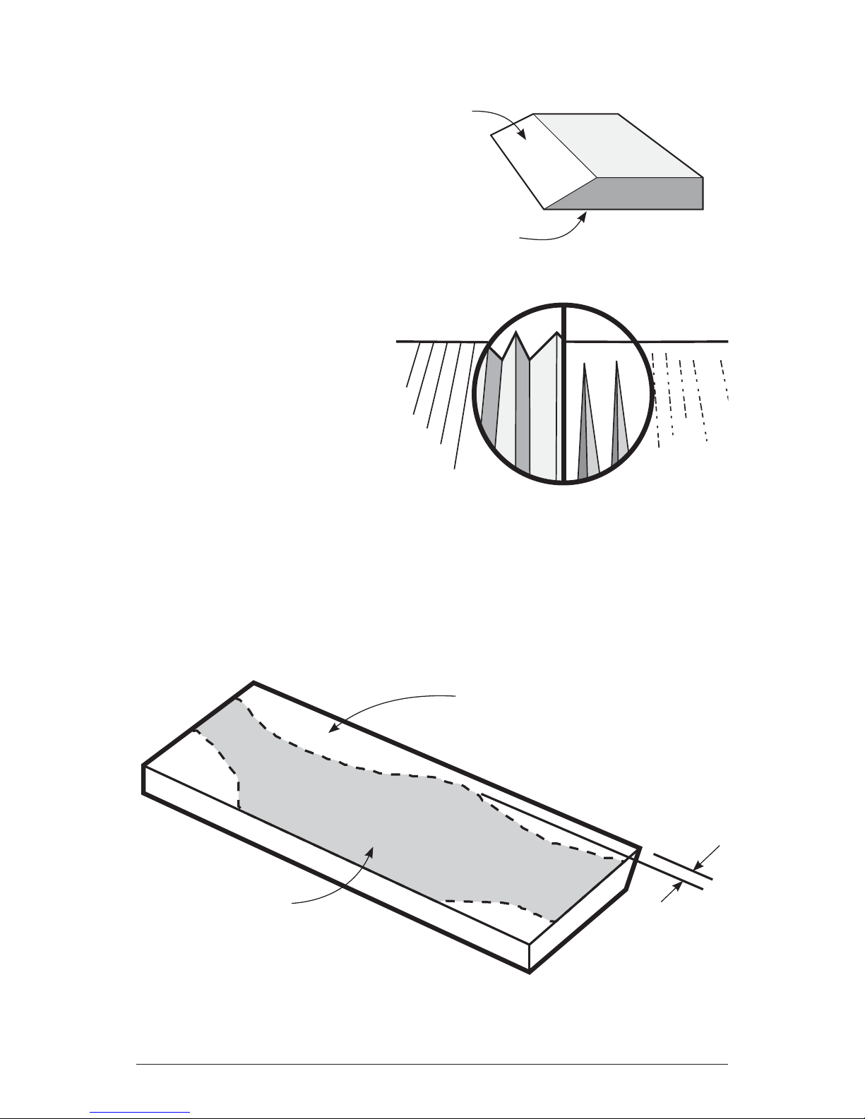
TheVeritas®Jointer Blade Sharpener will jig planer and jointer knives
and hand plane blades up to 8"in width with bevel angles from 25°
to 45°. Sharpening and adding a micro-bevel to wide blades is easy,
repeatable and accurate when using the jointer blade sharpener.
A half sheet of 15 micron, pressure sensitive adhesive (PSA)
backed silicon carbide micro-abrasive is included with your jointer
blade sharpener. Applied to a flat surface, it will quickly sharpen
jointer blades. However, other abrasive sheets may be used, such
as chromium oxide or diamond. Sharpening may even be done on a
traditional bench stone (see Additional Tips, Using a Bench Stone).
Instructions
Prepare the Lapping Surface
The PSA-backed micro-abrasive sheet must be applied to a flat
lapping surface. The infeed or outfeed table of your jointer, or a piece
of 1/4"(or thicker) plate glass, is recommended. For greater safety,
we offer a 1/4"thick, 81/2"× 14"tempered glass plate (05M20.12).
Thoroughly clean the glass (or other true surface) before applying
the abrasive sheet. If you are applying the sheet to glass, create a
thin film of water on the glass. This allows you to adjust the position
of the sheet before sticking it down. Position the sheet at one end of
the glass plate so that it covers the full width. To prevent air or water
bubbles from becoming entrapped, either roll a dowel or draw the
edge of a piece of wood across the sheet (working from the center)
to bond it in place.
Do not use water to apply the micro-abrasive sheet to steel, cast
iron, or any other rust-prone surface. Instead, to prevent air bubbles
from becoming entrapped, make initial contact with one edge of the
sheet. Progressively lay the sheet down, using a straightedge as a
squeegee.
Jointer Blade Sharpener 05M25.01

Lap the Face of the Blade
Since a sharp edge is the
intersection of two smooth
surfaces, the face or
bottom of the blade must
be perfectly smooth in the
area near the cutting edge
before you attempt to hone
the bevel.
Most manufacturers ship
blades with grinding marks
on the face or bottom that,
if not removed, would leave
a series of fine saw teeth on
the tool edge. To avoid these
saw teeth, the face of the
blade must be lapped flat.
The easiest way to lap a new blade is on the 15 micron sheet until
the entire width of the leading edge has a consistent lapping pattern
with the manufacturer’s grinding marks removed at least 1/16"back
from the leading edge of the blade.
Figure 2: Grinding marks on new blades.
Figure 3: Properly lapped face.
Leading edge
lapped flat
Original
grinding marks 1/16"Min.
Bevel
Bottom
or Face
Figure 1: Parts of a blade.
2

Clamping Jointer and Planer Blades
Loosen the thumbnuts securing the three clamps on the jointer blade
sharpener. Position the blade with the bevel facing down under the
short legs of the clamps and lightly tighten the thumbnuts. Turn the
unit over and adjust the blade until it overhangs the edge of the jointer
blade sharpener body by about 1/8"and is approximately parallel as
shown in Figure 4.
Before you fully tighten the thumbnuts, slide them forward until
the clamp springs touch the rear of the blade. This increases the
clamping force, reducing the possibility of the blade shifting during
sharpening (see Figure 4).
Hint: The blade can also be positioned by putting two pennies (one
at each end) under the front of the jointer blade sharpener as it rests
on a flat surface. Let the bevel of the blade slide down to rest on the
surface, then tighten the thumbnuts.
Penny
Figure 5: Positioning blade using penny method.
Figure 4: Clamping jointer/planer blades.
Note: clamp spring
is touching back
edge of blade
Thumbnut
1/8"
3

Your jointer blade sharpener includes two additional thumbnuts.
These serve as position stops to make repeated clamping (such as
when sharpening several blades from the same machine) quick and
easy. Once the first blade is clamped, slide the two stops against
the back of the blade and tighten. When you
change blades, loosen only the clamps
and slide the next blade to be sharpened
against the stops.
Clamping Hand Plane Blades
Loosen the thumbnuts securing the clamps on the jointer blade
sharpener. Turn two clamps sideways so that the short legs point
toward each other. Position the plane blade with the bevel down,
under the short leg of each clamp, and lightly tighten the thumbnuts.
It may be necessary to move one or more of the clamps to any of the
five slots in order to accommodate various blade widths.
Set the blade by eye (as described above) or use the penny method.
Once properly positioned, tighten the thumbnuts.
Adjust the Bevel Angle
With the blade firmly clamped in place and the jointer blade sharpener
resting on a flat surface, note the contact angle of the blade bevel from
the side view. Loosen the locking nut and turn the adjusting screw
until the bevel is parallel to the surface. You can check your bevel-
angle setting by giving the jointer blade sharpener a few strokes on
the abrasive sheet and note if material is being removed from the
heel or the toe of the blade. Make slight adjustments accordingly.
Note that the tip of the adjusting screw is meant to rub on the flat
surface, not the abrasive sheet.
Position Stops
Figure 6: Using the position stops.
4

Once you have the adjusting screw set to the proper angle, tighten
the locking nut against the jointer blade sharpener handle. Continue
to reciprocate the jointer blade sharpener on the abrasive sheet. Hint:
Apply pressure on the push stroke only. This will prevent a thin wire
edge from forming along the leading edge of the blade. Continue
this action until a satisfactory finish has formed on the bevel.
Hone a Micro-Bevel
After basic sharpening, switch to a finer abrasive. Loosen the locking
nut, turn the adjusting screw clockwise a half turn or more and
tighten the locking nut. Note: For every turn of the adjusting screw,
the jointer blade sharpener angle changes by approximately 1/2°.
Reciprocate the jointer blade sharpener (leaning on the push stroke
and letting up on the pull stroke) until a polished line (representing
the micro-bevel) appears over the full length of the blade. Because
this micro-bevel is only at the leading edge, you will remove less
material but arrive at a sharp edge quickly on the finer abrasive. A
wide micro-bevel achieves nothing and will substantially increase
the amount of time spent when you next sharpen the blade.
Adjusting Screw
Locking Nut
Turn adjusting screw
until bevel is resting
flat on surface.
Abrasive
Sheet
Figure 7: Adjusting the bevel angle.
5
Table of contents
Other VERITAS Power Tools manuals