VL-EPU-4460 Reference Manual vii
Figures
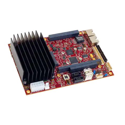
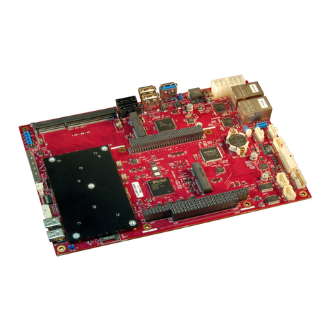
Figure 1. The Condor (VL-EPU-4460) ...........................................................................................................9
Figure 2. Condor (VL-EPU-4460) Block Diagram.......................................................................................11
Figure 3. Condor Dimensions and Mounting Holes ......................................................................................12
Figure 4. Jumpers As-Shipped Configuration................................................................................................15
Figure 5. Top Baseboard Connector Locations.............................................................................................17
Figure 6. Main Power Connector Pin Orientation .........................................................................................18
Figure 7. Location and Pin Orientation of the Battery Connector.................................................................21
Figure 8. VL-CBR-0203 Latching Battery Module.......................................................................................22
Figure 9. Location and Pin Orientation of the CPU Fan Connector..............................................................23
Figure 10. Location of the SATA Connector ................................................................................................25
Figure 11. Location of the USB Ports ...........................................................................................................26
Figure 12. Location of Mini PCIe Sockets....................................................................................................27
Figure 13. Mini PCIe Wireless Status LEDs.................................................................................................30
Figure 14. Location of the SATA/mSATA Activity LED.............................................................................31
Figure 15. Location and Pin Orientation of the User I/O Connector.............................................................32
Figure 16. SPX Connector Location and Pin Configuration .........................................................................34
Figure 17. Location and Pin Orientation of the Serial I/O Connectors..........................................................36
Figure 18. Location of the Mini DisplayPort++ Connectors.........................................................................39
Figure 19. VL-CBR-2032 Mini DisplayPort to VGA Adapter......................................................................40
Figure 20. Location of the LVDS Connectors...............................................................................................41
Figure 21. Location and Pin Orientation of the Ethernet Connector .............................................................45
Figure 22. Onboard Ethernet Status LEDs ....................................................................................................47
Figure 23. VL-CBR-4005B Connectors, Switches, and LEDs......................................................................48
Figure 24. Location and Pin Orientation of the User I/O Connector.............................................................49
Figure 25. Location and Pin Orientation of Auxiliary I/O Connector ...........................................................51
Figure 26. VL-CBR-4005B Dimensions and Mounting Holes......................................................................52
Figure 27. EPU-4460-EAP Dual Core Temperature Relative to Ambient Temperature...............................57
Figure 28. EPU-4460-EBP Dual Core Temperature Relative to Ambient Temperature...............................58
Figure 29. EPU-4460-ECP Dual Core Temperature Relative to Ambient Temperature...............................59
Figure 30. Heat Plate Down ..........................................................................................................................60
Figure 31. Example of Heat Plate Up with a Heat Sink ................................................................................61
Figure 32. Installing the Passive Heat Sink...................................................................................................62
Figure 33. Installing the Heat Sink Fan.........................................................................................................63
Tables
Table 1. Jumper Block Configurations..........................................................................................................15
Table 2. Condor Memory Characteristics......................................................................................................16
Table 3. Main Power Connector Pinout ........................................................................................................19
Table 4. Supported Power States...................................................................................................................20
Table 5. CPU Fan Connector Pinout.............................................................................................................23
Table 6. Mini PCIe Socket 1 / mSATA Socket Pinout..................................................................................28
Table 7. Mini PCIe Card Wireless Status LEDs............................................................................................30
Table 8. User I/O Connector Pinout and Pin Orientation..............................................................................33
Table 9. SPX Connector Pinout ....................................................................................................................35
Table 10 COM1/COM2 Connector Pinout....................................................................................................37
Table 11. Mini DisplayPort++ Connector Pinout..........................................................................................39
Table 12. LVDS Flat Panel Display Connector Pinout .................................................................................42
Table 13. LVDS Backlight Connector Pinout ...............................................................................................44

