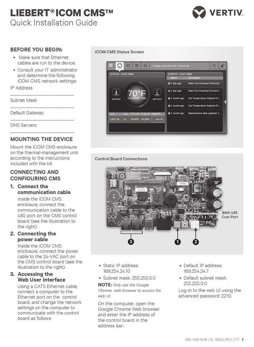
Vertiv Liebert iCOM CMS Installation and maintenance instructions

Liebert®
iCOM CMS™
Installer/User Guide
Intelligent Communication & Monitoring
forLiebertSRC™Mini-SplitSystems

Vertiv™ | Liebert® iCOM CMS™ Intaller/User Guide
Technical Support Site
If you encounter any installation or operational issues with your product, check the pertinent
section of this manual to see if the issue can be resolved by following outlined procedures.
Visit https://www.Vertiv.com/en-us/support/ for additional assistance.
The information contained in this document is subject to change
without notice and may not be suitable for all applications. While
every precaution has been taken to ensure the accuracy and
completeness of this document, Vertiv assumes no responsibility
and disclaims all liability for damages resulting from use of this
information or for any errors or omissions. Refer to other local
practices or building codes as applicable for the correct methods,
tools, and materials to be used in performing procedures not
specifically described in this document.
The products covered by this instruction manual are manufactured
and/or sold by Vertiv. This document is the property of Vertiv and
contains confidential and proprietary information owned by Vertiv.
Any copying, use or disclosure of it without the written permission
of Vertiv is strictly prohibited.
Names of companies and products are trademarks or registered
trademarks of the respective companies. Any questions regarding
usage of trademark names should be directed to the original
manufacturer.

TABLE OF CONTENTS
1 Getting Started with iCOM CMS 5
1.1 Liebert iCOM CMS has 3 Main Features 5
1.2 What Features Would You Like to Use? 5
1.2.1 Access the web-based user interface 5
1.2.2 Access the BMS protocols 5
1.2.3 Access the mobile cloud/mobile app 5
1.3 iCOM CMS web-based user interface 6
1.3.1 Setpoint and Sensor status 8
1.3.2 Unit Status 8
1.4 Logging-on to iCOMCMS and Unlocking controls 9
1.4.1 Powering-on the cooling unit 9
1.4.2 Powering-off the cooling unit 9
1.4.3 Logging out 9
1.5 Setting general display properties 9
1.6 Setting the date and time 10
1.7 Searching 10
1.8 Using Context-sensitive Help 11
1.9 About iCOM CMS version 11
1.10 Accessing the User, Service and Advanced functions 11
2 User Operation 15
2.1 Viewing setpoints for the cooling unit 15
2.2 Viewing the event log for a cooling unit 15
2.3 Viewing cooling-unit alarms 16
2.3.1 Acknowledging alarms 17
3 Service and Advanced Operation 19
3.1 Editing setpoints for the cooling unit 19
3.1.1 Setting-up Auto Run Mode 20
3.2 Managing Alarm and Warning Notifications 21
3.2.1 Enabling alarm/warning notifications and editing settings 21
3.3 Maintenance scheduling and component run hours 22
3.3.1 Setting Maintenance Dates 22
3.4 External Monitoring and Building-management systems 22
3.4.1 Modbus RTU Set Up 23
3.4.2 Modbus TCP Set Up 23
3.4.3 SNMP Set Up 24
3.5 Connection Settings 25
3.6 Backing-up and Restoring settings 26
3.6.1 Backing-up iCOM CMS settings 26
3.6.2 Restoring iCOMCMS settings 26
3.6.3 Exporting iCOMCMS settings 26
Vertiv | Liebert® iCOM CMS™ Intaller/User Guide | 3

3.6.4 Importing iCOMCMS Settings 27
3.6.5 Resetting hardware to factory defaults 27
3.7 Updating iCOMCMS firmware 28
3.7.1 Firmware update using USB drive 29
3.7.2 Firmware update using drag-and-drop 29
3.8 Managing Access Permission and PINS 30
3.9 Generating a Diagnostics Report 30
3.10 Setting unit name, location and serial number 31
3.11 Setting the iCOMCMS Name 31
3.12 Setting the Managing Mode 32
3.13 Managing SSL Certificates 32
3.13.1 Generating a Certificate Signing Request 32
3.13.2 Generating a Self-signed Certificate 33
4 Installing and Connecting iCOMCMS 35
4.1 Mounting iCOMCMS on Thermal-management Unit 35
4.2 Connecting the SRC andCMS ControlBoardswiththeModbusGateway 36
4.3 Setting up Communication withtheWeb-basedUserInterface 39
4.4 Set the Managing Mode to SRC 40
4.5 Enable the Connected SRC Units 40
4.6 Registering with the Administration Portal toAllowMobile-appUsers Access 41
4.7 Setting Up Network Communication 41
4.8 Setting Up BMS serial communication 42
Appendices 43
Appendix A: Technical Support and Contacts 43
Vertiv | Liebert® iCOM CMS™ Intaller/User Guide | 4

1 GETTING STARTED WITH ICOM CMS
The web-based user interface for iCOMCMS offers the highest capability for unit control, communication,
and monitoring of Liebert® Thermal Management units. It is available factory-installed on new units and
assemblies or may be retrofitted in existing units. For details on first-time set-up and retro-fit installation,
see Installing and Connecting iCOMCMS on page 35.
1.1 Liebert iCOM CMS has 3 Main Features
•A web-based user interface providing remote connectivity to a unit-level display with full
read/write capabilities.
•BMS connectivity via Modbus RTU, Modbus TCP/IP and SNMP.
•Mobile cloud/Mobile app access to view status and notification information on a mobile device.
NOTE: You can control the unit using the web-based UI, including unit on/off, setpoints, and alarm set-
up. The mobile app, however, does not allow unit control. It is a read-only interface for notifications.
1.2 What Features Would You Like to Use?
You can use one or all of these features, and the following sections provide an outline of the steps to set-
up and get started using each one.
1.2.1 Access the web-based user interface
Place iCOMCMS on your corporate network by configuring the network settings using the Connection
Settings menu. See Connection Settings on page 25.
Once set-up, everyone using a computer with corporate-network access and provided with the assigned
IP address can open the web UI in a web browser.
1.2.2 Access the BMS protocols
To configure communication with your building-management system, use the BMS Setup menu. See
External Monitoring and Building-management systems on page 22.
1.2.3 Access the mobile cloud/mobile app
Place iCOMCMS on your corporate network by configuring the network settings using the
ConnectionSettings menu. See Connection Settings on page 25.
Then, register the iCOMCMS cooling unit using the Cloud Setup menu. See Registering with the
Administration Portal toAllowMobile-appUsers Access on page 41.
•Once the unit is registered, the e-mail address you used to register the device will receive a
password-change e-mail with the credentials to log-in to the iCOMCMS Administration Portal
(www.icomcms.com) and the mobile app.
1 Getting Started with iCOM CMS 5

•Visit the Administration Portal at icomcms.com, and log-in to manage the registered devices
and mobile-app users as follows:
•Create a division.
•Create a building and assign the building to a division.
•Assign the registered iCOMCMS unit to a building.
•Create users, define the user’s role (Administrator, Mobile-app only), set-up e-mail or
SMS-text notifications, and assign buildings to the user, which determines what units
they can view in the mobile app.
•The mobile-app users will get an e-mail with log-in credentials, and can download the
iCOMCMS mobile application and log in to receive notifications.
1.3 iCOM CMS web-based user interface
The web-based user interface speeds set up and installation and simplifies control of Liebert® cooling
units.
•User, service and advanced menus are password-protected to prevent unauthorized changes
to cooling-unit operation. See Logging-on to iCOMCMS and Unlocking controls on page 9.
•iCOMCMS ships with default settings for efficient and effective operation of most cooling-units
and is easily configured to meet any need.
•iCOMCMS requires a Google Chrome web browser version 50.0.xx or higher.
Figure 1.1 on the facing page, shows the controls and options available on the main display.
Vertiv™ | Liebert® iCOM CMS™ Intaller/User Guide
6

Figure 1.1 iCOM CMS web-based user interface
ITEM DESCRIPTION
1 Menu icon. When unlocked, displays set-up, control options and menu depending on the password level used.
2Status view. When you log on, the iCOMCMS-controlled units and their status are listed on the main display. Clicking the
status icon toggles between the status and alarm summary.
3
Settings view. When selected, the settings options are listed on the main display. Options are:
•Display Preferences, see Setting general display properties on page 9.
•Date/Time Setup, see Setting the date and time on page 10.
•iCOM-CMS settings are listed when you are logged-in at the “advanced” level, see:
•Setting the iCOMCMS Name on page 31.
•Setting the Managing Mode on page 32.
•Managing SSL Certificates on page 32
4
Service view. When selected, the last and next preventive maintenance (PM) are listed next to the connected units.
SeeMaintenance scheduling and component run hours on page 22.
You must be logged-on at the “Service” or “Advanced” level to access the service icon.
See Logging-on to iCOMCMS and Unlocking controls on page 9.
5
Advanced view. When selected, advanced-level options are available on the menu.
You must be logged-on at the “Advanced” level to access the advanced icon.
See Logging-on to iCOMCMS and Unlocking controls on page 9.
6 Search. Opens the “search” term-entry box. See Searching on page 10.
7Lock/Unlock. Indicates that the options/menus at the level at which you are logged-on (user, service or advanced) are
accessible. See Logging-on to iCOMCMS and Unlocking controls on page 9.
1 Getting Started with iCOM CMS 7

ITEM DESCRIPTION
8Setpoint and Status summary. Summary display of setpoints and environmental conditions of the unit. See Setpoint and
Sensor status on page 8.
9Secondary-content panel. When accessing settings/configuration via the menus, the settings display in the right,
“secondary” panel.
10 Primary-content panel. When accessing settings/configuration via the menus, a list of options/categories display in the
left, “primary” panel.
11 Unit list. A list of monitored units. Clicking a unit displays the setpoint and status summary for that unit.
1.3.1 Setpoint and Sensor status
The dial in the status panel displays setpoints and environmental conditions for the unit at a glance.
Figure 1.2 Status dial
ITEM DESCRIPTION
1 Temperature-sensor reading. Current temperature reading at the unit.
2 Temperature setpoint. Current temperature setpoint.
3 Operating mode. Current operating mode of the unit.
4 Fan mode. Current operating mode of the fan.
1.3.2 Unit Status
The unit status list in the main status panel displays unit-specific settings and parameters at a glance.
The list shows current temperature-sensor reading and the high/low temperature readings for each
monitored unit. Selecting a unit in the list displays more information about that unit in the status dial, see
Figure 1.2 above.
Vertiv™ | Liebert® iCOM CMS™ Intaller/User Guide
8

1.4 Logging-on to iCOMCMS and Unlocking controls
The factory-default password for user, service and advanced login are provided. We recommend you
change passwords as necessary to prevent unauthorized changes. See Managing Access Permission and
PINS on page 30.
•Default User password = 1490
•Default Service password = 5010
•Default Advanced password = 2210
To log-on and unlock iCOMCMS:
1. Open the iCOMCMS web interface in your browser.
The log-in screen opens.
2. Type the password, and click Sign In.
Depending on the user level selected, the user/service/advanced options are accessible. See
Accessing the User, Service and Advanced functions on page 11.
1.4.1 Powering-on the cooling unit
1. In the unit list on the status panel, click .
The POWER UNIT CONTROL dialog opens.
2. Click On.
The cooling unit starts.
1.4.2 Powering-off the cooling unit
1. In the unit list on the status panel, click .
The POWER UNIT CONTROL dialog opens.
2. Click Off.
The cooling unit powers-off.
1.4.3 Logging out
To log-out, click the lock icon.
The log-in screen displays.
1.5 Setting general display properties
1. On the menu bar, click SETTINGS, then Display Preferences in the settings list.
The DISPLAY PREFERENCES panel displays.
2. Select the settings and click Save.
•Click Cancel to discard the changes.
1 Getting Started with iCOM CMS 9

Display-preferences fields
Theme
Selects the color theme for the display.
Measurement System
Selects the units of measurement.
Inactivity Timer
Time to elapse before display logs-off.
Date Format
Display format for the date.
Time Format
Display format for the time.
1.6 Setting the date and time
The correct date and time is critical for warnings, alarms, and scheduling.
1. On the menu bar, click SETTINGS, then Date/Time Setup in the settings list.
The DATE/TIME SETUP panel displays.
2. Select the settings.
3. Click Save.
•Click Cancel to discard the changes.
Date/Time set-up options
Time Zone
Selects the time zone.
NTP Server #X
When NTP is enabled, the address of the server(s) to which the unit refers for the time protocol,
where X=designates a reference number for the server.
1.7 Searching
Use the display search to find the location of settings options.
1. On the menu bar, click SEARCH.
The term-entry box opens.
•Click Search again to close the term-entry box.
2. Type the term and press Enter.
A list of locations that contain the searched term opens.
3. Click an item to open the panel for the selected location.
Vertiv™ | Liebert® iCOM CMS™ Intaller/User Guide
10

1.8 Using Context-sensitive Help
Clicking the Help icon, , on the right-hand side of the display opens the Help drawer with information
about the panel or dialog currently on the display. You can use search in the Help to find further
information.
To close the Help drawer, click the close arrow, again.
1.9 About iCOM CMS version
The version, build, and other firmware information may be helpful when servicing or troubleshooting.
1. Click ,
The menu opens.
2. Click About.
The ABOUT panel opens.
1.10 Accessing the User, Service and Advanced functions
The iCOMCMS operating functions that monitor and control a cooling unit are accessed via the icons in
the header and the menus.
NOTE: You must be logged-in with the appropriate level and password to access the menu options for
user-, service- and advanced-specific functions. See Logging-on to iCOMCMS and Unlocking controls
on page 9.
To access menu functions:
Click the menu icon, .
Depending on the function level at which you are logged-in, the menu opens. The following lists describe
the available options on each menu.
User-level menu options
Setpoints
Opens the SETPOINTS panel. See Viewing setpoints for the cooling unit on page 15.
Event Log
Opens the EVENT LOG panel. See Viewing the event log for a cooling unit on page 15.
About
Opens the ABOUT panel. See About iCOM CMS version on page 11.
Support & Services
Opens the SUPPORT & SERVICES panel.
1 Getting Started with iCOM CMS 11

Service-level Menu Options
Setpoints
Opens the SETPOINTS panel. See Editing setpoints for the cooling unit on page 19.
Set Alarms
Opens the SET ALARMS panel. See Managing Alarm and Warning Notifications on page 21.
Event Log
Opens the EVENT LOG panel. See Viewing the event log for a cooling unit on page 15.
BMS Setup
Opens the BMS SETUP options:
•Modbus—See Modbus RTU Set Up on page 23.
•SNMP—See SNMP Set Up on page 24.
Cloud Setup
Opens the CLOUD SETTINGS panel. See Registering with the Administration Portal
toAllowMobile-appUsers Access on page 41.
Connection Settings
Opens the DISPLAY CONNECTIONS panel. See Connection Settings on page 25.
Settings Management
Opens the SETTINGS MANAGEMENT options:
•Backup & Restore—See Backing-up and Restoring settings on page 26.
•Import & Export—See Importing iCOMCMS Settings on page 27, and Exporting iCOMCMS
settings on page 26.
•Factory Reset—See Resetting hardware to factory defaults on page 27.
Load Firmware
Opens the FIRMWARE UPGRADE PARAMETERS panel. See Updating iCOMCMS firmware on page
28.
About
Opens the ABOUT panel. See About iCOM CMS version on page 11.
Support & Services
Opens the SUPPORT & SERVICES panel.
Vertiv™ | Liebert® iCOM CMS™ Intaller/User Guide
12

Advanced-level Menu Options
Setpoints
Opens the SETPOINTS panel. See Editing setpoints for the cooling unit on page 19.
Set Alarms
Opens the SET ALARMS panel. See Managing Alarm and Warning Notifications on page 21.
Event Log
Opens the EVENT LOG panel. See Viewing the event log for a cooling unit on page 15.
BMS Setup
Opens the BMS SETUP options:
•Modbus—See Modbus RTU Set Up on page 23.
•SNMP—See SNMP Set Up on page 24.
Cloud Setup
Opens the CLOUD SETTINGS panel. See Registering with the Administration Portal
toAllowMobile-appUsers Access on page 41.
Connection Settings
Opens the DISPLAY CONNECTIONS panel. See Connection Settings on page 25.
Settings Management
Opens the SETTINGS MANAGEMENT options:
•Backup & Restore—See Backing-up and Restoring settings on page 26.
•Import & Export—See Importing iCOMCMS Settings on page 27, and Exporting iCOMCMS
settings on page 26.
•Factory Reset—See Resetting hardware to factory defaults on page 27.
Load Firmware
Opens the FIRMWARE UPGRADE PARAMETERS panel. See Updating iCOMCMS firmware on page
28.
Manage Passwords
Opens the MANAGE PASSWORDS panel. See Managing Access Permission and PINS on page 30.
About
Opens the ABOUT panel. See About iCOM CMS version on page 11.
Support & Services
Opens the SUPPORT & SERVICES panel. Includes the option to create a diagnostics report to help
with technical-support calls. See Generating a Diagnostics Report on page 30.
1 Getting Started with iCOM CMS 13

Vertiv™ | Liebert® iCOM CMS™ Intaller/User Guide
14
This page intentionally left blank

2 USER OPERATION
2.1 Viewing setpoints for the cooling unit
NOTE: User-level access allows only viewing of setpoints. To adjust setpoints, you must have service-
or advanced-level access. See Editing setpoints for the cooling unit on page 19.
To view the setpoints:
1. Click > Setpoints.
The SETPOINTS panel opens.
2. Click the name of the unit for the setpoints you want to see.
The detail panel displays the setpoints for that unit.
Setpoints—user level
Temperature
Temperature that the unit maintains via cooling/reheat.
Fan Speed
Indicates the selected fan speed.
Run Modes
Indicates the operating mode of the unit.
2.2 Viewing the event log for a cooling unit
The event log is a list by date/time, unit, event type for all generated events and alarms and includes the
PIN ID for user-generated events and comments. Selecting an event log displays details about the event.
To view the event log:
1. Click > Event Log.
The EVENT LOG opens.
2. Click an event to display the detailed information.
Event-log fields
When
The date and time the event occurred.
2 User Operation 15

Unit
The cooling unit to which the event is associated.
Description
Description of the event.
PIN ID
The name of the user that made a user-generated event or comment.
Event details
Date/Time
The date and time the event occurred.
Unit
The cooling unit to which the event is associated.
Description
Description of the event.
PIN ID
The name of the user that made a user-generated event or comment.
2.3 Viewing cooling-unit alarms
The ALARMS SUMMARY lists active alarm and warning events for the cooling unit.
To view the alarm summary:
1. On menu bar, click STATUS, to toggle between the status and alarm summaries.
The ALARMS SUMMARY displays in the primary panel, and the ALARMS list displays in the
secondary panel.
2. Click a unit to display the alarms list for that unit.
3. Click an alarm to display the ALARM DETAILS panel, described in Alarm/Warning detail fields
on page 17.
Alarm list fields
When
Time elapsed since the event was logged.
Description
Description of the event.
Vertiv™ | Liebert® iCOM CMS™ Intaller/User Guide
16

2.3.1 Acknowledging alarms
Once acknowledged, an event remains active until the situation that triggered the event is resolved.
NOTE: The High Water alarm event and the Smoke Detected alarm event (if smoke-detector option is
included) automatically power-off the cooling unit.
To acknowledge an alarm:
1. On the ALARMS list, click an alarm/warning.
The alarm detail panel displays.
2. On the alarm-detail, click Acknowledge.
NOTE: Acknowledging alarm events does not clear them. To clear an issue, it must be corrected, reset
automatically by the controller, or reset manually.
Alarm/Warning detail fields
Event Type
The type of event.
Status
Current status of the event.
Date/Time
Date and time the event was logged.
Duration
Length of time the event is active.
2 User Operation 17

Vertiv™ | Liebert® iCOM CMS™ Intaller/User Guide
18
This page intentionally left blank

3 SERVICE AND ADVANCED OPERATION
NOTE: With the exception of managing passwords, which is only available to the advanced-level user,
the service and advance menu options are the same.
3.1 Editing setpoints for the cooling unit
Setpoints are the means by which cooling-unit operation is controlled.
NOTE: Setpoint adjustment is only available via the web-based UI (and the wall-mounted controller).
You cannot modify setpoints using the mobile app.
NOTE: The default minimum difference between heating and cooling setpoints is 5°F (2°C), and does
not allow the heating and cooling setpoints to be set inside this differential. To select setpoints for that
do not automatically adjust to the minimum difference, this differential must be zero. We recommend
that you set the differential to zero at system start-up. See Setting the Temperature Differential on
page 20.
To edit the setpoints:
1. Click > Setpoints.
The SETPOINTS panel opens.
2. Adjust the setpoint options, then click Save.
The setpoint is updated.
•Click Cancel to discard the changes.
Setpoint options
Temperature
Temperature that the unit maintains via cooling/reheat.
Fan Speed
Selects the fan speed.
NOTE: Auto fan-speed may only be set via the wall-mounted thermostat.
Run Modes
Selects the operating mode of the unit. Options are:
•Cooling
•Heating
•AI (Auto). See Setting-up Auto Run Mode on page 20.
•Fan
•Dehumidify—Not Supported. Do Not Use.
3 Service and Advanced Operation 19

3.1.1 Setting-up Auto Run Mode
To properly navigate communication between the web UI and the wall-mounted thermostat controls, a
2-step procedure is required:
•At the thermostat, set the temperature differential to 0º (zero).
•On the web UI, set the heating and cooling setpoints, then the AI run mode.
Setting the Temperature Differential
The default minimum difference between heating and cooling setpoints is 5°F (2°C), and does not allow
the heating and cooling setpoints to be set inside this differential. To select setpoints for that do not
automatically adjust to the minimum difference, this differential must be zero.
NOTE: If you are having an issue with discrepancies in the setpoints and readings, and setting the
temperature differential does not help, please contact technical support at 1-800-543-2778.
1. At the wall-mounted thermostat, open the flip door and press twice until flashes in
the Function Settings section of the display.
2. Press to set the differential to 0°, then press .
3. Press to exit the function set-up.
Setting Heating, Cooling Setpoints and AI Run Mode
Before selecting AI (Auto) run mode, you must set the heating and cooling setpoints to the same value.
You must be in the run mode of the setpoint when setting it.
1. Make sure the minimum difference between setpoints is 0°. See Setting the Temperature
Differential on page 20.
2. Select heating run mode and set the heating setpoint on the web UI:
•Click > Setpoints, then select the unit to configure.
•In Run Mode, select Heating.
•In Fan Speed, select the fan speed to use.
•In Temperature, select the temperature setpoint.
•Click Save.
3. Select cooling run mode and set the cooling setpoint on the web UI:
•In Run Mode, select Cooling.
•In Fan Speed, select the fan speed to use.
•In Temperature, select the temperature setpoint.
•Click Save.
4. In Run Mode, select AI, then click Save.
The status dial displays “AI” for about 2minutes, and the wall-mounted thermostat is un-
responsive to button presses during this time while the configuration is communicating. After
that, the web UI displays the run mode currently in use, and the wall-mounted thermostat
indicates “AUTO” mode.
Vertiv™ | Liebert® iCOM CMS™ Intaller/User Guide
20
Table of contents
Other Vertiv Control System manuals
Popular Control System manuals by other brands

Modine Manufacturing
Modine Manufacturing Atherion MPR System manual

NuTone
NuTone AD-500 Facility Manager’s Guide

Monitech
Monitech ML121QT1400 install guide

Sony
Sony JumboTron JTC-C200 operating instructions

TECSYSTEM
TECSYSTEM FO 935 ETH instruction manual

Intelligent Motion Systems
Intelligent Motion Systems MicroLYNX-4 Quick manual