Vescent D2-135 Manual

2022/03/09 21:11 1/4 Quick Setup Instructions (Offset Phase Lock D2-135)
Product Manuals - https://www.vescent.com/manuals/
Quick Setup Instructions (Offset Phase Lock
D2-135)
Please refer to the Quick Setup Instructions for setting up the electronics modules and connecting the
Laser Controller to the Lasers.
At this point you should have two lasers temperature stabilized and running at their operating current.
The two lasers should be within a few GHz of the same frequency of each other. (If unsure of the laser
frequency, you can use a spectroscopy module to get one laser on transition and then temporarily
move the spectroscopy module to the other laser to get it near the same transition.)
D2-150 Alignment
This section assumes you are using the D2-150 Heterodyne Module to obtain an optical beat note
between two lasers. If you have obtained an optical beat note by other methods, please skip this
section.
Fig. 1:
Schematic drawing of the laser alignment in to the
D2-150 Heterodyne Module.
Place the two lasers and the D2-150 as
shown in figure 1: the two lasers oriented
90° relative to each other and both pointing
at the D2-150. Take the top off the D2-150
and place it such that the beams of both
lasers hit the center of the first beam splitter
that they encounter. There are 3 adjustable
beam splitters in the D2-150: two for
aligning one laser, and one for aligning the
other laser. In figure 1 the master laser is
the laser with only one adjustment because
it passes straight-through the second beam
splitter on its way to fiber, while the slave
laser reflects at 90° off of two beam splitters.
It is important to align the laser with only
one adjustment stage first (the master laser
in the figure).
First Laser Alignment
Use a power meter to measure the power out from the fiber connected to the D2-150. Block the laser
that has two adjustments and measure the power from the laser with one adjustment that gets
coupled into the fiber. Use the two adjustments on the beam splitter that affects the laser position to
maximize the power into the fiber. If you cannot measure any light from the fiber, it is often helpful to
put light into the fiber (opposite direction from how the system operates) and see how well that light
gets back to the laser. Adjust the same beam splitter so the light is aimed directly at the laser source.

Last update: 2021/08/26 14:26 d2:quick_start_opls https://www.vescent.com/manuals/doku.php?id=d2:quick_start_opls&rev=1438876076
https://www.vescent.com/manuals/ Printed on 2022/03/09 21:11
This should get the alignment close enough to measure the power in the fiber to use for further
optimization. Aim for 500 μW of power although a few hundred microwatts should be sufficient.
<span style="color:red">The detector in the D2-160 or D2-135-FC can be
damaged by more than 1 mW input power, so be careful not to couple in too
much light.</span>
Second Laser Alignment
Once you have at least a few hundred microwatts of power from the first laser coupled into the fiber,
the next step is to overlap the lasers with two adjustments to the second laser. Unblock the second
laser. The last beam splitter has two outputs: one goes to the fiber, the other to an exit port. This port
is for alignment and portions of both lasers will pass out of this port. Looking at this output close to
the D2-150 and far from the D2-150, one can match the position and angle of the second laser to the
first. When doing the alignment, adjust the beam splitter close to the fiber when looking at the beams
far from D2-150 and use the other beam splitter when looking close to the D2-150. By iterating
adjustments back and forth, you can converge on a nice alignment of the laser. At this point you
should be coupling a few hundred microwatts of power from the second laser into the fiber. If you are
not, try tweaking the beam splitter closest to the slave laser input beam and then repeat the
alignment procedure. Once this is done, you are ready to look for a beat note.
Finding a Beat Note
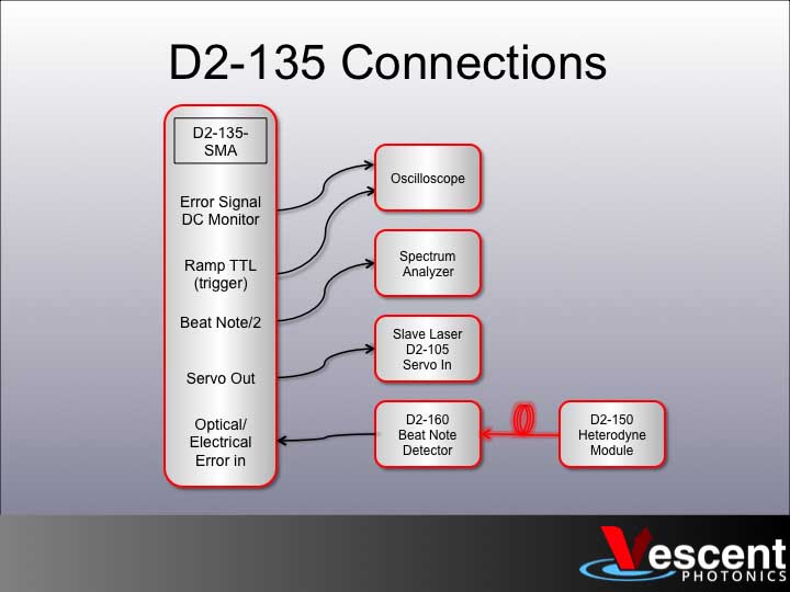
Fig. 3:
Initial
electric
al
connec
tions to
D2-135
. (As
shown
for
D2-135
-SMA.
For
D2-135
-FC,
connec
t optical output of D2-150 directly to SC fiber input on face of
D2-135.)
Plug the fiber into either the
D2-160 or D2-135-FC. If using
the D2-160, use a short RF
SMA cable to connect the
D2-160 to the D2-135-SMA.
Look at the D2-135's Beat
Note div/2 monitor on a
spectrum analyzer. You
should see a beat note at half
the frequency difference
between the two lasers. You
may need to tweak the laser
current on one laser to make
sure the frequency difference
is in range. Once you see a
beat note, adjust the laser
frequency until the beat note
starts to broaden or
disappear. When that
happens, park the laser
where the beat note starts to
degrade and tweak the
alignment of the 3 beam
splitters until the beat note
looks good. Repeat until you
have the desired frequency
range (typically ~10 GHz).

2022/03/09 21:11 3/4 Quick Setup Instructions (Offset Phase Lock D2-135)
Product Manuals - https://www.vescent.com/manuals/
D2-135 Locking
Getting a phase lock can be tricky, as the servo feedback must be pretty well optimized to your laser
to get a phase lock. The narrower the linewidth of the laser and the higher the bandwidth of the laser,
the easier it is to get a phase lock. The first step is to get an error signal with a steep slope at the
desired offset frequency and then a basic lock.
Connect the D2-135's Servo Out to the Servo In on your Laser Controller to sweep the slave laser's
frequency. (Refer to figure 3 for making electrical connections to the D2-135.) Connect the Ramp TTL
on the D2-135 to the trigger on your O-scope and view the Error In Monitor to the O-scope. Set the
D2-135 to N=16, VCO Low mode, put the Servo in Ramp mode and by tweaking the laser current, you
should see the Error In Monitor look something like what is shown in figure 4.
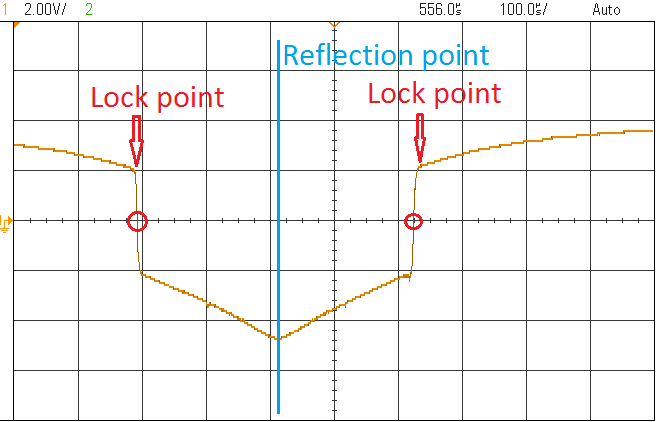
Fig. 4:
Sample
Error
Signal
when
sweepi
ng one
laser.
Reflecti
on
point
shown
in blue,
two
lock point shown in red.
The reflection point on the
Error Signal is where the two
lasers are at the same
frequency. The Error Signal is
a even function of offset
frequency (Error(Δf) = Error(-
Δf)), so there is a reflection
point about Δf=0. The sharp
slope to the left or right of the
Δf=0 point is the lock point
and can be adjusted by
changing the VCO frequency.
Which of the two lock points
the laser will lock to will
depend on the gain sign.
Center the O-scope on one of
the lock points and turn down
the ramp amplitude. Flip the
D2-135 Servo to Lock mode. If
the Servo Output jumps to
+/-10V, repeat with the
opposite gain sign. At this
point, you should have a lock
that is holding the offset
frequency to a specific value.
You may be be significantly
broadening the laser because
the servo is oscillating, but
you have a basic lock.
Optimizing the Lock
The first step is to optimize the gain.
Look at the Error In Monitor and turn
down the gain to minimize the RMS
noise on the Error In Monitor. At this
point you should be able to see the

Last update: 2021/08/26 14:26 d2:quick_start_opls https://www.vescent.com/manuals/doku.php?id=d2:quick_start_opls&rev=1438876076
https://www.vescent.com/manuals/ Printed on 2022/03/09 21:11
Fig. 5:
Beat note when locked with coherent peak showing a phase
lock.
beat note with the Beat Note (div 2)
monitor on a spectrum analyzer with
a 100 MHz span. You can try to
further optimize the gain by looking
at the beat note monitor and trying
to minimize the width of the beat
note (or if there is a phase lock,
maximize the amplitude of the
coherent peak). The next step is to
optimize the feedback. It is
recommended starting with the ωHF in
the off position, ωI at 16 kHz, and ωD
at 64 kHz. Generally, leave ωHF off
and adjust ωD, ωI, diff gain and
overall gain while monitoring the
beat note to see if the lock is getting
better as you make adjustments.
Look for a narrow peak coming out of
the center of the beat note, as shown
in figure 5.
From:
https://www.vescent.com/manuals/ - Product Manuals
Permanent link:
https://www.vescent.com/manuals/doku.php?id=d2:quick_start_opls&rev=1438876076
Last update: 2021/08/26 14:26
Other Vescent Lock manuals


