manuals.online logo
Brands
  1. Home
  2. •
  3. Brands
  4. •
  5. Vesta
  6. •
  7. Security System
  8. •
  9. Vesta Smart Home Security Alarm System User manual

Vesta Smart Home Security Alarm System User manual

1
1
IP Installation Guide
Vesta Series
Smart Anytime Safe Anywhere
IP/GSM + GPRS ALARM SYSTEM
Home Automation Intelligence
2
2
Content
Topic Page
Introduction 1
1A Location Planning - House Mapping 2-3
2A Unpacking all the parts - Main Vesta Controller 4
2B Devices 5
2C Devices continue 6
2D Understanding Extern Siren 7
3A Initial physical setup and Connection to Cloud Portal 8
3B Introduction to home and cloud Portal 9
3C Accessing home Portal Server 10
3D/3E/3F Account Registration 11-12-13
3G Registration MAC Address in Cloud Portal 14
3H/3I Log - IN Cloud Portal 15 - 16
3J/3k Portal Dashboard - System Area 17 - 18
3L Portal Dashboard - Sensors explained 19
3M Portal Dashboard - Automation explained 20
3N Portal Dashboard - Automation HVAC explained 21
3O/3P/3Q Portal Dashboard - Automation HVAC 22-23-24
3R Portal Dashboard - Automation - Room 25
3S/3T Portal Dashboard - Automation - Groups & Scene 26 - 27
3U Portal Dashboard - Automation - Rules 28
3V/3W/x/Y Portal Dashboard - Automation - Rules 29-30-31-32
3Z Portal Dashboard - IP Camera (CAM) 33
3# Portal Dashboard - IP Cam & All Events 34
3* Portal Dashboard - Master Installer Code and Device
Setting
35
4A/B/C/D/
E /F/G
Enrolling Devices to Main Controller 36-37-38-39-40-41-42
4H Adding & Editing Uses Code 43
4I Main Vesta Controller 44
5A VESTA HOME - 5 Smart Phone (Execute the APP) 45
5B/5C Automation : Scene - Room - Group - Automation De-
vice - Rules
46 - 47
5D Automation : Rule - Camera - Event - Reporting 48
5E Miscellaneous 49
Vesta Australia Smart Home Security Alarm System
Installation - Programming - Operating
Introduction
•
.
•
•
•
.
•
•
•
•
•
1
4
4
1A Location Planning
Work out the best places to locate the devices for maximum protection. Having chosen the locations
do not mount at this stage.
Door & window
Contacts
Motion sensor (PIR)
Keypad - Front
entry & garage
Diagram illustration is an example only
2
5
5
1B Location Planning continue
Choosing Location .—
unit and must not be mounted on or near
large
ground floor can be armed when going to bed at night
•
entry/exit point
reliable operation.
•Mount in the middle of the ceiling at the top of a stairwell, or on the centre of
hallway ceilings where smoke would most likely be detected.
• Do not mount in corners or above cooking appliances and heaters.
• Install additional detectors if the rear doors preventing smoke from reaching detectors.
Choose a position on an external wall where the siren would be most prominent. Mount as high as
possible, out of easy reach.
Select a door that will be the main point of entry and exit, usually your front door.
• rear door entry door thought a garage entry, garage roller door. Also consider key windows.
3
6
6
2A Unpack all the parts
Tamper switch Internet
connection
4G Sim Slot GSM Z-Wave USB MAC Address Default Reset
12Volt Plug Pack
Internet lead x 1
12 Volts DC Plug Pack Internal Siren
Unpack the kit content on a table. Remove the mounting back plate from the control unit by unscrewing the two
bottom screws and top screws. Open back plate from Main Controller unit to expose the connections as illustrated in
the diagrams above. A power adaptor is supplied that plugs into the main wall socket and control unit. Plug in the
power adaptor and connect the box to your internet router using the cable provide. In addition to the power
adapter, there is a rechargeable battery inside the control unit that serves as a backup in case of a power
failure. A fully charged battery can provide backup power for a period of at least 10 hours. It takes approximately
72 hours fully charge the battery.
LED Indicators
LED Indicators
Control Unit
TOP LED 1 (Panel Status)
RED = Solid ON : Alarm is ARM
RED = Flashing : Home is ARM
GREEN = Solid ON : Alarm Disarm
GREEN = Flashing : Learning Mode
Middle LED 2 (Alarm & Fault Status)
RED = Alarm been Triggered
RED = Flashing On going Alarm Event
YELLOW = DEVICE Fault Temper / LOW Battery
YELLOW- Flashing = Mains power Failed
BOTTOM LED 3 (Operation Status)
YELLOW ON = Network Problems
YELLOW Flashing = Disconnected from VESTA Cloud Server
GREEN ON = All SYSTEM NORMAL
VESTA Main Controller
Main home
Router / Internet Connection
Data cable supplied
VESTA Power Plug Pack
Battery
backup
switch
4
7
7
2B Unpack all the parts
PIR - Motion detectors
1 Pull out the plastic
pull tab on the back of
the PIR. This will
activate the batteries.
Learn/Testing
Button
Wireless Keypad
1 Pull out the plastic
pull tab on the back of
the Keypad. This will
activate the batteries.
Press * & # together
For 1 sec Learn/Testing
Button
Remote—Fobs
Press Arm
Button for 1 sec
Installing / replacing Batteries in the Motion PIR.
Step 1. undo the screw at the button of the sensor.
Step 2. insert battery supplied (EL123)
Step 3. return the back and re –recrew cover.
Step 4. Press learning/Testing button to active Sensor. (red light
Flash)
1 x Screw
Installing / replacing Batteries in the Keypad
Step 1. undo the screw at the button of the keypad
Step 2. insert AA battery EL123
Step 3. return the back and re –recrew cover.
Step 4. Press learn/Testing *& # button to active Keypad
Installing / replacing Batteries in the Remote Key fob
Step 1. Open Battery Compartment using coin by turning cover in the
direction of the big arrow
Step 2. insert battery
Step 3. return the back and re –screw cover.
Step 4. Press Arm Button to activate
5
8
8
2C Unpack all the parts
Door/ Window Magnetic Contact
Learn/Testing
Button
Installing / replacing Batteries in the Door /window contacts
Step 1. undo the screw at the button of the contact
Step 2. insert AAA battery supplied
Step 3. return the back and re - screw cover.
Step 4. Press learning/Testing button to active Sensor. (red light
Flash)
Step 5. Installing door magnet on the side marked on the door
contacts
Screw x 1
1 Pull out the plastic
pull tab on the back of
the Keypad. This will
activate the batteries.
Installing / replacing Batteries in the Panic Help Button
Step 1. undo the screw at the button of the contact
Step 2. insert EL123 battery supplied
Step 3. return the back and re –screw cover.
Step 4. Press learning/Testing button to active Sensor. (red light
Flash)
1 Pull out the plastic
pull tab on the back of
the Keypad. This will
activate the batteries.
Panic / Help Button
Learn/Testing
Button
DOOR MAGNET Door / window
Contacts
Diagram
EXTERNAL OUT— DOOR Siren
Screw x 1
Installing / replacing Batteries in the External Out Door Siren
Step 1. undo the screw at the bottom of the Siren
Step 2. insert 4 x D cell battery supplied
Step 3. return the back and re –recrew cover.
6
Magnetic install
Side indicators
9
9
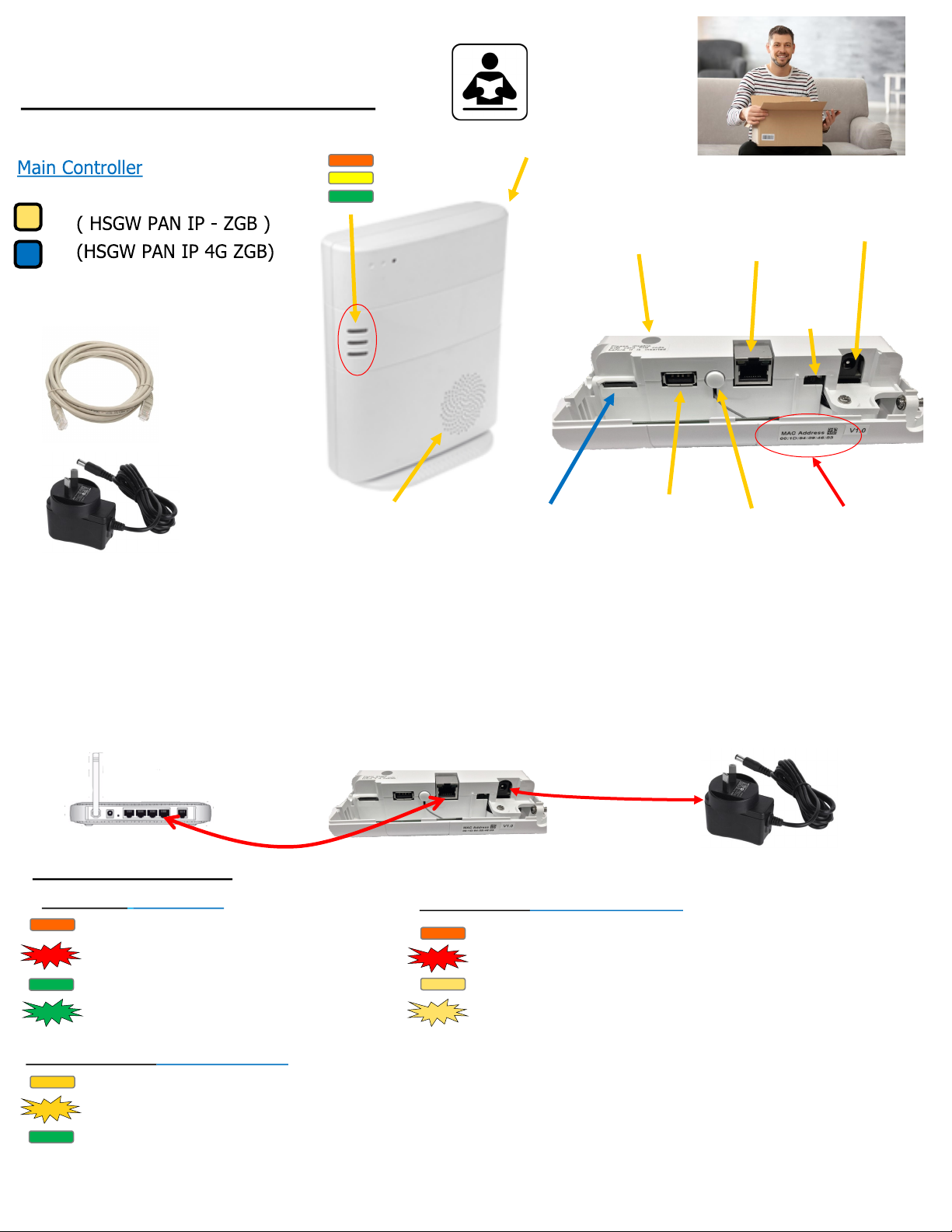
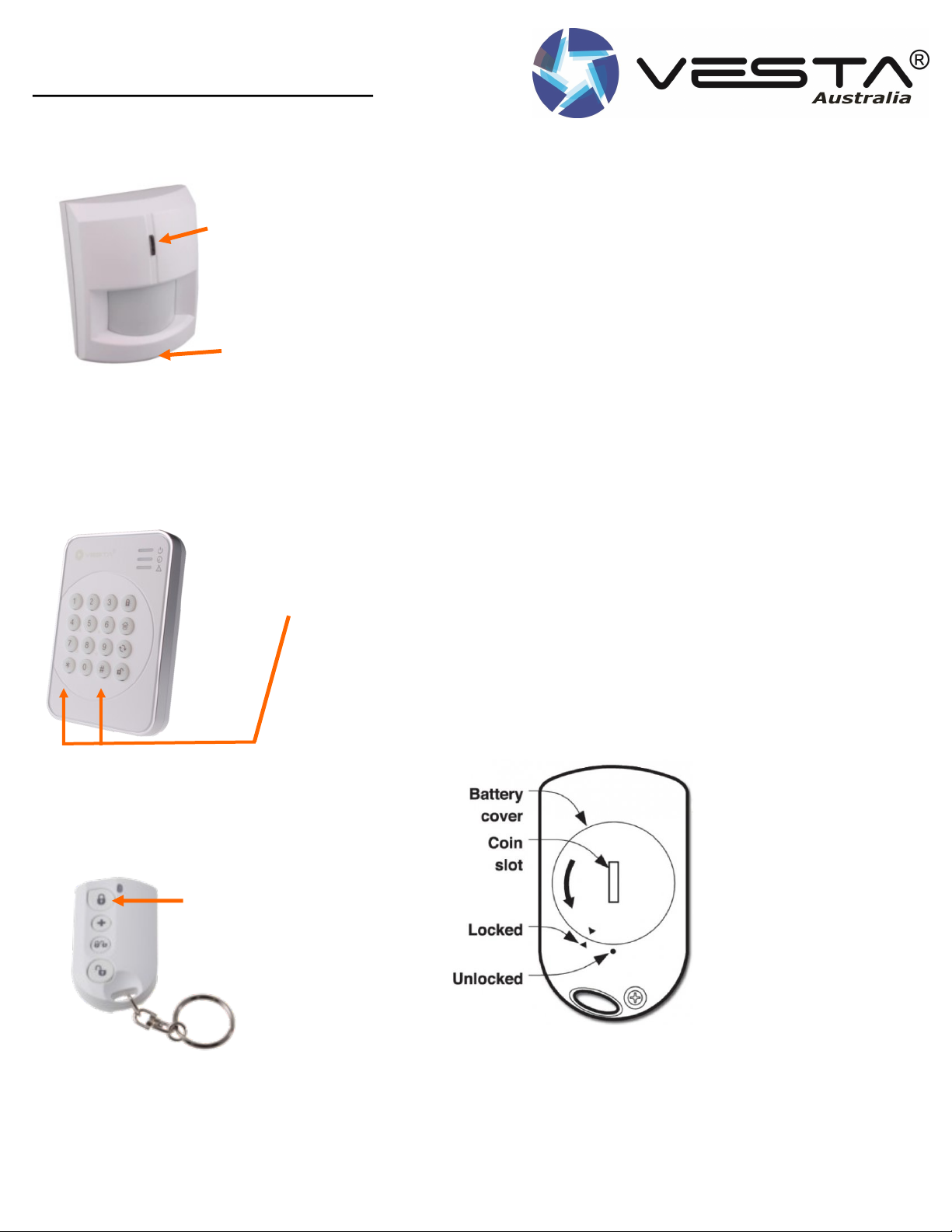
2D Unpack all the parts
Understanding External Siren - BX32-F1
WARNING!
This Siren is very loud, do not trigger the tamper switch
during installation. Wear proper ear protection.
Battery Compartment Tamper switch
Piezo Screamer
Strobe Lights
Mounting
Screw holes x 2
Battery on/off switch
Learn/Test
Button
Siren Tamper
The siren is protected by a tamper switch. Any attempt to open the lid or remove from its mounting surface will result a alarm sounding for a peri-
od of time set by the main Controller. By Default - 3-5 mins.
A tamper message will be sent to the relevant smart phone or monitoring company to notify the tamper triggering has occurred. The Control panel
will also continue to beep until the tamper has been restored.
The Tamper condition can also be bypassed temporarily in the control panel using the Tamper control function. The tamper condition will only be
bypassed for 1 hour until it is restored.
Audio & Visual Status Indication
While arming or disarming the system, the siren uses different audio and visual effect to distinguish various statuses for the user, as listed in the
table below.
• Battery and low battery detection
The Siren is powered by 2 x 1.5 alkaline D batteries.
• If low battery occurs the Siren will transmit a low battery
signal when low battery voltage is detected.
Supervision
• the Siren will transmit a supervisory signal every 30 –50
minutes in normal operation mode. If this signal is not
received , the control panel will indicate that the particular
Siren is Experiencing a fault.
Function overview
Alarm Memory - If an alarm was triggered in your absence and
the alarm was not disarmed , the siren will flash with a notable
sound to let you know an alarm was in distress. It is designed
to get your attention.
When arming or disarming, the siren will sound off with three
chirps with Strobe flash indications.
Arm/Home 1 Beep 3 LED group Flash Once
Disarm 2 Beeps Sequentially Flashes for 1 cycle
Arm ( Low Battery) 3 Beeps 3 LED groups Flashes three times
Disarm ( Low Battery) 3 Beeps Sequentially Flashes three cycles
Arm (Tamper) 5 Beeps 3 LED group Flashes three times
Entry/ Exit Count down No strobe
7
10
10
3A Initial physical setup and connections
Please ensure your Vesta main controller is powered and operational at this point.
VESTA Main Controller
Main home
Router / Internet Connection
Data cable supplied
VESTA Power Plug Pack
Step 1. Remove back cover of the Vesta main controller by unscrewing the four screws top and
bottom.
Step 2. Connect the power plug pack to the 12 volts DC socket on the main Vesta Controller as
illustrated in diagram above.
Step 3. Connect the Data cable Provided in the kit between your Internet router to the Vesta
Main Controller. Be sure your internet router is working properly.
Step 4. Write down the MAC Address of the Vesta Main Controller. You will require this infor-
mation when registering your cloud account.
Step 5 . Using a small screw driver, flick on the Battery backup switch to ON as illustrated in the diagram
below.
SPECIAL NOTE: When the Main controller is powered, you will receive a continues
BEEP. This will occur whilst the back cover is open and the tamper switch is activat-
ed. The BEEP will stop when the back cover is returned and re– screwed.
Now that you have connected the relevant cables to the power and the internet/Router,
the battery backup switch is turned on and the back cover is returned and screwed correctly, you are now
ready to perform the next stage of registration the Vesta alarm system to the VESTA Cloud
Portal.
Your Vesta Main Controller LED Indicator should now be flashing
Mac Address
Battery backup OFF/ON
Switch
OFF - ON
BOTTOM LED 3 (Operation Status)
YELLOW ON = Network Problems
YELLOW Flashing = Disconnected from VESTA Cloud Server
GREEN ON = All SYSTEM NORMAL
8
11
11
3B Initial physical setup and connections
1. Introduction HOME PORTAL
Home Portal™ Sever is a smart home platform, delivering smart home services for end-users to control
home devices and security remotely via PC or smart phones over internet. Home portal™ server enables us-
ers to connect to a home gateway to enjoy convenient services that include security control, alarm event re-
porting, home automation, energy management, and video verification.
Home Portal™ Server provides a good platform to integrate all services and makes life easier for all users.
With Home Portal™ software choices also available on iPhone™, iPad™ and Android mobile devices, you can
directly monitor and control your home status wherever you go!
This User Guide will walk you through the process of Home Portal™ Server registration and operation to pro-
vide a demonstration for the server’s capability. After registering your control panel, you will be able to uti-
lize Home Portal™ Server’s functions that include: System status and setting control, device learning and
management, security event history, image viewing and report setting.
Vesta Home Cloud
Portal Server
Internet Internet
9
12
12
3C Initial App and Vesta Cloud Portal Registration
Accessing Home Portal Server
Home Portal Server can be accessed through web access, through your computer’s internet browser, or application
on a mobile device (smartphone or tablet computer)
For Web Access -
For Australian domain, open your internet browser and enter https://portal.vesta-australia.com/Vesta/
to access the Home Portal Server webpage.
App Access—
The smartphone applications are available for both Android and iOS smartphones and tablets.
Please go to APP Store or Google Play and search Vesta Home 5 AU.
The system requirement for Android device is Android 5.0. The system requirement for iOS device is iOS 7.
NOTE :
The app does not support registration function. For registering your Control Panel in initial setup, please use
the website to access the server.
10
13
13
3D Initial App and Vesta Cloud Portal Registration
Account Registration
The Home Portal Server has a mechanism which only allows registration within the first 15 minutes after a Control
Panel is connected to the server. If the panel does not complete registration within 15 minutes, you should power
down and restart the panel again to reconnect to server and reset the 15 minute timer.
Step 1.
Before registration, connect the panel you wish to register to internet via either IP or GPRS/3G depending on the
models.
Step 2.
With a valid Internet connection, enter https://portal.vesta-australia.com/Vesta/ in your browser to ac-
cess the web page of home portal server and click “New User”.
Step 3.
If you have not connected your panel to internet and power on the panel, follow on screen instruction to do so
Please ensure your Vesta main controller is powered and operational at this point.
VESTA Main Controller
Main home
Router / Internet Connection
Data cable supplied
VESTA Power Plug Pack
Mac Address
Battery backup OFF/ON
Switch
11
14
14
3E Initial App and Vesta Cloud Portal Registration
Account Registration
Step 4. Enter the information required:
Account Info:
Username: Your account username which will be
used to log into the server.
The ID must be unique.
• Password: Enter a password for the user ac-
count
• Confirm Password: Repeat the password as a
confirmation
• E-mail: The email address entered will be used
to receive notification from the server.
• Country Code: Enter your country code.
• Mobile Phone: Your mobile phone number.
• Land Line: Land line telephone number
• Terms and Conditions: Check the box to confirm
you agree with the terms and conditions, click the
link to read the detail.
• NOTE: The terms and conditions listed are only
shown as sample. They are not intended as an
actual agreement between you and VESTA.
• Click “Next” to proceed after entering all info
12
15
15
3F Initial App and Vesta Cloud Portal Registration
Registration Account info
Personal Info: All items under Personal Info are optional.
First Name:
Last Name:
Address: Your physical address
City: The city you live in
State: The state you are in
Zip Code: Your postal zip code
Timezone: Select your timezone
Click “Next” to proceed after entering
all info.
13
16
16
3G Initial App and Vesta Cloud Portal Registration
Registration MAC Address
Registration of the MAC Address of the Main Controller
• MAC/IMEI: Enter the Control Panel’s MAC address,
the MAC address can be found on the label on the
Control Panel.
• Dealer Name: This function allows server to identify
which dealer does the user account belong to. For
testing purpose, please enter “climax” as default.
• Language: Select the display language. Click
“Submit” to proceed after entering all info.
• Step 5. After clicking “Submit”, the server will con-
nect to the Control Panel and complete the registra-
tion process. If you see an error message, it may
indicate one of the following situations.
XMPP Connection Error: The Control Panel is not connected to the server. The Control Panel could be either pow-
ered down, or has internet connection problem. Please check its DC power and network status.
• In case of the control panel being mistaken as malware or virus, please check your firewall setting, make sure
port TCP 5222 is open for XMPP connection and on your firewall exception list.
• Check your router MAC address filter setting and make sure the MAC address of your control panel is authorized
in your router.
• If you are using the dial-up internet connection, please make sure your router supports ADSL PPPOE function.
• Registration Time Expired: The Control Panel did not complete registration within 15 minutes after connecting to
the server for over 15 minutes
• If registration is successful, the webpage will display success message, click OK to confirm
and return to server homepage.
14
17
17
3H Initial App and Vesta Cloud Portal Registration
Operation - LOGGING In
With a valid Internet connection, enter https://portal.vesta-australia.com/Vesta/in your browser to
access the web page of home portal server.
Step 1. Enter your registered account ID and password and click “Connect” to log into your account.
Check “Remember Me” if you want the webpage to remember your log in info for repeat access.
If you have lost your registered password, click “Forgot Password”, enter your registered ID and click “Submit”.
The server will reset your password and create a
new random password, then send the password
to your registered email
15
18
18
3I Initial App and Vesta Cloud Portal Registration
Operation - LOGGING In
Step 2. You will enter the main page of your account
Security
The Security page displays current system mode and security sensors/devices learnt in the Control panel for quick
access.
16
19
19
3J Initial App and Vesta Cloud Portal Registration
Operation - System Area
Control Panel with only 1 area will display all sensors and system mode in the area.
For Control Panel with more than one area, such as HPGW series, select the operating area to display system mode
and sensor for the selected area only:
System Mode: The system mode is indicated by the 3 buttons at top of the webpage. The current system mode
will light up.
17
20
20
3K Initial App and Vesta Cloud Portal Registration
Operation - System Area
System Mode: The system mode is indicated by the 3 buttons at top of the webpage. The current system mode
will light up.
To change system mode:
Step 1. Click on the desired mode button. You will be required to enter one of the Control Panel User PIN Code to
confirm the action. By Default - 1 2 3 4.
Step 2. Enter the User PIN Code, if the PIN Code is correct, for arming action, the Control Panel will begin Exit
Time countdown.
If incorrect PIN Code is entered, the webpage will display error message and arming will be aborted.
If the system has existing fault events when arming, the webpage will display fault message and arming will be
aborted. If you still want to arm the system, repeat the arming action within 30 seconds to Force Arm.
PIN CODE ERROR
OK
18

Other Vesta Security System manuals

Vesta MZ-1 User manual

Vesta

Vesta MZ-1 User manual

Vesta BOGP-3-G2 User manual

Vesta

Vesta BOGP-3-G2 User manual

Popular Security System manuals by other brands

FBII OMNI-400 EU Installation and setup guide

FBII

FBII OMNI-400 EU Installation and setup guide

Satel Versa user manual

Satel

Satel Versa user manual

Essentials EL00160 manual

Essentials

Essentials EL00160 manual

Gemini 932 Series Installation and use manual

Gemini

Gemini 932 Series Installation and use manual

Serene CentralAlert CA-360 user manual

Serene

Serene CentralAlert CA-360 user manual

ADEMCO 4140XMPT2 user manual

ADEMCO

ADEMCO 4140XMPT2 user manual

Ingics iBS04 user guide

Ingics

Ingics iBS04 user guide

Honeywell VISTA-21iP Programming guide

Honeywell

Honeywell VISTA-21iP Programming guide

Safeline SL6+ manual

Safeline

Safeline SL6+ manual

Rafiki Protection Quadnet installation instructions

Rafiki Protection

Rafiki Protection Quadnet installation instructions

Europlex SigNET 200 user guide

Europlex

Europlex SigNET 200 user guide

DEXAPLAN GA 617 -  B DU 11-2007 Operation and safety notes

DEXAPLAN

DEXAPLAN GA 617 - B DU 11-2007 Operation and safety notes

Mircom BL-10B quick start guide

Mircom

Mircom BL-10B quick start guide

Gemini 933MHW user manual

Gemini

Gemini 933MHW user manual

Lorex SHS-2S7LDP series Specifications

Lorex

Lorex SHS-2S7LDP series Specifications

ADEMCO 745x3 installation guide

ADEMCO

ADEMCO 745x3 installation guide

COBHAM SAILOR 3771 installation manual

COBHAM

COBHAM SAILOR 3771 installation manual

Arlec AM720 operating instructions

Arlec

Arlec AM720 operating instructions

manuals.online logo
manuals.online logoBrands
  • About & Mission
  • Contact us
  • Privacy Policy
  • Terms and Conditions

Copyright 2025 Manuals.Online. All Rights Reserved.