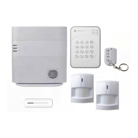
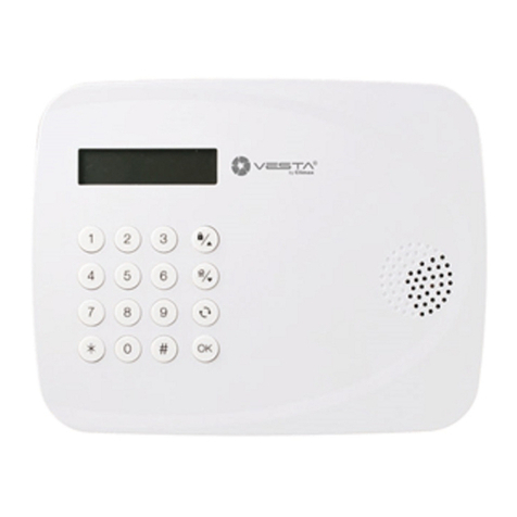
Vesta MZ-1 User manual

Feb-03-2015

Table of Contents
1. INTRODUCTION_____________________________________________________________________ 1
2. APPLICATION OVERVIEW ____________________________________________________________ 2
2.1. IDENTIFYING THE PARTS:_____________________________________________________________ 2
2.2.THE POWER SUPPLY: _______________________________________________________________ 5
2.3. SYSTEM REQUIREMENTS: ____________________________________________________________ 6
3. GETTING STARTED__________________________________________________________________ 7
3.1. SYSTEM DEPLOYMENT ______________________________________________________________ 7
3.2. HARDWARE INSTALLATION FOR MZ-1/8 __________________________________________________ 8
3.3. SOFTWARE INSTALLATION FOR MZ-1/8__________________________________________________ 10
4. CONNECTING TO WEBPAGE_________________________________________________________ 13
5. SYSTEM SETTINGS_________________________________________________________________ 15
5.1. USER__________________________________________________________________________ 15
5.2. REPORT________________________________________________________________________ 17
5.3. PANEL _________________________________________________________________________ 20
5.4.AREA__________________________________________________________________________ 23
5.5. NETWORK ______________________________________________________________________ 26
5.6. GSM__________________________________________________________________________ 28
5.7. UPLOAD________________________________________________________________________ 30
6. DEVICE MANAGEMENT _____________________________________________________________ 31
6.1. LEARNING ______________________________________________________________________ 31
6.2.ADD DEVICE_____________________________________________________________________ 34
6.3. WALK TEST _____________________________________________________________________ 35
6.4. EDIT DEVICE ____________________________________________________________________ 36
6.5. DELETE DEVICE __________________________________________________________________ 41
6.6.TEMPORARY BYPASS DEVICE ________________________________________________________ 41
6.7. IDENTIFY ZIGBEE DEVICE ___________________________________________________________ 41
6.8. REQUEST MEDIA _________________________________________________________________ 42
6.9. POWER SWITCH CONTROL __________________________________________________________ 42
6.10. SIREN LEARNING/CONTROL ________________________________________________________ 42
7. CAPTURED EVENTS________________________________________________________________ 44
8. HISTORY RECORDS ________________________________________________________________ 46
8.1. HISTORY _______________________________________________________________________ 46
8.2. REPORTED EVENT ________________________________________________________________ 47

9. PANEL CONTROL __________________________________________________________________ 48
10. HOME AUTOMATION_______________________________________________________________ 49
11. FIRMWARE_______________________________________________________________________ 53
12. SMS REMOTE COMMAND (MZ-8 ONLY) _______________________________________________ 54
12.1. SMS COMMAND LIST _____________________________________________________________ 55
13. VESTA EZ HOME APPLICATION (MZ-8 ONLY) __________________________________________ 60
13.1. FOR IPHONE ___________________________________________________________________ 60
13.2. FOR ANDROID PHONE_____________________________________________________________ 68
14. REMOTE ACCESS (MZ-8 ONLY)______________________________________________________ 79
15. APPENDIX _______________________________________________________________________ 80
15.1. CONTROL PANEL MODE AND RESPONSE TABLE __________________________________________ 80
15.2. EVENT CODE ___________________________________________________________________ 82

1
1. Introduction
This manual covers the installation, programming, and control of IP based MZ-1 and MZ-8
control panels. Both MZ-1 and MZ-8 supports full range IP reporting capability with webpage for
setting configuration and system control, MZ-8 also has the extra function of reporting through
GSM and/or GPRS.
The advanced IP Security System with fully integrated TCP/IP technology and Ethernet
connectivity is able to take full advantage of new advances in IP Home Security and Home
Automation and multi-path signalling.
Remote control of the panel is achieved by registering the panel in our Home Portal Server.
With Home Portal Server, you can connect to your panel anytime, anywhere in the world
through internet connection either with a computer or a smartphone using our Vesta Home
application. Please refer to our Home Portal User Guide for detail about registering and using
Home Portal Server.
SMS remote programming and command is also available for MZ-8 to configure your panel by
SMS messages. You can also use our Vesta EZ Home smartphone applications to send the
SMS commands easily for basic panel functions.

2
2. Application Overview
2.1. Identifying the parts:
Case A
1. Panel Status LED (Dual Colour - Red & Green)
RED LED ON - System in Away Arm Mode.
RED LED FLASHES - System in Home Arm Mode.
GREEN LED ON - System in Disarm Mode.
GREEN LED FLASHES - System in Learn Mode.
LED OFF - System in Walk Test Mode
2. Alarm & Fault Status LED (Dual Colour - Red & Yellow) (with display priority)
RED LED FLASHES - System is currently alarming.
RED LED ON - Alarm memory in system.
YELLOW LED FLASHES - AC Power failure.
YELLOW LED ON – Other fault condition (not including AC Power Failure ).
LED OFF – System normal.
LED Flashing Sequence:Alarm>Alarm Memory>Panel AC failure>Other Fault
3. Operational Status LED (Yellow)
YELLOW LED ON - Network error

3
LED OFF – Network ok
LED Flashing Sequence: Network ok>Network error
4. Buzzer
5. Ethernet Port
6. Learn / Reset Button
7. SIM Card Module
8. DC Jack
For connecting the DC 9V, 1A
switching power.
9. Battery Switch
10. Tamper Switch
11. Wall Mounting Bracket
Case B
1. Panel Status LED (Dual Colour - Red & Green)
RED LED ON - System in Away Arm Mode.
RED LED FLASHES - System in Home Arm Mode.
GREEN LED ON - System in Disarm Mode.
GREEN LED FLASHES - System in Learn Mode.
LED OFF - System in Walk Test Mode
2. Alarm & Fault Status LED (Dual Colour - Red & Yellow) (with display priority)
RED LED FLASHES - System is currently alarming.
RED LED ON - Alarm memory in system.
YELLOW LED FLASHES - AC Power failure.
YELLOW LED ON – Other fault condition (not including AC Power Failure ).
LED OFF – System normal.

4
LED Flashing Sequence:Alarm>Alarm Memory>Panel AC failure>Other Fault
3. Operational Status LED (Dual Colour - Yellow & Red) (with display priority)
YELLOW LED ON - Network error
LED OFF – Network ok
LED Flashing Sequence: Network ok>Network error
4. Standing Base
5. Internal Buzzer
6. Ethernet Port
7. Learn/Reset Button
8. SIM Card Base
9. DC Jack
For connecting AC adaptor.
10. Battery Switch
Case C
1. Panel Status LED (Dual Colour - Red & Green)
RED LED ON - System in Away Arm Mode.
RED LED FLASHES - System in Home Arm Mode.
GREEN LED ON - System in Disarm Mode.
GREEN LED FLASHES - System in Learn Mode.
LED OFF - System in Walk Test Mode
2. Alarm & Fault Status LED (Dual Colour - Red & Yellow) (with display priority)
RED LED FLASHES - System is currently alarming.
RED LED ON - Alarm memory in system.
YELLOW LED FLASHES - AC Power failure.

5
YELLOW LED ON – Other fault condition (not including AC Power Failure ).
LED OFF – System normal.
LED Flashing Sequence:Alarm>Alarm Memory>Panel AC failure>Other Fault
3. Operational Status LED (Dual Colour - Yellow & Red) (with display priority)
YELLOW LED ON - Network error
LED OFF – Network ok
LED Flashing Sequence: Network ok>Network error
4. Ethernet Port
5. Learn/Reset Button
6. SIM Card Base
7. DC Jack
For connecting AC adaptor.
8. Battery Switch
2.2. The Power Supply:
An AC power adapter is required to connect to a wall outlet. Be sure only to use an adapter with
the appropriate AC voltage rating to prevent component damage. Depending on the Control
Panel, a DC 9V or 12V 1A switching power output adaptor is provided to power the Control
Panel.
Rechargeable Battery
In addition to the adapter, there is a rechargeable battery inside the Control Panel, which
serves as a back up in case of a power failure.
During normal operation, the AC power adapter is used to supply power to the Control
Panel and at the same time recharge the battery. It takes approximately 72 hours to fully
charge the battery.
<
<N
NO
OT
TE
E>
>
If the AC power is missing and the battery is near exhaustion, a low battery message
will be displayed and the internal siren will be disabled to conserve power.

6
2.3. System Requirements:
The system requires a TCP/IP network environment for MZ-1/8 IP Panel to be included in your
network.
To install the CD Wizard, your computer must have:
Microsoft Windows 98, ME, NT4.0, 2000, XP, Vista, 7 or 8 operating system.
Microsoft Internet Explorer 5.x, or later and Mozilla Firefox 1.0 compatible.
CD-ROM drive
CPU: Intel Pentium II 266MHz or above
Memory: 32MB (64MB recommended)
VGA resolution: 800x600 or above

7
3. Getting Started
Read this section of the manual to learn how to set up your MZ-1/8 Panel and program System
Settings over the Web page.
3.1. System Deployment
The Control Panel is designed to be wall mounted, follow guidelines below when planning
installation location:
The Control Panel requires Ethernet connection; depending on the model, a SIM card may
be required.
The Control Panel should be installed at a location that is hidden from outside view.
Avoid mounting the Control Panel near large metal objects which may affect wireless radio
strength
The Control Panel should be protected by sensors so that no intruder can reach the Control
Panel without activating first activating sensor.
When using ZigBee routers to improve ZigBee network coverage, remember to use only
ZigBee Router with backup batteries for security sensors. If you use a Router without
backup battery for security sensors, the Router will be powered down in case of AC failure,
and you security sensors will lose connection with the ZigBee network.
Home Automation devices (Power Switches…etc) do not have this limit and can be used
with any Router.

8
3.2. Hardware Installation for MZ-1/8
Depending on your Control Panel’s casing, choose either wall mounting or desk mounting and
follow instruction below.
Wall Mounting (Case A)
The panel has 4 mounting holes on the back and should be hooked onto the hooks on the
bracket when installed. (Figure 1)
Figure 1
Step 2. Loosen the screw at bottom of panel and remove the compartment cover (Figure 2).
Step 3. Connect the Ethernet cable to the panel. (Figure 3)
For MZ-8, insert a SIM card into the SIM card base. Please make sure the SIM card
PIN Code is disabled before inserting the SIM card.
Step 4. Connect the DC9V 1A adaptor to the panel,
Step 5. Slide Battery Switch to ON position.
Figure2 Figure3
Step 6 Replace the compartment cover and secure with screw. Wire the AC adaptor and
Ethernet cable according to the figure shown through the hole on the cover and the
side. (Figure 4)

9
Figure 4
Step 7. Use the holes on the Mounting Bracket as templates to mark locations on the wall for
wall mounting (Figure 5), insert wall plugs on marked location if fixing into plaster or
brick. (Figure 6) Screw the Wall Mounting Bracket onto the wall. (Figure 7)
Figure5 Figure6 Figure7
Step 8. Hook the Control Panel onto the Mounting Bracket and press downward to secure.
(Figure 8)
Figure 8
Step 9. Plug the adaptor into power socket. Hardware installation for the Control Panel is now
complete; the Panel Status Green LED will turn ON.
Desk Mounting (Case B & Case C)
Step 1. Connect the Ethernet cable and Power adaptor to the Control Panel. For MZ-8, insert
a SIM Card into SIM Card base.
Step 2. Rotate the standing base sideway.
Step 3. Plug the adaptor into power socket. Hardware installation for the Control Panel is now
complete; the Panel Status Green LED will turn ON

10
3.3. Software Installation for MZ-1/8
※THIS INSTALLATION IS ONLY REQUIRED FOR FIRST TIME USER ※
THE “FINDER” SOFTWARE
In order to identify and locate your Control Panel in the Local Area Network, special “Finder”
software is provided to help you connect to Control Panel for programming and control. To install
the “Finder” software.
Step 1. Insert the supplied CD-ROM into your CD-ROM drive
Step 2. Find the Finder software in the CD-ROM
Step 3. Double click on the Finder to initiate the installation.
Step 5. Click “Change” to select the file folder, if no change is required; click “Next” to get
ready for the installation process.
Step 6. Click “Next” to begin the Installation. Once the installation is completed, click “Finish”
to confirm.
Step 7. Anew icon will be displayed on your desktop.
Step 8. Double click on the “Finder.exe” to start the installation. The following screen will be
displayed:

11
Step 9. Click on “Search”, It will start searching for recognized IP address within the Local
Area Network.
Step 10. You will be able to locate the current Control Panel IP address among the list.
Displayed with MAC Address and Product version.
Step 11. Once the Control Panel is identified, select the panel and click on “Open Web Page”
to link to the IP Security System Web page.
Step 12. Software installation is now completed.

12
CONFIGURE PANEL NETWORKSETTING
This function is only required if you want to configure network setting manually.
Step 1. Select the panel, then click on Configure Setting, the following window will display:
Step 2. Enter the network setting and a user name and password for setting configuration.
(Default) User Name: admin
(Default) Password: admin1234
Step 3. Select either DHCP or Static for the LAN Type. If Static is selected, you can proceed
to enter rest of the network information manually. If “DHCP” is selected, you will not be
able edit the network information.
Step 4. After you enter a new setting, click OK to confirm. If the username and password are
correct, a window will display: Status: Configure success!!

13
4. Connecting to Webpage
Step 1. Select MZ-1/8 in the Finder software and click on “Open Webpage” to connect to
MZ-1/8 webpage.
Alternatively, enter MZ-1/8 IP address displayed in Finder into your browser’s address
section and click “GO”.
Step 2. Enter the User name & Password.
Step 3. Enter the User name & Password and then press “OK”.
User Name: admin Password: admin1234

14
Step 4. You will enter the Control Panel webpage, the current Control Panel information will be
displayed.

15
5. SYSTEM SETTINGS
5.1. User
User Code
The User Codes are used for users to acess the alarm system. A total of 10 4-digit User
Codes can be stored in MZ-1/8. Each individual User can be given a name for easy
recognition when viewing system events.
User PIN code #1 is activated with “1234” as factory default. User PIN code #2~#10 are
deactivated by factory default
<
<N
NO
OT
TE
E>
>
When entering User PIN Codes with a Remote Keypad, if the wrong PIN Codes were
entered 5 times in 10 minutes, the Control Panel will prohibit further User PIN Code
entry for 15 minutes. All User PIN Codes entered during the 15 minute period will result
in error for the Remote Keypad.
Guard Code
The Guard Code is designed for security personnel to arm/disarm the system. When this
code is used for accessing the system, the Control Panel will record the event separately
from the User Codes.
The Guard Code consists of 4 digits and is not activated as default by the factory.
Master Code
This function is currently disabled
Factory default: 1111.

16
Temporary Code
The Temporary Code is used to access the system for a temporary user and is valid for
only one arming and disarming action. Afterwards, the Temporary Code is automatically
erased and needs to be reset for a new Temporary user.
The Temporary Code consists of 4 digits and is not activated as default by the factory.
Duress Code
The Duress Code is used to access the system in duress situation. When this code is used
for accessing the system, the Control Panel will report a secret alarm message without
sounding the siren to the Central Monitoring Station to indicate of a “Duress Situation in
Progress”.
The Duress Code consists of 4 digits and is not activated by factory default.
Installer Code
The Installer Code is used for the installer to access the Control Panel via SMS remote
command.
Factory default: 7982.
Latch Option
Whe the option is selected, the Control Panel will report all arming/disarming action by this
user.
Latch.
When the the Latch option box is ticked, the Latch option is turned ON.
To edit the Codes on Web Page:
Step 1. Key in your preferred 4-digit code
Step 2. Enter a name for the code (optional)
Step 2. Choose to tick On / Off the Latch Option box.
Step 3. Press “Submit” to confirm the new uploaded details.

17
5.2. Report
This page is for you to enter the report destination setting. MZ-1/8 can store up to 8 report
destinations.
Reporting Type:
MZ-1/8 supports the following reporting types:
IP/GPRS reporting in CID format:
Reporting destination format: ip://Account@Server IP:Port/CID
ip:// 6543 @59.124.123.23 :8765 /CID
Reporting
type Account
(4-8 digits) Server IP
address Port
number Reporting
Format
IP/GPRS reporting in SIA format:
Reporting destination format: ip://Account@Server IP:Port/SIA
ip:// 6543 @59.124.123.23 :8765 /SIA
Reporting
type Account
(4-8 digits) Server IP
address Port
number Reporting
Format
IP/GPRS reporting in CSV format:
Reporting destination format: ip://Account@Server IP:Port/CSV
ip:// 6543 @59.124.123.23 :8765 /CSV
Reporting
type Account
(4-8 digits) Server IP
address Port
number Reporting
Format
This manual suits for next models
1
Table of contents
Other Vesta Security System manuals