Vestamatic LL-ME-BAT/I-24/0,6 Nm RB IO-AIR User manual

Subject to modifications.© Vestamatic GmbH
Art.-Nr.: 1253 001 GB 2218 A05 • Vestamatic GmbH • Dohrweg 27 • D-41066 Mönchengladbach • www.vestamatic.com
1/8
G
PRO ·LL-ME-BAT/I-24/0,6 Nm RB IO-AIR
LL-ME-BAT/I-24/0,6 Nm
RB IO-AIR
Lovoline
IO-AIR Installation and Operating Instructions
LL-ME-BAT/I-24/0,6 Nm RB IO-AIR Art.-no.: 01010204
Lovoline battery-motor motor for controlling
roller blinds and screens.
G
PRO
1253 001 GB 2218 A05
1. Safety precautions (safety measures)
2. Short description (Identification of products)
3. Intended use
4. Technical data
5. Installation, assembly, dissasembly
6. Startup and usage
7. Settings in radio operation IO-AIR
8. Warranty
9. Declaration of conformity
10. Maintenance
11. Disposal of waste
12. Service / Contact
CONTENTS
3.
Intended use
The type of motor listed in this manual is a battery-powered motor, that is
specifically for precise control of sun protection systems.
The motor cannot be used in potentially explosive area. This type of motor
is designed for using in a single sunshade system.
1. Safety precautions
WARNING!
Important safety information.
– Contact a professional electrician for installation.
– Check the motor for signs of mechanical damage after un-
packing. If you notice any shipping damage, do not start up
the motor and notify your supplier immediately.
– The motor should only be used for the purpose specified by
the manufacturer (refer to the operating instructions). Any
changes or modifications thereof are not permissible and will
result in loss of all warranty claims.
– If the motor or the connected sunshade cannot be operated
without presenting a hazard, it must be switched off.
– When performing work on the windows, motor or connected
shades, protect them against unauthorised or unintentional
operation.
– Technical data can be found on the type label of the motor.
Ä
WARNING!
Important safety information.
Follow these instructions to ensure the safety of persons.
The instructions must be stored.
– Children are not allowed, to play with fixed controls. Keep
remotes away from children.
– The installation has to be checked frequently for imbalance
or of signs of wear.
Ä
WARNING!
Important safety information.
Follow all installation instructions, as incorrect installation
can lead to serious injuries.
– The installer must adhere to the standards and regulations
of the installation country and inform the customer about the
use and maintenance.
– Stationary mounted control units have to be fixed in sight.
– The rated torque and the rated operating time must be in
compliance with the attributes of the driven parts.
Ä
2. Short description
Lovoline motor with integrated battery and radio-technology
For accurate control of roller blinds/screens
User-friendly operation via IO-AIR radio transmitter
Slow motor speed at start and stop
Parallel control via broadcast-command
Adjustable motor speed in different steps
Intermediate position storage
Obstacle detection / Brake functionality
4. Technical data
Article LL-ME-BAT/I-24/0,6 Nm RB IO-AIR
Art.-no.: 01010204
Power supply: DC 5V-USB
Battery-inside: Li-Ion battery 181)
Output current (charger): Amin. 1
Chargetime: hours up to 6
Rated power (nominal): W 3
Torque (nominal): Ncm2) 60
Draw weight: kg 1.3
Maximum on time: Min.
10 min. at +25 °C (77 °F) ambient temp.
Output speed: rpm 15–50
Radio frequency: MHz 868
Radiated power: mW 12.5
Operating temperature: °C 0 °C (32 °F) to +60 °C (140 °F)
Protection degree: IP 20
LED: Colour: green/blue
Length L1: mm 259
Conformity:
p
1)
The battery can not be replaced.
2)
At a motor speed of 30 rpm.

Subject to modifications.© Vestamatic GmbH
Art.-Nr.: 1253 001 GB 2218 A05 • Vestamatic GmbH • Dohrweg 27 • D-41066 Mönchengladbach • www.vestamatic.com
2/8
G
PRO ∙LL-ME-BAT/I-24/0,6 Nm RB IO-AIR
5. Installation, assembly, disassembly
ATTENTION!
Tubular motor might be switched off before reaching the
limit position:
Extraordinary large increases of load (anti-block-function) –
obstacles, sunshade system keeps jamming, tubular motor is
overloaded.
Remedy action:
– Removing the obstacle.
– Check the mechanical parts of the sunshade system.
– Use the correct tubular motor according the spezification of
the sunshade system.
ÄThe motor is designed for installation in various tubular shafts. The suitable
adapter sets can be found in the accessory program (not included in the
scope of delivery).
A. Adapter sets (roller blinds/screens):
A1 = Drive
A2 = Crown
A3 = Bracket
To ensure proper installation, please observe the assembly description.
The motor has a terminal connection micro-USB. You will find suitable
connection cables in the accessory program (not included in the scope of
delivery).
Assembly adapter sets
NOTE:
When mounting the motor in the tubular system, make sure that the
PROG. button and the micro USB connector remain accessible.
i
5.1 Product description
Description:
1 PROG. button
2 Micro-USB connector
3 Blue LED
4 Green LED

Subject to modifications.© Vestamatic GmbH
Art.-Nr.: 1253 001 GB 2218 A05 • Vestamatic GmbH • Dohrweg 27 • D-41066 Mönchengladbach • www.vestamatic.com
3/8
G
PRO ·LL-ME-BAT/I-24/0,6 Nm RB IO-AIR
6. Startup and usage
1. The motor is in transport mode and must be woken up before first use.
2. To wake up the motor, connect a charger or a suitable power bank to
the Micro USB socket.
5V DC, min. 1 A
3. After plugging in the charger, the green and blue LEDs light up briefly.
The motor is now active.
NOTE:
Before first use, the motor should be fully charged.
i
Charging the motor
To charge the motor, a standardized charger or a power bank with at least
1 ampere output current can be used.
Charging the motor is necessary if it shows one of the listed behaviors.
– Take a micro-USB charger or a power bank and plug the cable into the
micro-USB socket on the motor head.
– Plug the charger into the socket. A power bank may need to be activated.
– After approx. 1 sec the blue LED on the motor head is constantly lit. The
charging process is thus initiated. After about 1 minute the motor can
be moved again. The entire charging process can take up to 6 hours.
– Charging is completed when the blue LED on the motor head goes out
and the green LED lights up permanently. The micro-USB connector
can then be removed from the motor head.
Motor behavior with low battery
If the battery of the motor is running low, the motor will display the following
behaviors for ensuing movements.
Blue LED flashes
The blue LED on the motor head flashes twice every 30 seconds.
Reduced motor speed
The motor only runs at low speed to signal that it needs to be charged.
Motor remains at the upper limit position
When the battery reaches a critical level, the motor automatically
goes into sleep mode to prevent damage to the battery.
Within this process, the motor drives to the upper limit position one
last time. Further commands are only executed after a charger has
been connected.
NOTE:
When charging with a power bank, it will automatically switch off
after the charging process has ended, as a result the green LED
on the motor head will go out shortly after.
i
LED-Feedback on motor head
Blue LED constantly lit
The motor is charging.
Blue LED flashes
An error occurred while loading.
Green LED constantly lit
The charging process is completed.
Green LED flashes
The motor is in programming mode.
No reaction of green or blue LED
If none of the LEDs provide feedback after pressing the programming
button on the motor head, the motor is in transport mode or has shut
down due to critical battery voltage.

Subject to modifications.© Vestamatic GmbH
Art.-Nr.: 1253 001 GB 2218 A05 • Vestamatic GmbH • Dohrweg 27 • D-41066 Mönchengladbach • www.vestamatic.com
4/8
G
PRO ·LL-ME-BAT/I-24/0,6 Nm RB IO-AIR
7. Settings/Functions of the motors
in radio operation IO-AIR
The motor can be controlled with multiple IO-AIR radio transmitters.
Subsequently, these are described depending on the radio transmitter type.
A maximum of 16 transmitters per motor can be programmed.
Description of radio remote control IO-AIR Transmitter
A. LED indication of selected channel of the
transmitter.
To change channel:
Briefly press one of the two channel selection
buttons
+
or . The LEDs show the current
selected channel. Use the button
+
or to
select the channel. The selection is saved im-
mediately.
PROG. button
at the back side
Function + Programming Transmitter
Radio Remote Control IO-AIR
B. IO-AIR Transmitter 5C:
Switching from AUTO to MANUAL mode
(receiver-dependent).
Press and hold the button and then press
the
+
button for 5 seconds until the operat-
ing mode switches. The LEDs AUTO or MAN
and the channels will light up briefly.
IO-AIR Transmitter 10C:
Left LED indication channel 1–5
Right LED indication channel 6–10
C. Manual control buttons.
Channel 1– 10 = Motor / Shade / Lighting
Button ON/UP = Q
Button STOP
Button OFF/DOWN = q
B.
A.
C.
PROG. button
LED
Description of radio wall transmitter IO-AIR Switch

Subject to modifications.© Vestamatic GmbH
Art.-Nr.: 1253 001 GB 2218 A05 • Vestamatic GmbH • Dohrweg 27 • D-41066 Mönchengladbach • www.vestamatic.com
5/8
G
PRO ·LL-ME-BAT/I-24/0,6 Nm RB IO-AIR
– Briefly press the PROG. button at the motor-
head. Programming mode is now active for
60 sec. while the green LED flashes continuously.
– Press PROG. button at the back side of the
remote control.
– LED starts flashing.
– Press ON/UP button of the channel for pro-
gramming shortly.
– The motor will give a feedback (two short
UP/DOWN movements) to confirm that the ins-
tallation procedure has ended.
The flashing of the LED on the back side stops
after 1 second.
– To drive the motor in UP or DOWN direction,
please press the respective button. Motor moves
with a delay, since no final positions are set.
Programming for initial operation respectively after RESET
– Briefly press the PROG. button at the motor-
head. Programming mode is now active for
60 sec. while the green LED flashes continu-
ously.
– Press PROG. button at the back side of the
remote control.
– LEDs on the front side of the remote control
start flashing.
– Press and release the STOP button short-
ly. The motor will give a feedback (two short
UP/DOWN movements). Programming was
successful. The flashing of the LEDs on the
front side of the remote control stops after
about 1 sec., then the motor can be driven.
– To drive the motor in UP or DOWN direction,
pleasepress the respectivebutton. Motor moves
with a delay, since no final positions are set.
PROG. button
at the back side
Radio remote control IO-AIR Transmitter
Radio wall transmitter IO-AIR Switch
PROG. button
LED
– Hold down the button or to check the motor turning direction.
– When the motor reacts in opposite direction (when motor goes down
when you press UP and vice-versa), you need to change the motor
direction. Motor direction can only be changed during installation phase,
when no limit positions are set.
– Shortly press the following combination of buttons (within 10 seconds):
– The motor will give a short feedback if the process is finished.
Changing motor turning direction
Setting electronic limit position
ATTENTION!
The motor starts to move with a short delay time during instal-
lation phase, when no limit positions are set.
Ä– Hold down the button to move the motor in the requested lower
limit position.
For precise moving of the motor briefly press the button , press
again and hold.
– Press the following button sequence (within 10 seconds): 5 × short .
– The motor will give a short feedback if the process is finished.
Setting the lower limit position
– Hold down the button to move the motor in the requested upper
limit position.
For precise moving of the motor briefly press the button , press again
and hold.
– Press the following button sequence (within 10 seconds): 5 × short .
– The motor will give a short feedback if the process is finished.
Setting the upper limit position
The installation procedure is finished and the limit position settings are
saved.
– Press the button or = self-locking.
– Press the opposite button or STOP button of the radio remote control
to stop the drive.
Precise controlling with set limit positions
– Hold down the button or .
The motor now moves at a slower speed and can thus be precisely
steered to the desired position.
– After releasing the directional button, the motor is immediately stopped.
NOTE:
The function is only available when the limit positions have been
set completely.
i

Subject to modifications.© Vestamatic GmbH
Art.-Nr.: 1253 001 GB 2218 A05 • Vestamatic GmbH • Dohrweg 27 • D-41066 Mönchengladbach • www.vestamatic.com
6/8
G
PRO ·LL-ME-BAT/I-24/0,6 Nm RB IO-AIR
Adjusting already set limit positions of the motor
Change the electronic limit positions
PROG. button
at the back side
IMPORTANT!
The motor starts to move with a short delay time during instal-
lation phase, when no limit positions are set.
ÄStart with lower limit position setting
– Hold down the button to move the motor in the requested lower limit
position.
For precise moving of the motor briefly press the button , press again
and hold.
– Press the following button sequence (within 10 seconds): 5 × short .
– The motor will give a short feedback if the process is finished.
– Hold down the button to move the motor in the requested upper
limit position.
For precise moving of the motor briefly press the button , press again
and hold.
– Press the following button sequence (within 10 seconds): 5 × short
– The motor will give a short feedback if the process is finished.
– The installation procedure is finished and the limit position settings are
saved.
– The blinking of the LEDs on the front side of the remote control disap-
pears after about 10 seconds, then the motor can be driven.
NOTE:
Adjusting only with
radio remote control,
not available with wall-
mounted transmitter.
Press the PROG. button twice
(see figure left) on the back side of
the radio remote control until the
following LEDs flash.
i
– The intermediate position can be saved only after
the lower and upper limit positions have been
saved finally.
– Briefly press the UP or DOWN button = self-locking.
Press the opposite button or STOP button to stop
drive.
– When the desired position is reached, press the
following button sequence (within 10 seconds):
5 × shortly the STOP button.
– The motor will give a feedback (short UP/DOWN
movement) to confirm that the installation proce-
dure has ended.
Save intermediate position
NOTE:
Save intermediate position (only with radio remote control, not
available with wall-mounted transmitter).
i– Once the intermediate position is stored, the motor reacts according to
button stroke length.
Briefly press the UP or DOWN button = Intermediate position.
Press the button UP or DOWN twice = run over the intermediate
position.
– The stored intermediate position can be changed/overwritten at any
time.
Deleting the intermediate position:
– Driving the motor in the lower limit position.
– When the limited position is reached, press the following button sequence
(within 10 seconds): 5 × briefly the STOP button.
– The motor will give a short feedback if the process is finished.
By means of the programmed radio remote control
– Press the PROG. button (see
figure left) on the back side of
the radio remote control several
times until the following LEDs
flash. Then press the STOP
button.
– The motor briefly performs
ON/UP and OFF/DOWN com-
mands. The blinking of the LEDs
on the front side of the remote
control disappears after about
1 seconds, then the motor can
be driven.
After the motor RESET, the programming mode is automatically active
for 60 seconds. The motor starts to move with a short delay time during
installation phase, when no limit positions are set.
Motor – RESET
PROG. button
at the back side
By means of the PROG. button at the motorhead
– Press and hold the PROG. button (see figure right) on the motorhead
for about 10 seconds until the green LED is constantly lit.
Now release the PROG. button again.
– The motor acknowledges the RESET by a short flashing of the blue
LED.
NOTE:
If a RESET is carried out using the PROG. button on the motor
head, the programming mode does not activate automatically.
i
Delete the limit position settings of the motor and
all programmed radio transmitter
1 PROG. button
2 Blue LED
3 Green LED

Subject to modifications.© Vestamatic GmbH
Art.-Nr.: 1253 001 GB 2218 A05 • Vestamatic GmbH • Dohrweg 27 • D-41066 Mönchengladbach • www.vestamatic.com
7/8
G
PRO ·LL-ME-BAT/I-24/0,6 Nm RB IO-AIR
Programming of additional remote controls
Briefly press the PROG. button at the motorhead. Programming mode
is now active for 60 sec. while the green LED flashes continuously.
Radio remote control IO-AIR Transmitter – as described above.
Radio wall transmitter IO-AIR Switch – as described above.
Successful programming:
The motor briefly performs two ON/UP and OFF/DOWN commands.
Programming of additional radio transmitter by means of a
programmed radio transmitter.
– Select the corresponding channel with the programmed radio trans-
mitter.
– Press the PROG. and then the STOP button (radio remote control)
resp. ON/UP button (wall-mounted radio transmitter).
– The motor is now for 10 sec. in programming mode. The motor per-
forms a short ON/OFF and UP/DOWN movement command.
Programming the radio remote control IO-AIR transmitter:
Press the PROG. and then the STOP button.
Programming the radio wall transmitter IO-AIR Switch:
Press the PROG. and then the ON/UP button.
Successful programming:
The motor briefly performs two ON/UP and OFF/DOWN commands.
Option 1 Option 2
By means of the programmed radio remote control
– Press the PROG. button (see
figure left) on the back side of
the radio remote control several
times until the following LEDs
flash (Fig. B). Then press the
STOP button.
– The motor briefly performs
ON/UP and OFF/DOWN com-
mands. Delete mode will now
be enabled for 10 seconds.
PROG. button
at the back side
Deleting a programmed radio remote control
By means of the programmed radio wall transmitter
– Press the PROG. button on the
back side of the radio wall trans-
mitter once, the red LED flashes.
– Briefly press the OFF/DOWN
button. The deletion process is
terminated after approx. 10 sec.
– The motor briefly performs
ON/UP and OFF/DOWN com-
mands.
PROG. button
LED
Deleting a radio remote control IO-AIR Transmitter
– Within10seconds,presstheSTOP button ontheradioremotecontroltobe
deleted. When you release the button, the motor briefly performs two
ON/UP and OFF/DOWN move commands.
– Cancellation is now effective.
Setting the motor speed
NOTE:
If an already set motor speed is selected, the motor does not
execute ON / OFF and OFF / DOWN commands for confirmation.
i
– Press the PROG. button (see
figure left) on the back side of
the radio remote control several
times until the following LEDs
flash.
– For the desired motor speed,
press one of the following but-
tons:
50 rpm = UP button Q
30 rpm = STOP button ·
15 rpm = DOWN button q
– The motor briefly performs one
ON/UP and OFF/DOWN mo-
vement.
– The setting of the motor speed
is completed.
PROG. button
at the back side

Subject to modifications.© Vestamatic GmbH
Art.-Nr.: 1253 001 GB 2218 A05 • Vestamatic GmbH • Dohrweg 27 • D-41066 Mönchengladbach • www.vestamatic.com
8/8
G
PRO ∙LL-ME-BAT/I-24/0,6 Nm RB IO-AIR
These products comply with the essential requirements. These
products are conform to the basic requirements of the European
Radio Equipment Directive 2014/53EU. The Declaration of Con-
formity concerning these products are available on our website:
www.vestamatic.com.
9. Declaration of conformity
p
The disposal of electrical equipment and batteries in household
waste is strictly forbidden.
The symbol (dustbin crossed out, in line with WEEE Appendix IV)
indicates separate collection of electrical and electronic products in
EU countries. Do not dispose of the device or battery in your house-
hold waste. Ask your town or local council about the return and
collection systems available in your area to dispose of this product.
É
11. Disposal of waste
8. Warranty
Principally, the General Terms and Conditions of the manufacturer, Vestamatic
GmbH apply. The terms and conditions are part of the sales documents
and handed over to the operator upon delivery. Liability claims for personal
or material damages are excluded when they can be attributed to one or
more of the following causes:
– Unintended use of the product.
– Opening of the product by the customer.
– Improper installation, commissioning, or operation of the product.
– Non-compliance with the technical specifications.
– Non-observance of the safety provisions and instructions of the Oper-
ating Instructions.
– Operation of the product with improperly installed connections, defective
safety devices or improperly installed safeguards.
– Modifications to the product.
10. Maintenance
The motor is maintenance free.
12. Service/Contact
Vestamatic GmbH
Dohrweg 27
D-41066 Mönchengladbach / Germany
Tel.: +49 2161/29 408-0
Table of contents
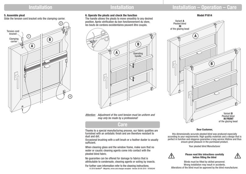
Popular Window Blind manuals by other brands

Style selections
Style selections 70807 installation guide

Renson
Renson Fixscreen Minimal User manual & warranty conditions

debel
debel Touch quick start guide

rollease acmeda
rollease acmeda S100 EXTREME SYSTEM installation manual

Franc Gardiner
Franc Gardiner smartroll 32-1 Assembly instructions

HunterDouglas
HunterDouglas 2" Horizontal Aluminum Blinds Installation operation care