Vestil AIR-THL User manual

VESTIL MANUFACTURING CORP.
2999 North Wayne Street, P.O. Box 507, Angola, IN 46703
Telephone: (260) 665-7586 -or- Toll Free (800) 348-0868
Web: www.vestilmfg.com e-mail: info@vestil.com
AIR-THL
PNEUMATIC LOAD TILTER
Receiving Instructions
After delivery, remove the packaging from the product. Inspect the product closely to determine
whether it sustained damage during transport. If damage is discovered, record a complete
description of it on the bill of lading. If the product is undamaged, discard the packaging.
Notes: 1) The manufacturer continually develops all equipment and accessories. It reserves the right
to make changes to the models from time to time. No claims may be made based on the
information and illustrations contained in this manual. 2) The end-user is solely responsible for
confirming that product design, use, and maintenance comply with laws, regulations, codes, and
mandatory standards applied where the product is used.
Technical Service & Replacement Parts
For answers to questions not addressed in these instructions and to order replacement parts, labels,
and accessories, call our Technical Service and Parts Department at (260) 665-7586. The
Department can also be contacted online at https://www.vestil.com/page-parts-request.php.
Electronic Copies of Instruction Manuals
Additional copies of this instruction manual may be downloaded from
https://www.vestil.com/page-manuals.php.

REV I | 8/6/19
2
1. Introduction .................................................................................................................. 3
1.1 Using This Manual .................................................................................................... 3
2. Description of Equipment .......................................................................................... 4
2.1 Specications ............................................................................................................4
3. Safety ............................................................................................................................. 5
3.1 User/Owner Responsibility ...................................................................................... 5
3.2 Safety Guidelines ...................................................................................................... 5
3.3 Material Safety .......................................................................................................... 6
3.4 Energy Isolation ........................................................................................................ 6
4. Installation .................................................................................................................... 8
4.1 Pre-Shipment Planning ............................................................................................ 8
4.2 Inspection of Shipment ............................................................................................. 8
4.3 Installation Guidelines ..............................................................................................8
4.4 RetrotPackages ......................................................................................................9
5. Sequence of Operation .............................................................................................10
5.1 Operating Sequence ................................................................................................10
5.2 Foot Pedal Operation .............................................................................................. 10
5.3 Hand Valve Operation .............................................................................................10
6. Maintenance ...............................................................................................................11
6.1 Considerations ........................................................................................................ 11
6.2 Maintenance Schedule ............................................................................................ 11
6.3 Airbag Replacement ...............................................................................................12
7. Caster Retrot Package ............................................................................................13
7.1 Installation .............................................................................................................. 13
7.2 Operation ................................................................................................................ 14
8. Safety Ratchet Retrot Kit ........................................................................................15
8.1 Installation .............................................................................................................. 15
9. Warranty ......................................................................................................................19
Contents

REV I | 8/6/19
3
1. Introduction
We provide our customers with tools to improve product quality, increase safety and hygiene in the
manufacturing process, and reduce operating costs. This manual is an extension of our commitment to
the success of our customers and the safe, optimal performance of our equipment.
1.1 Using This Manual
The purpose of this manual is to provide equipment-specic information that can be used to train
personnel and generate in-house procedures for safely operating and maintaining this equipment. This
manual is intended for users with a basic understanding of industrial/automated equipment.
The information within this manual is not intended to replace good judgement and personal
responsibility.
1.1.1 Symbols
The following symbols are used in this manual to identify information on hazards and
prevention, as well as protection of the equipment.
DANGER: Indicates a hazardous situation which, if not avoided, will result in death or
serious injury.
WARNING: Indicates a hazardous situation which, if not avoided, could result in death or
serious injury.
CAUTION: Indicates a hazardous situation which, if not avoided, could result in minor or
moderate injury.
NOTICE: Indicates a practice that is not related to personal injury.
1.1.2 Terms and Denitions
The list below contains common terms and abbreviations used in this manual, along with
denitions.
Term Denition
Supplier Equipment manufacturer
User, Owner Individual or corporation that utilizes
and/or owns the equipment
Personnel, Operator Individual employed on behalf of or by
the user/owner
Hazard Potential cause of harm
In-house Conducted from within your organization
PPE Personal Protective Equipment
ANSI Approved American National Standard
OSHA Occupational Safety & Health
Administration

REV I | 8/6/19
4
2. Description of Equipment
Thisequipmentisengineeredtoimproveproductivitybycontrollingtheowofmaterials.Weprovide
robust,high-qualityequipmentthathasbeenrenedovertime,tominimizerequiredmaintenanceand
maximizeequipmentlifespan.Thissectiondescribesthespecicationsofyourequipment.
2.1 Specications
The table below contains Floor Level Container Tilter (FLT) model information.
The FLT is designed to tilt Gaylord boxes of material as they are emptied. The FLT can be loaded/
unloaded with a pallet truck or a fork lift. Tilting begins when cargo weight is less than 900 lbs.
Model Number 29-900 | Floor Level Container Tilter - Foot Valve Operated
29-950 | Floor Level Container Tilter - Hand Valve Operated
29-951 | 29-950 with Larger Bucket
Additional Options 29-186|CasterRetrot
29-300|SafetyRatchetRetrot
29-188 | Electric Vibrator
29-189 | Pneumatic Vibrator
Specications
Dimensions 52" x 70.5" x 36" high [132.1 x 179.1 x 91.4 cm]
NOTE: 29-951 model dimensions, reflecting larger bucket
size are the 64" x 70.5" x 36" high [162.6 x 179.1 x 91.4 cm]
Floor space requirements 71" x 80" [180.3 x 203.2 cm]
Table height Floor
Initial Tilt Weight 900 lbs [408.2 kg]
NOTE: Tilting begins at 900 lbs. regardless of starting weight
in Gaylord.
Maximum box size 48" x 48" x 60" tall [121.9 x 121.9 x 152.4 cm]
Base frame material 7 gauge steel
Bucket material 7 gauge steel
Wand holder ¾" dia. steel extension bar with 3½" ID wand holder
[1.9 cm; 8.9 cm]
Shipping weight 430 lbs [195 kg]
Tilt actuator Heavy duty, multi-ply airbag
Air requirement 60 PSI, 2 CFM usage per cycle [3.4 m3/hr]
Regulator setpoint Tamper-proof air regulator, pre-set to 43 PSI [2.96 bar]
Control options Hand control valve or foot control valve

REV I | 8/6/19
5
3. Safety
WARNING: Read and understand this manual before using this machine. Failure to follow operating
instructions could result in death or serious injury.
Always observe the safety precautions below, as well as in-house guidelines and federal, state, and
local codes/standards. Read and understand all operating information and drawings/schematics before
using this equipment.
3.1 User/Owner Responsibility
Above all, it is the responsibility of the user/owner to provide a safe working environment, including:
• Compliance with all applicable health and safety codes/standards
• Training for all personnel
• Provision of appropriate PPE
• Proper maintenance and operation of systems/equipment
3.2 Safety Guidelines
It is the responsibility of the user/owner to select and implement the appropriate protective equipment
(in accordance with federal, state, and local codes/standards).
The customer is responsible for evaluation of the noise level emitted by the equipment and provision
of appropriate PPE, as required.
Installation, service, and maintenance of this equipment must only be performed by experienced,
qualiedpersonnel.
DO NOT operate this equipment until you have been fully trained.
DO NOT wear any items that could get caught in the moving parts of this equipment.
Never place any part of your body under or near rotating members or moving parts of machinery.
Beforeoperatingequipment,alwaysconrmthattheoperatingenvelopeisclearofpersonnel.
Perform scheduled inspections and maintenance of the equipment (refer to the Maintenance section
for additional information). Repair/replace defective components immediately, and do not operate the
equipment until it is in proper operating condition.
Your equipment must have a lockable isolation/relief device for each energy source. If these device(s)
are not purchased with the equipment, the customer must provide and install a lockable isolation/relief
device for each energy source (in accordance with federal, state, and local codes/standards).
Isolate energy and perform your lockout/tag-out procedure before adjusting, servicing, repairing,
maintaining, or clearing blockages from this equipment. Refer to the Energy Isolation section for
additional information.
Ensure that the motor (as applicable) and frame of the equipment are grounded in accordance with all
federal, state, and local codes/standards.
Do not use a damaged electrical supply cable or a connection that is not approved by federal, state, and
local codes/standards.
DO NOT wash down electric motors (unless wash-down rated).

REV I | 8/6/19
6
If any safety decal is damaged or not readable, shut down the equipment and do not resume operation
until the decal is replaced. For current pricing and delivery, contact the manufacturer to reorder safety
decals.
3.3 Material Safety
DANGER: Do not process ammable, explosive, toxic, or otherwise hazardous materials without rst
performing an appropriate Process Hazard Analysis (PHA).
The manufacturer cannot be an expert in the chemical and biological properties of the innite number
of materials that could be handled by this equipment. This equipment is not designed to safely process
hazardous materials unless additional precautions are taken.
Beforeprocessinganymaterialsthatareorcanreacttobecomeammable,explosive,toxic,orotherwise
hazardous, the user/owner must perform a thorough risk assessment and Process Hazard Analysis of the
entire process, including contingency plans for dealing with processing errors and upset conditions.
3.4 Energy Isolation
DANGER: Electrical enclosures contain hazardous voltage that will result in electrical shock or burn. Turn
oandlockoutequipmentbeforeservicing.
DANGER:Equipmentwithintheelectricalenclosureposesashockandarcashhazardthatmaycause
severe injury or death. Wear proper protective equipment before opening or performing diagnostic
measurementsortestingwhileenergized.Onlyqualiedpersonsshouldopenorworkwithintheelectrical
enclosure.
This equipment must have a lockable isolation/relief device for each energy source. If these device(s)
are not purchased with the equipment, the customer must provide and install a lockable isolation/relief
device for each energy source (in accordance with federal, state, and local codes/standards).
3.4.1 Energy Sources
This equipment incorporates separate energy sources. Proper shutdown and lockout/tag-out
must only be performed by qualied personnel, and must include disabling of all energy
sources including but not limited to the following:
NOTE: Your system may not use all energy sources listed below.
• Electrical:Shutoandlockoutallelectricaldisconnects.Verifyelectricalpowerisin
the o state.
• Pneumatic:Disconnect/shutoairsupply,bleedairfromtheequipment,andlockout.
Verify that energy is relieved/restrained appropriately.
3.4.2 Energy Isolation Method
Before adjusting, servicing, repairing, maintaining, or clearing blockages from this equipment,
complete the procedure below.
1. Review and become familiar with all documentation and schematics. Identify energy
sources and stored energy.
2. Wear appropriate PPE.
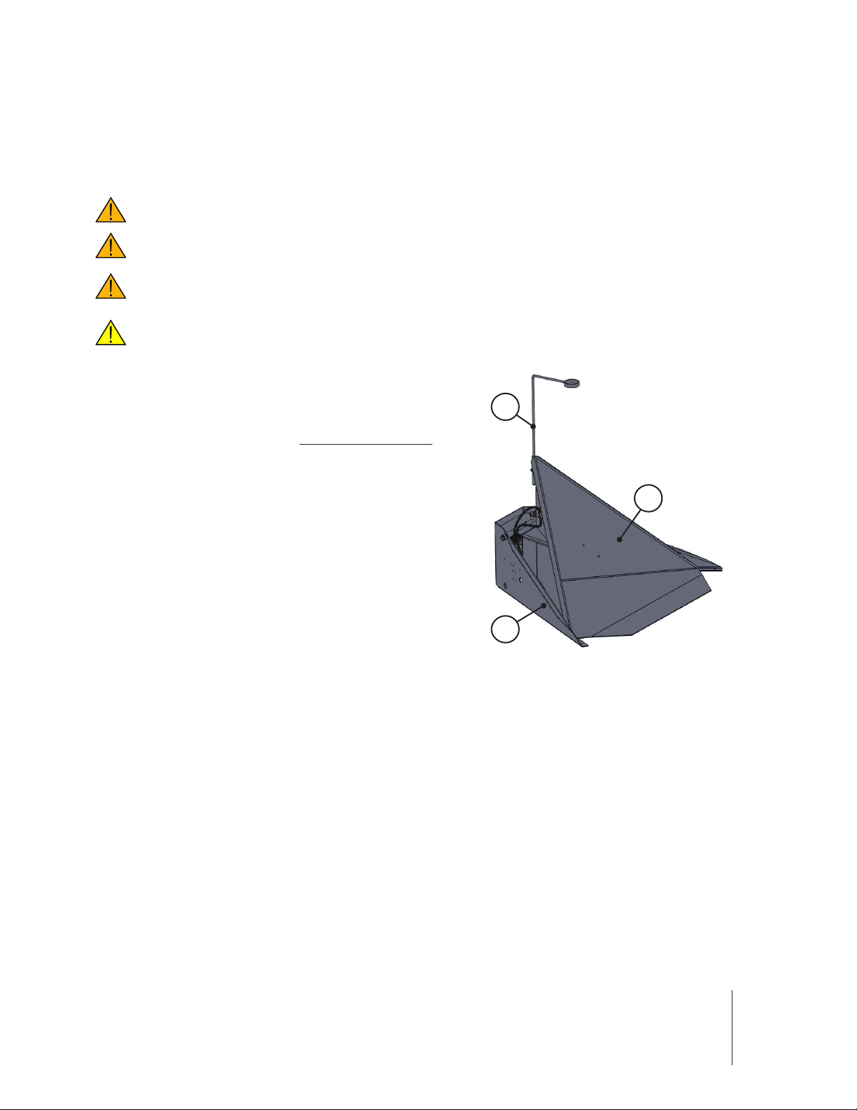
3. Fully lower the FLT bucket.
4. Shuto/disconnectthemainairsupply.Allowairtofullybleedfromequipment.
5. Identify and release stored energy as necessary.

REV I | 8/6/19
7
6. Ifapplicable:Shuto/disconnectthemainelectricalpowersource.
7. Perform your in-house lockout/tag-out procedure.
8. Verifythatallenergysourcesareintheo/neutralstate.

REV I | 8/6/19
8
4. Installation
WARNING:Installationmustonlybeperformedbyqualiedprofessionalswiththeappropriatecredentials
for all required tasks.
4.1 Pre-Shipment Planning
Prior to shipment of the equipment:
1. Ensure that your facility has an adequate foundation to support the equipment. Consider the
equipment weight, material weight, and torque when the equipment is operating.
2. Determine the appropriate anchoring method for the equipment.
3. Ensure that your facility entrances can accommodate the equipment.
4. Determine the equipment required to move the FLT, including vehicles and rigging. Allow only
qualiedprofessionalstooperatetheequipmentandmovetheFLT.
4.2 Inspection of Shipment
Upon receiving the equipment:
1. Ensure that all pieces of equipment are present and not damaged.
a. Report shipping damage to the carrier before the carrier leaves your facility. All claims must
beledbeforethecarrierleavestheunloadingsite.
b. Report any missing components immediately.
2. Remove shipping supports from the equipment (if present).
4.3 Installation Guidelines
NOTICE: The customer is responsible for evaluation and guarding of any open sides of the equipment.
NOTICE: All plumbing and wiring must meet or exceed all federal, state, and local codes/standards,
andmustbeinstalledbyqualiedpersonnel.
WARNING:Beforeuse,FLTmustbesecuredtooorusingfourholesinbottomofframe.Ifthecaster
package is installed on the FLT, the FLT unit should be lowered to the oor (casters raised) instead of
anchoring.
WARNING: The air regulator is pre-set to 43 PSI [2.96 bar] and cannot be adjusted to higher pressure.
Operating at a higher pressure can rupture airbag.
1. LeveltheFLT,thenanchorittotheoorusing(4)holesinbottomofframe.Ifthecasterpackage
isinstalledontheFLT,theFLTunit shouldbeloweredtotheoor(castersraised)insteadof
anchoring.
2. Ensure pneumatic hoses within the frame of the machine are secured to the frame (where possible)
and clear of the rotating bucket, pivot points, and/or any moving parts.
3. Connect air supply (50-100 PSI nominal; 3.45-6.89 bar) to ball valve.
4. Turn ball valve to open position to enable air pressure.
For information on installation and setup of major purchased components, refer to manufacturer
documentation.

REV I | 8/6/19
9
4.4 Retrot Packages
ForinformationoninstallationandsetupofCasterRetrot29-186andSafetyRatchetRetrot29-300
packages,refertocorrespondingRetrotsectionofthismanual.

REV I | 8/6/19
10
5. Sequence of Operation
5.1 Operating Sequence
WARNING: Do not stand behind bucket or put any part of your body under, in, or near bucket when bucket
is raising/tilting or raised/tilted.
WARNING: Machine operation occurs automatically. Do not place any part of the body on or near moving
devices/components of the machine.
WARNING: Do not adjust Gaylord position in bucket when bucket is raised—fully or partially. This can
result in the Gaylord tipping and falling from the bucket, which can cause personal injury. Lower the bucket
if adjustment of the Gaylord is required.
CAUTION: If repositioning the vacuum wand holder, support the vacuum wand holder before loosening
the screw securing it in place. This prevents the vacuum want holder from quickly lowering and potentially
causing personal injury.
NOTICE:Bucketmustbeatonoorbeforeloading.
1. Start with the FLT bucket (A) fully lowered.
2. LoadGaylordsoittstightly into rear corner of
bucket (A).
3. Lower vacuum wand holder (B) into hole on FLT
frame and tighten screw at base.
4. Insert vacuum wand into wand holder (B) and
into full Gaylord.
5. Placepedal/handvalveintheinateposition,as
described below.
As weight in Gaylord decreases, bucket lifts and
rotatesfromoorposition.Liftingbeginswhen
cargo weight is less than 900 lbs [408.2 kg] (*)
6. When Gaylord is empty, place control valve in
deateposition,asdescribedbelow,tolowerthe
bucket.
7. Unload the Gaylord from the bucket.
(*) IfthematerialintheGaylordhasalowowabilityorhighbulkdensity,theinitialtiltweightmay
beaected.MorematerialmayremainintheoutercorneroftheGaylord,causingthecontainer
to begin to tilt later than expected.
5.2 Foot Pedal Operation
NOTE: Pedal can be positioned on either side of frame for operation.
• Fullforward-Inatesairbagtoraisebucketwhencargoweightreducestolessthan900lbs
• Flat pedal - Holds bucket in current position
• Fullback-Deatesairbagandlowersbucket
5.3 Hand Valve Operation
• C1-Deatesairbagandlowersbucket
• N - Holds bucket in current position
• C2-Inatesairbagtoraisebucketwhencargoweightreducestolessthan900lbs
B
A
C
A) Bucket
B) Vacuum wand holder
C) Frame

REV I | 8/6/19
11
6. Maintenance
6.1 Considerations
The recommendations below are a guide; they are not all-inclusive. Use these recommendations, along
withthe OEM recommendations, to develop a preventative maintenance planthatis tting for the
environment of your equipment.
WARNING:NOpersons,otherthanqualiedpersonnel,shouldmaintainorservicethisequipment.
WARNING:Usecautionwhenservicinguidpowersystems.Impropermaintenanceproceduresinvolving
pneumatic or hydraulic systems can cause a device to move unexpectedly, resulting in equipment damage
or personnel injury. Safeguard or restrain moveable devices in accordance with applicable safety standards
before servicing.
WARNING: Before performing maintenance on this equipment, ensure that all energy sources are properly
isolated as described in the Safety–Energy Isolation section.
6.2 Maintenance Schedule
Periodicallygreasepivotpinthroughgreasettingoncenterofpivottube.
Periodically apply oil or lubricant to airbag pivot pin.
Refer to manufacturer documentation for maintenance of purchased components.
Replace damaged or worn components before operating FLT.
Inspect the airbag(s) monthly for the following items: dry-rot cracks, rub marks, deformation, abrasion,
or areas near which an accident occurred that may compromise the integrity of the airbag. If defect(s)
are observed, replace the airbag before returning the FLT to operation.
As applicable, inspect the safety ratchet monthly for the following items: worn pawl, worn gear teeth,
and loose hardware. Tighten loose hardware. If defect(s) are observed, replace the defective component.
Section continues on following page.

REV I | 8/6/19
12
6.3 Airbag Replacement
WARNING:NOpersons,otherthanqualiedpersonnel,shouldmaintainorservicethissystem.
WARNING: Before performing maintenance on this system, ensure that all energy sources are properly
isolated as described in the Safety–Energy Isolation section.
1. Ensure bucket (A) is empty and fully lowered.
2. Turnoandisolateenergysources,andperformin-houselock-out/tag-outprocedure.
3. Remove bucket pivot pin (D) from frame pivot tubes (B) and bucket pivot tube (C).
NOTE: Remove retaining bolts to allow removal of pivot pin.
4. Disconnect safety chain (H) from frame (D).
5. Disconnect airbag (H) from rear side of FLT frame (E) by removing nuts (G) from airbag bolts.
6. Disconnect air hose (K) from airbag.
7. Move bucket assembly (A) slightly forward from frame (E) to provide space for airbag removal.
8. Unbolt and remove airbag (H) from airbag bracket (I).
9. Replace the airbag as follows:
a. Locate new airbag (H) on airbag bracket (I), and replace and tighten bolts.
b. Move bucket assembly (A) into frame.
c. Re-connect air hose (K) to airbag.
d. Re-connect safety chain (F) to frame.
e. Insert bucket pivot pin (D) through frame and bucket pivot tubes (B), (C), then install
retaining bolt at each end of bucket pivot pin.
f. Replace and tighten nuts (G) on back of frame to re-connect airbag (H) to frame (E).
B
AD
C
I
F
E
G
G
H
A) Bucket
B) Frame Pivot Tubes (2)
C) Bucket Pivot Tube
D) Bucket Pivot Pin
E) Frame
F) Safety Chain/Nuts
G) Airbag Nuts (2)
H) Airbag
I) Airbag Bracket
J) Bucket Airbag Pivot
K) Air Hose to Airbag
J
K

REV I | 8/6/19
13
7. Caster Retrot Package
7.1 Installation
WARNING:NOpersons,otherthanqualiedpersonnel,shouldmaintainorservicethissystem.
WARNING: Before performing maintenance on this system, ensure that all energy sources are properly
isolated as described in the Safety–Energy Isolation section.
1. Ensure bucket is empty and fully lowered.
2. Turnoandisolateenergysources,andperformin-houselock-out/tag-outprocedure.
3. Remove the bucket from the FLT frame as follows:
a. Remove nuts (on back of frame) holding airbag to frame.
b. Remove nuts (on back of frame) holding safety chain to frame.
c. Remove bucket pivot pin from frame and bucket pivot tubes. NOTE: Retaining bolts at each
end must removed to allow bucket pivot pin to be removed.
d. Move bucket (with airbag attached) forward, out of frame leaving enough room to work.
NOTE: As needed, FLT hand valve can be un-bolted from bucket for additional air hose
length when moving bucket out of frame.
4. Mount the caster assemblies to the FLT frame as follows:
a. Facing rear outside of the frame, with caster retracted, drill holes and mount rear caster
assembly to center rear side of frame.
b. Facing rear outside of the frame, with caster retracted, place left caster assembly under lip
of left hand side of frame and move it forward until caster assembly stops. Drill holes and
mount left caster assembly.
c. Facing rear outside of the frame, with caster retracted, place right caster assembly under lip
of right hand side of frame and move it forward until caster assembly stops. Drill holes and
mount right caster assembly.
5. Install the caster hand valve as follows:
a. Facing rear outside of the frame, drill and mount caster hand valve on right hand side of
frame.
b. Remove hose and hose barb from existing FLT air regulator assembly. NOTE: The opposite
end of this hose is connected to the FLT hand valve inlet port.
c. Insert 1/4" nipple into regulator.
d. Thread 1/4" NPT tee into nipple.
e. Install 1/4" hose barb on each end of tee.
f. Connect 1/4" hose from one of the two hose barbs (installed in previous step) to caster hand
valve inlet port (left hand port).
g. Re-connect hose disconnected in step b. to second hose barb (installed in step e.). The
opposite end of this hose is connected to the FLT hand valve inlet port.
h. Using clips, attach hoses to frame.
6. Re-install bucket in FLT frame as follows:
a. Carefully move bucket (with airbag assembly attached) back into FLT frame, aligning frame
and bucket pivot tubes.
b. Insert bucket pivot pin through frame and bucket pivot tubes, then re-install retaining bolts.
c. Facing rear outside of the frame, re-install nuts (on back of frame) holding airbag to frame.

REV I | 8/6/19
14
d. Facing rear outside of the frame, re-install nuts (on back of frame) holding safety chain to
frame.
e. If FLT hand valve was removed from bucket, fasten FLT hand valve to bucket.
7.2 Operation
WARNING: If the caster package is installed on the FLT, the FLT unit should be lowered to the oor
(casters raised) before operation.
CAUTION: Casters are only for use in moving FLT when bucket is EMPTY.
CAUTION: Test caster system before using.
7.2.1 Hand Valve Operation
Hand valve positions include:
• C1-Deatescasterairbags,loweringFLT(castersup)
• N - Holds casters in place when air supply is removed for movement of FLT
• C2-Inatescasterairbags,raisingFLT(castersdown)

REV I | 8/6/19
15
8. Safety Ratchet Retrot Kit
8.1 Installation
WARNING:NOpersons,otherthanqualiedpersonnel,shouldmaintainorservicethissystem.
WARNING: Before performing maintenance on this system, ensure that all energy sources are properly
isolated as described in the Safety–Energy Isolation section.
Components diagrams are located on the next page.
1. Ensure bucket (I) is empty and fully lowered.
2. Turnoandisolateenergysources,andperformin-houselock-out/tag-outprocedure.
3. Unbolt hand valve (A) from bucket (I).
4. Remove bucket pivot pin (K) from frame pivot tubes (B) and bucket pivot tube (J).
NOTE: Remove retaining bolts to allow removal of pivot pin.
5. Disconnect safety chain (H) from frame (D).
6. Remove airbag pivot pin (F) from airbag bracket (E). NOTE: Remove cotter pin from either end
of airbag pivot pin to allow removal.
7. Move bucket (I) away from frame (D) then orient bucket to allow access to rear corner (Figure 5).
8. Mount ratchet assembly (M, N, O) as follows:
a. Locate ratchet assembly (M, N, O) on the outer rear corner of the bucket (I) as shown in
Figure 5.
b. Trace the (8) holes on the ratchet bracket (M) onto the bucket (I).
c. Center punch holes traced in previous step.
d. With 21/64" drill bit, drill clearance holes into pilot holes.
e. Using 5/16" bolts and 5/16" locknuts, fasten the ratchet assembly (M, N, O) in place.
9. Mount ratchet gear (P) as follows:
a. Facing inside of frame (D), locate ratchet gear (P) on holes in frame—location (Q). The
ratchet gear should be oriented teeth down.
b. Install5/16"bolts,lockwashers,andatwashers(inorderlisted),liftratchetgear(P)ashigh
as high as possible, then loosely fasten gear ratchet in place. NOTE: Permanent tightening
willtakeplaceafternaladjustment.
10. Re-connect bucket (I) to frame (D) as follows:
a. Move the bucket (I) into the inside of frame (D), and align bucket airbag pivot (L) with holes
in airbag bracket (E). Insert airbag pivot pin (F) and insert cotter pins through pivot pins.
b. Re-connect safety chain (H).
c. Insert bucket pivot pin (K) through frame and bucket pivot tubes (B), (J); then install retaining
bolt at each end of bucket pivot pin. NOTE: Pivot pins can be lubricated at this time.
d. Fasten hand valve (A) in original location on bucket.
Procedure continues after Component Diagrams page (next).

REV I | 8/6/19
16
8.1.1 Components Diagrams
BA
D
C
KJ
I
F
H
E
B
G
H
F
E
G
D
I
D
F
E
G
B
H
L
M
O
N
L
P
J
A) Hand Valve
B) Frame Pivot Tubes (2)
C) Ball Valve & Regulator
D) Frame
E) Airbag Bracket
F) Airbag Pivot Pin
G) Airbag
H) Safety Chain
I) Bucket
J) Bucket Pivot Tube
K) Bucket Pivot Pin
L) Bucket Airbag Pivot
M) Ratchet Bracket
N) Ratchet Cylinder
O) Ratchet Pawl
P) Ratchet Gear
Q) Ratchet Gear Location
Figure 1 Figure 2
Figure 3 Figure 5
Figure 4
PQ

REV I | 8/6/19
17
8.1.2 Air Connection—Hand Valve (29-950)
Connect air to the ratchet as follows:
1. Connect the end of the hose segment to the air inlet on the ratchet cylinder.
2. Run air hose under bucket where bucket pivot pin is located. Attach hose to clips at
current hose junction.
3. Remove hex plug from top port (R) on hand valve (V).
4. Thread hose barb into top port (R) on hand valve, then connect hose to barb.
NOTE: The bottom port (T) connects to the airbag, and the left hand port (S) connects to
theregulator.Amuerisinstalledintherighthandport(U).
U
T
S
RFigure 6
V
R) Top Port
S) Left Hand Port
T) Bottom Port
U) Right Hand Port
V) Hand Valve
8.1.3 Air Connection—Food Pedal (29-900)
Connect air to the ratchet as follows:
1. Connect the end of the hose segment to the air inlet on the ratchet cylinder.
2. Run air hose under bucket where bucket pivot pin is located. Attach hose to clips at
current hose junction.
3. Unbolt foot pedal from mount plate.
4. Removehexplugfromfrontlefthandportonfootpedalandreplacewithmuer.
5. Remove hex plug from front right hand port on foot pedal. Install the following items
in the order listed: hex nipple, female elbow, and hose barb. Connect hose to hose barb.
NOTE: The rear left hand port connects to the regulator and the rear right hand port
connects to the airbag.
6. Bolt foot pedal to mount plate.
8.1.4 Final Adjustments
1. Restore air pressure to FLT.
2. Using foot pedal or hand valve, raise the empty FLT bucket.

REV I | 8/6/19
18
3. Lower the FLT bucket and observe ratchet operation. The pawl should move as closely
along the ratchet gear as possible without touching the ratchet gear.
4. With the ratchet gear positioned as close as possible to the pawl without touching it,
tighten the bolts to secure the ratchet gear in place.

REV I | 8/6/19
19
9. Warranty
(Seller) warrants products manufactured by it and supplied hereunder to be free of defects in materials
and workmanship under normal use and proper maintenance for a period of one (1) year from the date
of shipment. If within such period, any such products shall be proved to Seller’s sole discretion to be
defective, such products shall be at Seller’s option repaired or replaced. Seller shall be responsible for
labor charges in connection with repair or replacement for a period of ninety (90) days from date of
shipment, but only for repair or replacement within the continental United States and Canada. All other
labor charges shall be billed to Buyer at Seller’s then prevailing rates, including travel and lodging
expenses. Seller’s obligation and Buyer’s exclusive remedy hereunder shall be limited to such repair
and replacement and shall be conditioned upon Seller receiving written notice of any alleged defect
no later than ten (10) days after its discovery within the warranty period. At Seller’s option, the Seller
may require return of such products to Seller when such return is feasible. Seller reserves the right to
satisfy all of its warranty obligations by reimbursing Buyer for all amounts Buyer has paid to Seller
for such product upon which Buyer shall immediately return the product(s) to Seller. The foregoing
warranty is not applicable to: (i) accessories and components not manufactured by Seller, which are
warranted only to extent, if any, of the manufacturer’s warranty for such accessories and components
(but the warranty term for any such warranty shall be the expiration date of such warranty, or one year
fromdateofshipment,whicheveristhersttooccur),or(ii)damagescausedbyshipping.Sellershall
be responsible for freight charges for replacement parts only if shipped within the continental United
States or Canada.
The foregoing warranty is exclusive and in lieu of all other express and implied warranties
(except of title) including but not limited to implied warranties of merchantability, tness for a
particular purpose, performance, or otherwise. All other warranties are expressly disclaimed.
Buyer agrees that in no event shall the Seller be liable for claims (based upon breach of express
or implied warranty, negligence, product liability, or otherwise) for any other damages, whether
direct, indirect, immediate, incidental, foreseeable, consequential, special or based on any other
claim.
Table of contents
Other Vestil Power Tools manuals