Vestil PEL-88-A-SWA User manual

Rev. 5/19/2015 PEL-88-A-SWA, MANUAL.doc
Copyright 2015 Vestil Manufacturing Co. Page 1 of 11
PEL-88-A-SWA & PEL-100-A-SWA Wrapping Machines
Use and Maintenance Manual
Receiving instructions:
After delivery, IMMEDIATELY remove the packaging from the product in a manner that preserves the packaging and
maintains the orientation of the product in the packaging; then inspect the product closely to determine whether it
sustained damage during transport. If damage is discovered during the inspection, immediately record a complete
description of the damage on the bill of lading. If the product is undamaged, discard the packaging.
NOTES:
1) Compliance with laws, regulations, codes, and non-voluntary standards enforced in the location where the product is
used is exclusively the responsibility of the owner/end-user
2) VESTIL is not liable for any injury or property damage that occurs as a consequence of failing to apply either:
a) Instructions in this manual; or b) information provided on labels affixed to the product. Neither is Vestil responsible for
any consequential damages sustained as a result of failing to exercise sound judgment while assembling, installing, using
or maintaining this product.
Table of Contents
Product Specifications……………….…………………..…………………………………………………………………………2
Signal Words….……………………..……………………………………………………………………………………………...2
Safe Use Recommendations……………………………………………………………..………………………………………. 3
FIG. 1: PEL-88-A-SWA exploded parts diagram & bill of materials…………………………………...………………………4-5
FIG. 2: Electrical system circuit diagram…………………………………………………………………………………………5
FIG. 3: PEL-100-A-SWA exploded parts diagram & bill of materials………………………………………………………… 6-7
Loading Stretch Wrap………………………………………………………………………………………………………………8
Operation Instructions………………………………………………………………………………………………...……………8
System Power……………………………………………………………………………………………………………………… 9
Inspections & Maintenance……………………………………………………………………………………………………….. 9
Troubleshooting Guide……………………………………………………………………………………………………………..10
Labeling Diagram……...……………………………………………………………………………………………………..……. 10
VESTIL MANUFACTURING CORP.
2999 North Wayne Street, P.O. Box 507, Angola, IN 46703
Telephone: (260) 665-7586 -or- Toll Free (800) 348-0868
Fax: (260) 665-1339
www.vestilmfg.com e-mail: [email protected]

Rev. 5/19/2015 PEL-88-A-SWA, MANUAL.doc
Copyright 2015 Vestil Manufacturing Co. Page 2 of 11
Product specifications:
Dimensions and other product specifications appear in the diagrams and table below.
Model A B C D E Net weight
PEL-88-A-SWA
325/8 in.
703/8 in.
52 in. 783/4 in.
437/8 in.
210.1 lb.
95.5 kg
PEL-100-A-SWA
325/8 in.
851/8 in.
67 in. 939/16 in.
437/8 in.
217.0 lb.
98.7 kg
SIGNAL WORDS:
This manual uses SIGNAL WORDS to indicate the likelihood of personal injuries, as well as the probable seriousness
of those injuries, if the product is misused in the ways described. Other signal words call attention to uses of the
product likely cause property damage. The signal words used appear below along with the meaning of each word:
Identifies a hazardous situation which, if not avoided, WILL result in DEATH or SERIOUS
INJURY. Use of this signal word is limited to the most extreme situations.
Identifies a hazardous situation which, if not avoided, COULD result in DEATH or SERIOUS
INJURY.
Indicates a hazardous situation which, if not avoided, COULD result in MINOR or MODERATE
injury.
Identifies practices likely to result in product/property damage, such as operation that might
damage the product.
Each person who assembles, installs, uses, or maintains this product should read the entire manual in advance and
fully understand the directions. If after reading the manual you do not understand an instruction, ask your supervisor
or employer for clarification, because failure to adhere to the directions in this manual might result in serious personal
injury.
A
B
C
D
E

Rev. 5/19/2015 PEL-88-A-SWA, MANUAL.doc
Copyright 2015 Vestil Manufacturing Co. Page 3 of 11
Safe Use Recommendations:
We strive to identify all hazards associated with the use of our products. However, material handling is dangerous and
no manual can address every risk. The end-user ultimately is responsible for exercising sound judgment at all times.
Material handling is dangerous. Improper or careless operation of this wrapping machine might result
in serious personal injuries.
Failure to read and understand the entire manual before assembling, using or servicing the product
constitutes misuse.Read the manual whenever necessary to refresh your understanding of proper use and
maintenance procedures.
DO NOT use the wrapping machine unless it is in normal operating condition. Inspect the unit as described in the
inspection instructions on p. 9 to determine whether it is functioning normally. DO NOT use the machine unless it
passes every part of the inspection or until it is restored to normal operating condition.
DO NOT use the machine to lift, carry, or transport items or people.
Always watch the carriage carefully while raising and lowering it.
This crane is designed for material handling ONLY. DO NOT use the crane to lift people.
ALWAYS load the wrapping material properly (see “Loading stretch wrap” on p. 8).
If repairs are necessary, ONLY install manufacturer-approved replacement parts.
The carriage (see item no. 2 on p. 4 & 6) should elevate and lower smoothly. Watch for binding or jerky movement
and listen for unusual noises. Remove the unit from service if you observe anything abnormal.
DO NOT use this wrapping machine UNLESS all labels are in place & readable (see “Labeling diagram” on p. 11.)
DO NOT modify this product in any way. Modifying the machine automatically voids the limited warranty and might
make it unsafe to use.
Proper use and maintenance are essential for this product to function properly.
Always use this product in accordance with the instructions in this manual.
Periodically lubricate moving parts.
Keep the product clean & dry at all times. Always store the unit inside.
Only use approved replacement parts. To order replacement or spare parts for this equipment, contact the factory.

Rev. 5/19/2015 PEL-88-A-SWA, MANUAL.doc
Copyright 2015 Vestil Manufacturing Co. Page 4 of 11
FIG. 1: PEL-88-A-SWA exploded parts diagram and bill of materials
Detail view of carriage rollers:
4
Detail view inside motor housing:
2
Item no. 12 (touchpad control):
Speed gauge
indicates
current travel
speed setting
These
buttons
control
vertical
position
of the
carriage
FASTER and SLOWER buttons control
the speed the carriage travels up and
down the mast
Battery charge meter
indicates percent of
full charge remaining
Turns power
on and off.
Status light
indicates
whether
power is ON
or OFF.
Swivel caster with
brake (item no. 22):

Rev. 5/19/2015 PEL-88-A-SWA, MANUAL.doc
Copyright 2015 Vestil Manufacturing Co. Page 5 of 11
PEL-88-A-SWA Bill of Materials:
FIG. 2: Electrical system circuit diagram
Item
no. Part no. Description Quantity
Item
no. Part no. Description Quantity
1 42-514-002
Weldment, frame (upright
portion = “mast”)
1 14 21-034-025
Flanged inlet sleeve with locking
ring
1
2 42-538-001
Weldment, carriage 1 15 11012
1
/4in. – 20 x 2
1
/4in. HHCS #2
zinc-plated bolt
4
3 37024
3/8in. Nylock insert nut 6 16 20-538-002
Assembly, carriage, stretch wrap
carrier
1
4 20-110-008
Roller bearings 4 17 20-525-001
Weldment, handle 1
5 11105
3
/
8
in. – 16 x 1in. hex head bolt 4 18 20-016-076
Bracket, roller 2
6 11003
1
/4in. – 20 x
3
/4in. hex head
bolt
4 19 33008
3
/8in. flat washer 20
7 37018
1/4in. – 20 lock nut 2 20 11109
3
/8in. – 16 x 1
1
/2in. HHCS #2
zinc-plated bolt
4
8 21-135-001
Motor 1 21 16-132-155
Caster, swivel, stem, HR-4/1.25-
SLB-S
2
9 21-139-001
12V battery 2 22 16-132-156
Caster, swivel, with brake, HR-4-
1.25-SLB-S
2
10 21-156-006
Accessories, Electrical control
box, Curtis 1210-2401
1 23 33011
1
/2in. flat washer 4
11 21-034-010
24V battery charger 1 24 37030
1
/
2
in. – 13 Nylock nut 4
12 21-156-002
Electronic touchpad control 1 25 11119
3
/8in. – 16 x 4in. HHCS #2 zinc-
plated hex head bolt
2
13 21-024-042
Motor cover 1 26 16-132-009
PP-4/1.25-W 4

Rev. 5/19/2015 PEL-88-A-SWA, MANUAL.doc
Copyright 2015 Vestil Manufacturing Co. Page 6 of 11
FIG. 3: PEL-100-A-SWA exploded parts diagram (bill of materials on following page)
View of drive components with motor housing removed:
Item no. 8 (touchpad control):
These
buttons
control
vertical
position
of the
carriage
FASTER and SLOWER buttons control
the speed the carriage travels up and
down the mast
Speed gauge
indicates
current travel
speed setting
Battery charge meter
indicates percent of
full charge remaining
Turns power
on and off.
Status light
indicates
whether
power is ON
or OFF.
Detail view of carriage
rollers (inside mast):
Swivel caster with
brake (item no. 22):
3
2

Rev. 5/19/2015 PEL-88-A-SWA, MANUAL.doc
Copyright 2015 Vestil Manufacturing Co. Page 7 of 11
PEL-100-A-SWA Bill of Materials:
Item
no. Part no. Description Quantity
Item
no. Part no. Description Quantity
1 42-514-003
Weldment, frame (upright
portion = “mast”) 1 14 33008
3
/8in. flat washer 20
2 42-538-001
Weldment, carriage 1 15 16-132-155
Caster, swivel, stem, HR-4/1.25-
SLB-S 2
3 20-110-008
Roller bearings 4 16 16-132-156
Caster, swivel, with brake, HR-4-
1.25-SLB-S 2
4 11003
1
/4in. – 20 x
3
/4in. hex head
bolt 4 17 11109
3
/8in. – 16 x 1
1
/2in. HHCS #2
zinc-plated bolt 4
5 11105
3
/
8
in. – 16 x 1in. hex head bolt 4 18 16-132-009
PP-4/1.25-W 4
6 37024
3/8in. Nylock insert nut 6 19 11119
3
/8in. – 16 x 4in. HHCS #2 zinc-
plated hex head bolt 2
7 21-135-001
Motor 1 20 37018
1
/
4
in. – 20 lock nut 2
8 21-156-002
Electronic touchpad control 1 21 37030
1
/
2
in. – 13 Nylock nut 4
9 21-034-010
24V battery charger 1 22 20-538-002
Assembly, carriage, stretch wrap
carrier 1
10 21-139-001
12V battery 2 23 20-016-076
Bracket, roller 2
11 21-034-025
Flanged inlet sleeve with
locking ring 1 24 20-525-001
Weldment, handle 1
12 11012
1
/4in. – 20 x 2
1
/4in. HHCS #2
zinc-plated bolt 4 25 33011
1/2in. flat washer 4
13 33004
1
/4in. type A narrow flat
washer 2 26 21-156-006
Accessories, Electrical control
box, Curtis 1210-2401 1
27 21-024-042
Motor cover 1

Rev. 5/19/2015 PEL-88-A-SWA, MANUAL.doc
Copyright 2015 Vestil Manufacturing Co. Page 8 of 11
Loading Stretch Wrap:
The stretch wrap holder is easily disassembled and reassembled to facilitate rapid loading of new rolls and removal of
empty rolls. To assemble the stretch wrap holder, follow steps 1-5 below. The holder will accommodate rolls of
wrapping material up to 20in. long. [NOTE: Numbers in parentheses () in steps 1-5 below correspond to item
numbers.]
Stretch wrap holder assembly
3
5
1
4
1
Item
no.
Part no. Description Quantity
1 20-014-006 Wrap retainer 2
2 33426
3
/
4
” – 10ga. machinery bushing 5
3 20-538-001 Carriage weldment 1
4 20-538-003 Threaded spindle 1
5 20-145-008 Spindle handle 1
Item no. 2
not shown
Step 1: Slide 3 machinery
bushings (2) onto the shaft
of the spindle (4).
Step 2: Install a wrap retainer (1). The
bushings installed in step 1 will fit inside
a cavity in the underside of the retainer.
Machinery
bushing
Retainer
Step 3: Install a roll of stretch wrap;
then install the other retainer.
Step 4: Insert the threaded end of the
spindle through the hole in the end of
the carriage arm; then slide 2 more
machine bushings onto the spindle.
Step 4: Wind the spindle
handle onto the end of the
spindle and tighten it against
the bushings.
Roll of
stretch
wrap
Wrap
retainer
Machinery
bushings
Spindle
handle
Carriage
arm
NOTE: The tightness of
the handle connection
determines the degree to
which the wrap stretches.
The tighter the
connection the more the
wrap will stretch.
Operation:
This product is not self-propelled. To move the unit, lower the carriage; then push it carefully to the work location.
Vertical travel of the carriage is controlled electronically via the touchpad (see item no. 12 on p. 4). Use the
RAISE and LOWER buttons to adjust the vertical position of the carriage as the application requires.
The travel speed of the carriage is adjustable. Press the FASTER button to increase travel speed, or press the
SLOWER button to decrease speed. The SPEED gauge between the buttons indicates the current speed setting.
To wrap an object, attach the free end of the wrap to it. Push the wrapping machine around the object to
dispense wrap. When the wrapping process is finished, cut the wrap (for example with a utility knife). Lower the
carriage and move the unit to its storage location. Apply the caster brakes (see FIG.
Store the wrapping machine in a dry, indoor location to protect the electronic components.

Rev. 5/19/2015 PEL-88-A-SWA, MANUAL.doc
Copyright 2015 Vestil Manufacturing Co. Page 9 of 11
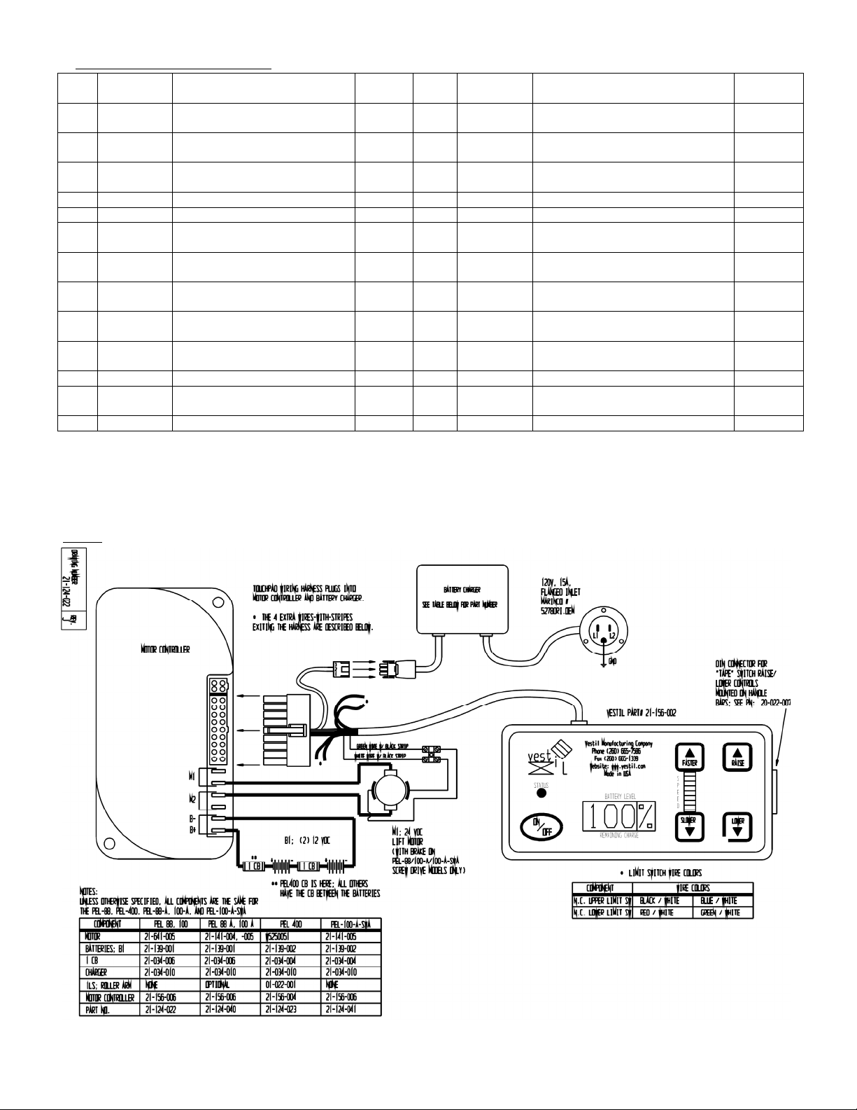
System power:
Power is supplied by two 12V batteries. Both batteries are
completely sealed and are therefore maintenance free.
To recharge the batteries, every wrapping machine includes a
24V charger. The charger operates on 115 VAC and requires a
3-prong (grounded) extension cord. The charger monitors and
reacts to the battery voltage during the recharging process.
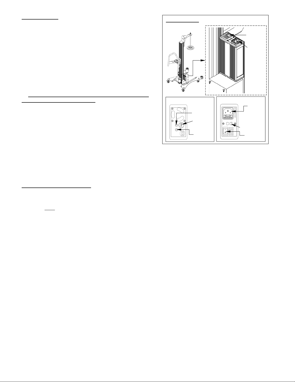
When the batteries are fully charged, a green LED on the bottom
of the charger turns on (see diagrams to the right). The battery
charge gauge (see “Touchpad control” on p. 6) displays the
amount of battery charge remaining as a percentage of full
(100%) charge. To determine the true level of charge, wait at
least 1/2 hour after turning off the charger. If the voltage is
12.65V or more, then the batteries are fully charged.
Charge the batteries for at least 4 hours before using the
wrapping machine for the first time.
How frequently the batteries require charging depends on the
load applied to the batteries (i.e. how many times the carriage is
moved and how quickly—faster speed will drain the battery more
rapidly) and the duration and frequency of use. Experience will
dictate when the batteries should be charged.
Whenever recharging is begun, it should continue until the
batteries are fully charged. Do not interrupt the charging cycle.
Fully charging the batteries every time recharging is undertaken
maximizes battery life.
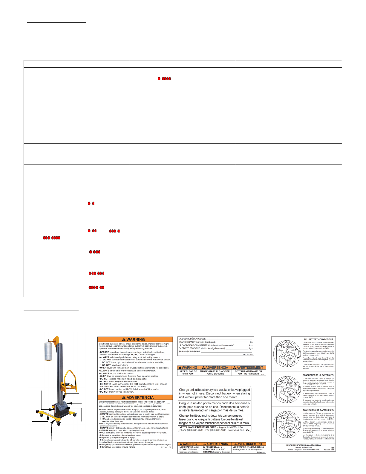
Recommendations regarding battery charging: 1) Recharge the batteries at least once every 2 weeks; 2) Leave
the charger plugged in when the unit is not in use (the battery charger can remain connected to the batteries for long
periods without causing damage to the batteries); 3) Disconnect the batteries when the unit will be unused for 1 month
or longer; 4) ALWAYS keep the wrapping machine dry.
Inspections & Maintenance:
If any of the inspections described below reveal problems, tag the unit “Out of Service”. Restore the machine to
normal operating condition BEFORE using it again.
A. Before each use, inspect the following components. Each component must be in normal operating condition. To
establish normal operating condition, make a thorough record of the appearance, sound, and function of the various
parts of the wrapping machine when you first receive it. Compare later observations to the record to determine
whether the machine is in normal operating condition.
1. Frame: examine the frame, roller brackets, and handle weldment. Look for damaged welds, warps, cracks, or
other deformations.
2. Casters: examine each caster. Confirm that casters are not severely worn, swivel freely, and that the brakes
firmly engage the wheels.
3. Carriage mechanism: cycle the carriage by raising it to the top of the mast and then lowering it completely. The
carriage should move smoothly and at a uniform rate up-and-down the mast. Watch for binding and listen for
unusual sounds.
4. Fasteners: check bolts and nuts. Make sure all fasteners are tightly connected.
5. Roller bearings: look inside the channel of the mast and examine the roller bearings of the carriage (see FIGS.
1 and 3). Clean the interior of the mast to remove debris that might interfere with the rollers.
B. At least once per month:
1. Wiring: inspect the electrical system and look for loose connections and damage.
2. Clean the machine: remove dirt and other matter from all surfaces.
3. Labels: refer to the “Labeling Diagram” on p. 10. Make sure that all labels are in place and readable.
4. Batteries: remove corrosion from the posts if present.
Battery charger:
Power
switch
Outlet for
charging
cord
Bottom face of charger:
Top face of charger:
Charging
LED
Power
LED
6.3A/250V
fuse
Power
switch
Flanged
inlet for
charging
cord
115-230VAC
selectable

Rev. 5/19/2015 PEL-88-A-SWA, MANUAL.doc
Copyright 2015 Vestil Manufacturing Co. Page 10 of 11
Troubleshooting guide:
The following table describes the most common issues that occur with these wrapping machines. If your unit
experiences a problem not included in this guide, contact the factory for assistance.
NOTE: The touchpad is not serviceable. DO NOT open the touchpad or attempt to correct a problem you
believe might be caused by a touchpad malfunction. Doing so voids the Limited Warranty (see p. 11). Contact
the factory to discuss all problems related to the touchpad.
Issue: Explanation Remedy
1) I press the UP or DOWN button
on the touchpad but nothing
happens.
a. Battery voltage too low. LED
flashes:
b. Faulty wiring, e.g. broken wire in
circuit.
c. If using optional hand control, plug
loose in touchpad socket.
d. Problem with motor or control.
e. Battery charger still plugged into
wall socket.
f. Circuit breaker or fuse blown.
a. Charge battery.
b. Inspect wiring. Perform circuit
continuity checks with meter (see
FIG. 2 on p. 5).
c. Unplug hand control and reinsert
plug into socket on touchpad.
d. See “Motor controller Diagnostics”.
e. Unplug charger.
f. Rest circuit breaker or replace fuse.
2) I press UP or DOWN and can
hear the motor humming, but the
carriage does not move.
g. Battery voltage is low.
h. Load applied to carriage too heavy.
g. Charge battery.
h. Reduce load.
3) Carriage stops moving before it
reaches fully raised or fully
lowered position.
i. Battery voltage is low.
j. Roller bearings obstructed or
binding.
k. Load applied to carriage too heavy.
i. Charge battery.
j. Inspect roller track for debris or
objects interfering with rollers.
k. Examine carriage; reduce load.
4) Touchpad does not respond to any
input. LED flashes:
l. Motor temperature either exceeds
(>92°C) or below (-25°C) threshold
operating temperature.
l. Check load applied to carriage.
Reduce, if necessary.
Cease use to allow motor to cool.
Increase ambient temperature.
5) Touchpad does not respond to any
input. LED flashes: or
or
m. Throttle input wire open or
shorted.
n. Throttle pot defective.
m. Check wiring. Confirm all
connections are sound.
n. Contact factory.
6) Touchpad does not respond to any
input. LED flashes:
o. Speed limit pot wires broken or
shorted.
p. Broker speed limit potentiometer.
o. Check wiring. Confirm all
connections are sound.
p. Contact factory.
7) Touchpad does not respond to any
input. LED flashes:
q. Controller failure; low battery
voltage.
q. Replace battery.
8) Touchpad does not respond to any
input. LED flashes:
r. Short in motor or in motor wiring.
s. Controller failure.
r. Check wiring. Confirm all
connections are sound.
s. Contact factory.
C
A
B
D
E
F
A: Label 527
B: Label 287
C: Label 208
D: Label 454
E: Label 212
F: Label 399 (inside housing)
Labeling diagram:
The unit should always be labeled as shown in the diagram below. Replace all labels that become damaged or
unreadable.

Rev. 5/19/2015 PEL-88-A-SWA, MANUAL.doc
Copyright 2015 Vestil Manufacturing Co. Page 11 of 11
LIMITED WARRANTY
Vestil Manufacturing Corporation (“Vestil”) warrants this product to be free of defects in material and workmanship
during the warranty period. Our warranty obligation is to provide a replacement for a defective original part if the part
is covered by the warranty, after we receive a proper request from the warrantee (you) for warranty service.
Who may request service?
Only a warrantee may request service. You are a warrantee if you purchased the product from Vestil or from an
authorized distributor AND Vestil has been fully paid.
What is an “original part”?
An original part is a part used to make the product as shipped to the warrantee.
What is a “proper request”?
A request for warranty service is proper if Vestil receives: 1) a photocopy of the Customer Invoice that displays the
shipping date; AND 2) a written request for warranty service including your name and phone number. Send requests
by any of the following methods:
Mail Fax Email
2999 North Wayne Street, PO Box 507 Phone
Angola, IN 46703 (260) 665-7586
In the written request, list the parts believed to be defective and include the address where replacements should be
delivered.
What is covered under the warranty?
After Vestil receives your request for warranty service, an authorized representative will contact you to determine
whether your claim is covered by the warranty. Before providing warranty service, Vestil may require you to send the
entire product, or just the defective part or parts, to its facility in Angola, IN. The warranty covers defects in the
following original dynamic components: motors, hydraulic pumps, electronic controllers, switches and cylinders. It
also covers defects in original parts that wear under normal usage conditions (“wearing parts”), such as bearings,
hoses, wheels, seals, brushes, and batteries.
How long is the warranty period?
The warranty period for original dynamic components is 1 year. For wearing parts, the warranty period is 90 days. The
warranty periods begin on the date when Vestil ships the product to the warrantee. If the product was purchased from
an authorized distributor, the periods begin when the distributor ships the product. Vestil may, at its sole discretion,
extend the warranty periods for products shipped from authorized distributors by up to 30 days to account for shipping
time.
If a defective part is covered by the warranty, what will Vestil do to correct the problem?
Vestil will provide an appropriate replacement for any covered part. An authorized representative of Vestil will contact
you to discuss your claim.
What is not covered by the warranty?
1. Labor;
2. Freight;
3. Occurrence of any of the following, which automatically voids the warranty:
Product misuse;
Negligent operation or repair;
Corrosion or use in corrosive environments;
Inadequate or improper maintenance;
Damage sustained during shipping;
Collisions or other incidental contacts causing damage to the product;
Unauthorized modifications: DO NOT modify the product IN ANY WAY without first receiving written
authorization from Vestil. Modification(s) might make the product unsafe to use or might cause excessive and/or
abnormal wear.
Do any other warranties apply to the product?
Vestil Manufacturing Corp. makes no other express warranties. All implied warranties are disclaimed to the extent
allowed by law. Any implied warranty not disclaimed is limited in scope to the terms of this Limited Warranty.
Other manuals for PEL-88-A-SWA
1
This manual suits for next models
1
Table of contents
Other Vestil Stretch Wrapping System manuals