manuals.online logo
Brands
  1. Home
  2. •
  3. Brands
  4. •
  5. Vestil
  6. •
  7. Truck
  8. •
  9. Vestil LM-Series User manual

Vestil LM-Series User manual

01/11 rev. 6/11/2020 LM MANUAL
Table of Contents Copyright 2020 Vestil Manufacturing Corp.
LM-Series and LMS-Series Fork Truck Attachments
Instruction Manual
Receiving Instructions
After delivery, remove the packaging from the product. Inspect the product closely to determine whether it
sustained damage during transport. If damage is discovered, record a complete description of
it on the bill of lading. If
the product is undamaged, discard the packaging.
NOTE: The end-user is solely responsible for confirming that product design, use, and maintenance comply with
laws, regulations, codes, and mandatory standards applied where the product is used.
Technical Service & Replacement Parts
For answers to questions not addressed in these instructions and to order replacement parts, labels,
and
accessories, call our Technical Service and Parts Department at (260) 665-7586. The department
can also be
contacted online at http://www.vestilmfg.com/parts_info.htm.
Electronic copies of Instruction Manuals
Additional copies of this instruction manual may be downloaded from https://www.vestil.com/page- manuals.php
Table of Contents Table of Figures
Signal Words…………….…………..… 2Fig. 1: LM-1T & -1NT Exploded Views, Parts Lists, Centers of Gravity……….. 3, 4, 5, 6
Safety Instructions………………..…… 2Fig. 2: LM-OBT & -OBNT Exploded Views, Parts Lists, Centers of Gravity...... 7, 8, 9, 10
National Standards……..……………...2Fig. 3: LM-HRT & -HRNT Exploded Views, Parts Lists, Centers of Gravity……11, 12, 13, 14
Loading & Using the Boom…. 23, 24, 25 Fig. 4: LM-EBT & -EBNT Exploded Views, Parts Lists, Centers of Gravity…….15, 16, 17, 18
Record of Satisfactory Fig. 5: LMS-EBT-46 & -EBNT-46 Exploded Views, Parts Lists, Centers
Condition…………………………...… 25 of Gravity……………………………………………………………………… 19, 20, 21, 22
Load Tests………………………………25
Inspections……………………………...26
Maintenance…………………………… 26
Labeling Diagram……………………… 27
Limited Warranty…………..………….. 28
LM-HRT &
LM-HRNT
LM-EBT &
LM-EBNT
LM-1T &
LM-1NT
LM-OBT &
LM-OBNT
LMS-EBT &
LMS-EBNT
Table of Contents Rev. 6/11/2020 LM, MANUAL
Table of Contents Copyright 2020 Vestil Manufacturing Co. Page 2 of 28
SIGNAL WORDS
This manual uses SIGNAL WORDS to draw attention to uses of the product that could result in
personal injuries, as well as the probable seriousness of those injuries. Other signal words call attention to uses
likely to cause property damage. Signal words used in this manual appear below along with their definitions.
Identifies a hazardous situation which, if not avoided, WILL result in DEATH or
SERIOUS INJURY. Use of this signal word is limited to the most extreme situations.
Identifies a hazardous situation which, if not avoided, COULD result in DEATH or
SERIOUS INJURY.
Identifies practices likely to result in product/property damage, such as operation that might
damage the boom.
SAFETY INSTRUCTIONS
Vestil strives to identify foreseeable hazards associated with the use of its products. However, material
handling is dangerous and no manual can address every conceivable risk. The end-user ultimately is responsible
for exercising sound judgment at all times.
Material handling is dangerous. Improper or careless operation might result in serious personal
injuries. Acquire a copy of the latest version of ANSI B56.1, which is freely downloadable on www.ITSDF.org. Apply
all relevant portions of Part II “For the User”. The following recommendations are intended to complement the
guidance provided in B56.1.
•Always use this boom in compliance with all rules applied to fork truck attachments at your worksite.
•DO NOT use a damaged boom. Inspect the boom before each use according to the relevant INSPECTION
instructions that appear on p. 26 to determine whether the boom is in normal operating condition.
•DO NOT contact electrified wires with the boom.
•DO NOT use the boom if the safety chain is damaged or missing. The only purpose of the safety chain is to prevent
the boom from sliding off of the forks—it is NOT intended or designed to bear the full load rating.
•DO NOT lift the boom until it is securely connected to the carriage of the fork truck with the restraint strap.
•DO NOT attempt to lift a load weighing more than the boom’s maximum rated load. Load ratings for all boom
variants appear on pages 4, 6, 8, 10, 12, 14, 16, 18, 20, and 22.
•NEVER lift this boom over people.
•DO NOT permit any person to stand beneath, or travel under, the boom or the load.
•Inform everyone in the area that you are going to use the boom. Instruct them to stay clear of the boom and the
supported load during use.
•DO NOT allow people to ride on either the boom or the load.
•DO NOT use the boom if any product label is unreadable, damaged, or missing. Contact Vestil to order a
replacement label(s). See LABELING DIAGRAM on p. 27.
•ALWAYS apply proper (fork) lift operation practices learned during your training program.
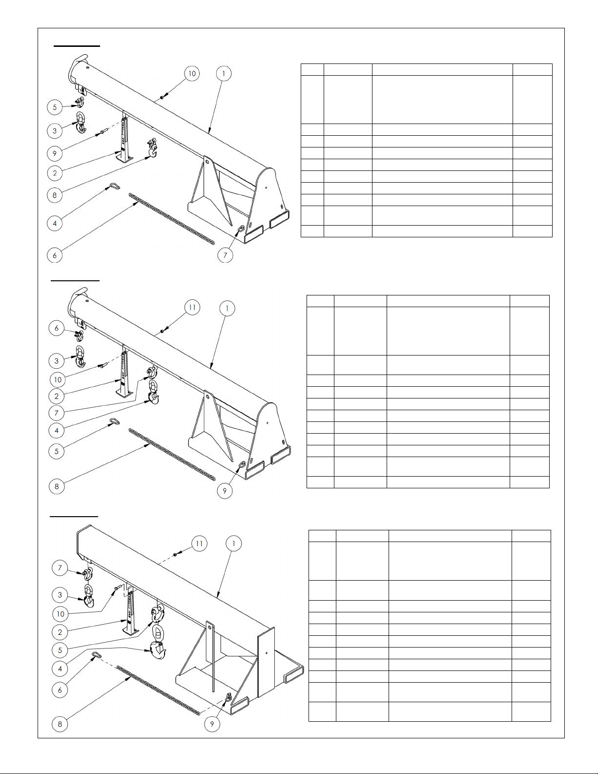
•Always make sure that shackle pins (see shackles in exploded views on pages 3-22) are secure before applying a
load to the load hook. Tighten the screw pin before each use.
•Before raising the boom from the floor AND before attaching the load to the boom, tilt the fork lift mast away from
the boom to ensure that the boom will not slide towards the tips of the forks.
•ALWAYS follow the LOADING AND USING instructions that appear on p. 23-25. Failure to properly position a load
might cause a dangerous degree of load swing when the boom is elevated.
•Only use the boom to lift loads. DO NOT use the boom to drag items.
•Transport loads with the bottom of the load and the forks as low as possible.
•Drive suspended loads at low speed. Brake and turn slowly and cautiously.
•DO NOT modify the boom in any way. Modifications automatically void the LIMITED WARRANTY (p. 28) and might
make the boom unsafe to use.
NATIONAL STANDARDS
US OSHA Rule 1910.178 (29 CFR 1910.178; the “Rule”) classifies this device as a (lift truck) front end attachment
whenever it is mounted on a lift truck. The Rule incorporates American National Standard ANSI/ITSDF B56.1 (the
“Standard”). The Standard is published by the Industrial Truck Standards Development Foundation on its website
(www.itsdf.org) were it is freely downloadable at http://www.itsdf.org/cue/b56-standards.html. Before putting this
device into service, you must acquire a copy of the Standard. Apply all relevant parts of Part II: For the User. If
instructions provided in this manual conflict with the Standard, then you should apply the instructions in the Standard.
Vestil requests that you immediately share any such conflicts with its TECHNICAL SERVICE personnel. Contact
information for TECHNICAL SERVICE appears on the cover page of this manual.
01/11 rev. 6/11/2020 LM MANUAL
Copyright 2016 Vestil Manufacturing Co. Page 3of 28
FIG. 1A: LM-1T-3-24 & LM-1T-4k Exploded View & Bill of Materials
Item
Part No.
Description
Quantity
1
08-514-176
08-514-111
08-514-177
08-514-178
Weldment, frame, boom/base, 4k:
LM-1T-4-11
LM-1T-4-24 & LM-1T-3-24
LM-1T-4-30
LM-1T-4-36
1
1
1
1
2 08-514-261 Weldment, inner tube 1
3
08-014-134
Frame, front support leg casting
1
4 08-025-004 X-handle, locking bolt 1
5 08-145-001 Swivel hook, 2-ton 1
6
08-145-041
5/
16
” snap hook
1
7 08-145-010
1
/2” shackle, 2-ton 1
8
99-145-037
5/
16
” chain 36” long
1
9 99-145-084 Lap link 1
10
99-645-019
2-ton hook and shackle
1
11 11211
1/
2
” -13UNC x 2” HHCS zinc-plated
bolt
1
12 36109
1
/2” – 13UNC hex nut 1
FIG. 1B: LM-1T-6k Exploded View & Bill of Materials
FIG. 1C: LM-1T-8k Exploded View & Bill of Materials
Item
Part No.
Description
Quantity
1
08-514-179
08-514-113
08-514-180
08-514-181
Weldment, frame, boom/base, 6k:
LM-1T-6-11
LM-1T-6-24
LM-1T-6-30
LM-1T-6-36
1
1
1
1
2
08-514-261
Weldment, inner tube
1
3
08-014-134
Frame, front support leg casting
1
4
08-025-004
X-handle, locking bolt
1
5
08-145-001
Swivel hook, 2-ton
1
6
08-145-002
Swivel hook, 3-ton
1
7
08-145-041
5/16” snap hook
1
8
08-145-010
1/2” shackle, 2-ton
1
9
99-145-019
5/8” 3.25-ton shackle
1
10
99-145-037
5/16” chain 36” long
1
11
99-145-084
Lap link
1
12 11211
1/
2
” -13UNC x 2” HHCS zinc-plated
bolt
1
13
36109
1/2” – 13UNC hex nut
1
Item
Part No.
Description
Quantity
1 08-514-115
08-514-315
08-514-316
Weldment, frame, boom/base, 8k:
LM-1T-8-24
LM-1T-8-30
LM-1T-8-36
1
1
1
2
08-514-272
Weldment, inner tube
1
3
08-014-134
Frame, front support leg casting
1
4
08-025-004
X-handle, locking bolt
1
5
08-145-002
Swivel hook, 3-ton
1
6
08-145-005
Swivel hook, 5-ton
1
7
08-145-006
7/8” 6.5-ton shackle
1
8
08-145-041
5/16” snap hook
1
9
99-145-019
5/8” 3.25-ton shackle
1
10
99-145-037
5/16” chain 36” long
1
11
99-145-084
Lap link
1
12 11211
1/
2
” -13UNC x 2” HHCS zinc-
plated bolt
1
13
36110
1/2” – 13UNC zinc-plated hex nut
1
Table of Contents Rev. 6/11/2020 LM, MANUAL
Table of Contents Copyright 2020 Vestil Manufacturing Co. Page 4 of 28
FIG. 1D: LM-1T- 4k, 6k & 8k Centers of Gravity and Maximum Load Ratings for
Varying Load Attachment Point and Boom Extension Combinations
The center of gravity of the boom changes as boom length changes. As shown in the diagram below, the
horizontal center of gravity may be located at any point from RHCG to EHCG:
•Retracted horizontal center of gravity (RHCG): boom fully retracted and unloaded. RHCG is measured from
the “origin point” of the above diagram (edges of the fork pockets);
•Extended horizontal center of gravity (EHCG): boom fully extended and unloaded. EHCG is also measured
from the “origin point” of the above diagram (edges of the fork pockets);
•All other combinations of boom extension and load position produce a horizontal center of gravity located
somewhere between RHCG and EHCG.
Model Extended horizontal
center of gravity
Retracted horizontal
center of gravity
Vertical center of
gravity A B C D E F G Net
weight
LM-1T-3-24 4813/16” (124 cm) 3211/16 (83 cm) 1313/16” (33.5 cm) 86-1511/4”13” 32” 24” 257/8” 71/2
”
21/2
”
434.4 lb.
LM-1T-4-11 51 in. (129.5 cm) 33
15
/16 in. (86.2 cm) 13
5
/8” (34.6 cm) 86-153
1
/2”13” 19” 11” 25
7
/8” 7
1
/2
”
2
1
/2
”
404.7 lb.
LM-1T-4-24 48
13
/16 in. (124.0 cm)
32
11
/16 in. (83.0 cm) 13
3
/16
” (33.5 cm)
86-153
1
/2”13” 32” 24” 25
7
/8” 7
1
/2
”
2
1
/2
”
429.3 lb.
LM-1T-4-30 47
7
/16 in. (120.5 cm) 32 in. (81.3 cm) 12
15
/16” (32.9 cm) 86-153
1
/2”13” 38” 30” 25
7
/8” 7
1
/2
”
2
1
/2
”
447.4 lb.
LM-1T-4-36 463/16 in. (117.3 cm) 315/16 in. (79.5 cm) 1211/16” (32.2 cm) 86-1531/2”13” 44” 36” 257/8” 71/2
”
21/2
”
465.4 lb.
LM-1T-6-11 47
7
/16 in. (120.5 cm) 32
3
/16 in. (81.8 cm) 12
5
/8” (32.1 cm) 86-153
1
/2”13” 19” 11” 25
7
/8” 7
1
/4
”
2
1
/4
”
452.7 lb.
LM-1T-6-24 45
11
/16 in. (116 cm) 31
3
/16 in. (79.2 cm) 12
5
/16” (31.3 cm) 86-153
1
/2”13” 32” 24” 25
7
/8” 7
1
/4
”
2
1
/4
”
477.4 lb.
LM-1T-6-30 44
1
/2in. (113 cm) 30
9
/16 in. (77.6 cm) 12
1
/8” (30.8 cm) 86-153
1
/2”13” 38” 30” 25
7
/8” 7
1
/4
”
2
1
/4
”
497.0 lb.
LM-1T-6-36 43
3
/8in. (110.2 cm) 29
15
/16 in. (76 cm) 11
15
/16” (30.3 cm) 86-153
1
/2”13” 44” 36” 25
7
/8” 7
1
/4
”
2
1
/4
”
516.5 lb.
LM-1T-8-24 531/4in. (135.3 cm) 347/16 in. (87.5 cm) 135/8” (34.6 cm) 845/8-1491/8”
111/2” 32” 24” 269/16”
71/4
”
21/4
”
665.3 lb.
LM-1T-8-30 53
1
/4in. (135.3 cm) 34
7
/16 in. (87.5 cm) 13
5
/8” (34.6 cm) 84
5
/8-149
1
/8”
11
1
/2” 38” 30” 26
9
/16”
7
1
/4
”
2
1
/4
”
688.5 lb.
LM-1T-8-36 53
1
/4in. (135.3 cm) 34
7
/16 in. (87.5 cm) 13
5
/8” (34.6 cm) 84
5
/8-149
1
/8”
11
1
/2” 44” 36” 26
9
/16”
7
1
/4
”
2
1
/4
”
711.7 lb.
Hook position
A
B
C
D
E
F
G
H
I
J
Distance from end of
boom
36”
91 cm
48”
122 cm
60”
152 cm
72”
183 cm
84”
213 cm
96”
244 cm
108”
274 cm
120”
305 cm
132”
335 cm
144”
366 cm
Maximum rated load. Load suspended from a single hook located at the corresponding hook position.
LM-1T-3-24
3000 lb.
1363 kg
2750 lb.
1250 kg
2500 lb.
1136 kg
2250 lb.
1022 kg
2000 lb.
909 kg
1750 lb.
795 kg
1500 lb.
681 kg
1250 lb.
568 kg
1000 lb.
454 kg
750 lb.
340 kg
LM-1T-4k
4000 lb.
1820 kg
3750 lb.
1705 kg
3500 lb.
1590 kg
3250 lb.
1477 kg
3000 lb.
1363 kg
2750 lb.
1250 kg
2500 lb.
1136 kg
2250 lb.
1022 kg
2000 lb.
909 kg
1750 lb.
795 kg
LM-1T-6k
6000 lb.
2727 kg
5000 lb.
2272 kg
4500 lb.
2045 kg
4000 lb.
1820 kg
3500 lb.
1590 kg
3000 lb.
1363 kg
2600 lb.
1181 kg
2300 lb.
1045 kg
2000 lb.
909 kg
1800 lb.
818 kg
LM-1T-8k
8000 lb.
3636 kg
6650 lb.
3022 kg
6000 lb.
2727 kg
5300 lb.
2409 kg
4650 lb.
2113 kg
4000 lb.
1820 kg
3500 lb.
1590 kg
3000 lb.
1363 kg
2600 lb.
1181 kg
2200 lb.
1000 kg
J I H G F E D C B A
= Center of gravity
FIG. 1E: LM-1T centers of gravity and dimensions
Table of Contents Rev. 6/11/2020 LM, MANUAL
Table of Contents Copyright 2020 Vestil Manufacturing Co. Page 5 of 28
FIG. 1F: LM-1NT-4k Exploded View & Bill of Materials
Item
Part No.
Description
Quantity
1
08-514-319
08-514-128
08-514-320
08-514-321
Weldment, frame, boom/base:
LM-1NT-4-11
LM-1NT-4-24
LM-1NT-4-30
LM-1NT-4-36
1
1
1
1
2
08-014-134
Frame, front support leg casting
1
3
08-145-001
Swivel hook, 2-ton
1
4
08-145-041
5/16” snap hook
1
5
08-145-010
1/2” 2-ton shackle
1
6
99-145-037
5/16” chain 36” long
1
7
99-145-084
Lap link
1
8
99-645-019
2-ton hook and shackle
1
9 11211
1/
2
in. – 13 UNC x 2in. HHCS zinc-
plated bolt
1
10
36109
1/2in. – 13 UNC hex nut
1
FIG. 1G: LM-1NT-6k Exploded View & Bill of Materials
Item
Part No.
Description
Quantity
1
08-514-322
08-514-129
08-514-323
08-514-324
Weldment, frame, boom/base:
LM-1NT-6-11
LM-1NT-6-24
LM-1NT-6-30
LM-1NT-6-36
1
1
1
1
2 08-014-134
Frame, front support leg
casting
1
3
08-145-001
Swivel hook, 2-ton
1
4
08-145-002
Swivel hook, 3-ton
1
5
08-145-041
5
/16” snap hook
1
6
08-145-010
1
/2” 2-ton shackle
1
7
99-145-019
5/8” 3.25-ton shackle
1
8
99-145-037
5
/16” chain 36” long
1
9
99-145-084
Lap link
1
10 11211
1/
2
in. – 13 UNC x 2in. HHCS
zinc-plated bolt
1
11
36109
1/2in. – 13 UNC hex nut
1
FIG. 1H: LM-1NT-8k Exploded View & Bill of Materials
Item
Part No.
Description
Quantity
1 08-514-130
08-514-317
08-514-318
Weldment, frame, boom/base:
LM-1NT-8-24
LM-1NT-8-30
LM-1NT-8-36
1
1
1
2 08-014-134
Frame, front support leg
casting
1
3
08-145-002
Swivel hook, 3-ton
1
4
08-145-005
Swivel hook, 5-ton
1
5
08-145-006
7/8” 6.5-ton shackle
1
6
08-145-041
5
/16” snap hook
1
7
99-145-019
5/8” 3.25-ton shackle
1
8
99-145-037
5
/16” chain 36” long
1
9
99-145-084
Lap link
1
10 11211
1/
2
in. – 13 UNC x 2in. HHCS
zinc-plated bolt
1
11 36110
1/
2
” – 13UNC zinc-plated hex
nut
1

Other manuals for LM-Series

1

This manual suits for next models

11

Other Vestil Truck manuals

Vestil CARPET-45 User manual

Vestil

Vestil CARPET-45 User manual

Vestil ALL-T-2-GPT User manual

Vestil

Vestil ALL-T-2-GPT User manual

Vestil PM2-3344-SLP User manual

Vestil

Vestil PM2-3344-SLP User manual

Vestil CARPET-D User manual

Vestil

Vestil CARPET-D User manual

Vestil EPT Series User manual

Vestil

Vestil EPT Series User manual

Vestil EPT Series User manual

Vestil

Vestil EPT Series User manual

Vestil PM4-LP Series User manual

Vestil

Vestil PM4-LP Series User manual

Vestil EPT-2745-45 User manual

Vestil

Vestil EPT-2745-45 User manual

Vestil AWST-3672-PU User manual

Vestil

Vestil AWST-3672-PU User manual

Popular Truck manuals by other brands

SAC TURBO-MAX 6046 Operator's manual

SAC

SAC TURBO-MAX 6046 Operator's manual

Sealey CST801 quick start guide

Sealey

Sealey CST801 quick start guide

RAM 1500 2019 owner's manual

RAM

RAM 1500 2019 owner's manual

BT Ergomover 620 AC-TT Operator's manual

BT

BT Ergomover 620 AC-TT Operator's manual

Still EXU-16 Original instructions

Still

Still EXU-16 Original instructions

Lift-Rite Titan Series Owner's Manual, Operating  Instructions Manual, and  Replacement Parts Manual

Lift-Rite

Lift-Rite Titan Series Owner's Manual, Operating Instructions Manual, and Replacement Parts Manual

Noblelift PS E12BSL Instruction handbook

Noblelift

Noblelift PS E12BSL Instruction handbook

Noblelift PTE12N Instruction handbook

Noblelift

Noblelift PTE12N Instruction handbook

Noblelift PT20H Instruction handbook

Noblelift

Noblelift PT20H Instruction handbook

Daewoo Novus M2SEF manual

Daewoo

Daewoo Novus M2SEF manual

Dawson Truck Mate Operator's manual

Dawson

Dawson Truck Mate Operator's manual

Super Products Camel 1200 (Ejector Unloading) Operator's manual

Super Products

Super Products Camel 1200 (Ejector Unloading) Operator's manual

Taylor-Dunn TT-316 36AC Operator's manual

Taylor-Dunn

Taylor-Dunn TT-316 36AC Operator's manual

Komatsu HM350-2 brochure

Komatsu

Komatsu HM350-2 brochure

Versalift TEL-29-N Operator's manual

Versalift

Versalift TEL-29-N Operator's manual

UralAZ URAL-4320-02 Service manual

UralAZ

UralAZ URAL-4320-02 Service manual

Komatsu 530M Operation & maintenance manual

Komatsu

Komatsu 530M Operation & maintenance manual

jcb 506-23 Operator's manual

jcb

jcb 506-23 Operator's manual

manuals.online logo
manuals.online logoBrands
  • About & Mission
  • Contact us
  • Privacy Policy
  • Terms and Conditions

Copyright 2025 Manuals.Online. All Rights Reserved.