Vetter VCB C.Tec Quick guide

Article No. 9987072900 | © Vetter GmbH I 07/23 I Changes and errors excepted.
Emergency Pneumatics.
Translation of the
Original Operating Instructions
Vetter Connectable Bags
VCB and VCB N C.Tec 12 bar (174 psi)
Keep in a safe place for future use!

VCB and VCB N C.Tec Bags 12 bar (174 psi)
Page 1/22
Contents
1. Important preliminary remarks ....................................2
2. Product description ...............................................2
2.1 Description of the set .......................................2
2.2 Other accessories ...........................................5
2.3 Vetter safety coupling system ...............................6
2.4 Product description.........................................7
2.5 Correct usage.............................................11
2.6 Safety instructions ........................................11
3. Preparing the product for use ...................................14
3.1 Preparations for operation ................................ 14
3.2 Connecting the bags...................................... 14
3.3 Application instructions...................................15
4. Operating instructions .......................................... 15
4.1 Operation with compressed bottles .......................15
4.2 Operation with other sources of compressed air ...........16
4.3 Dismantling of the lifting bag system after use.............17
4.4 Limit for the period of use................................. 17
4.5 Care, maintenance........................................17
5. Elimination of defects ...........................................17
6. Storage.........................................................18
7. Repetitive tests .................................................19
8. Diagram: Force vs. Stroke (available on request).................. 19
9. Technical data ..................................................20
EC Conformity Declaration (available on request) ...................21

Page 2/22
1. Important preliminary remarks
Only the knowledge and exact observance of these operating in-
structions guarantees correct and professional operation, produ-
ces the greatest possible use and ensures any claims made within
the scope of the Vetter guarantee.
The handling of the Vetter VCB C.Tec (Vetter Connectable Bags -
Connectable Technology) is only to be made by trained persons
using the operating instructions of the manufacturer and the in-
formation from the user.
In addition to the operating instructions, all national, generally
applicable, statutory and other binding accident prevention re-
gulations must be observed and instructed.
The disposal of discarded lifting bags is to be carried out accor-
ding to disposal regulations valid for the region.
The operating instructions given here are to be regarded as part
of the product and are to be kept for the complete life duration of
the product. In case the product should be passed on to a succes-
sive user then the operating instructions must also be included.
2. Product description
2.1 Description of the set
a. C.Tec Bag 12 bar (174 psi)
The selection of bag size must correspond to operation requi-
rements. There are 3 sizes available from 30 t, 75 t and 172 t.
b. Connecting pins
By using the connecting pins, all bag sizes of the C.Tec series can
be connected to each other to form a lifting system comprising
max. three bags.
This pin has been designed so that the bags can only be connec-
ted from one position. This ensures that the hose connections of
the individual bags are always perpendicular to each other and
that no hoses are unintentionally under the load. This increases
the safety factor for the operator many times over, see chapter 3.2.
c. Ination hoses
In order to inate C.Tec Bags 12 bar from a safe position for the
operator, there are ination hoses available with lengths of 5 m
and 10 m. The hose colours are used exclusively to assist the ope-
rator in recognizing the correct side when controlling the C.Tec
Bags 12 bar.

VCB and VCB N C.Tec Bags 12 bar (174 psi)
Page 3/22
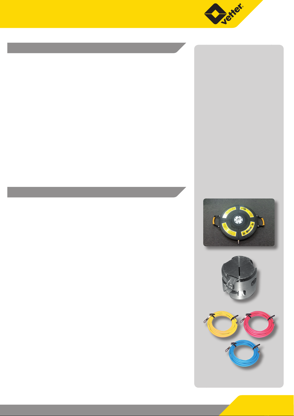
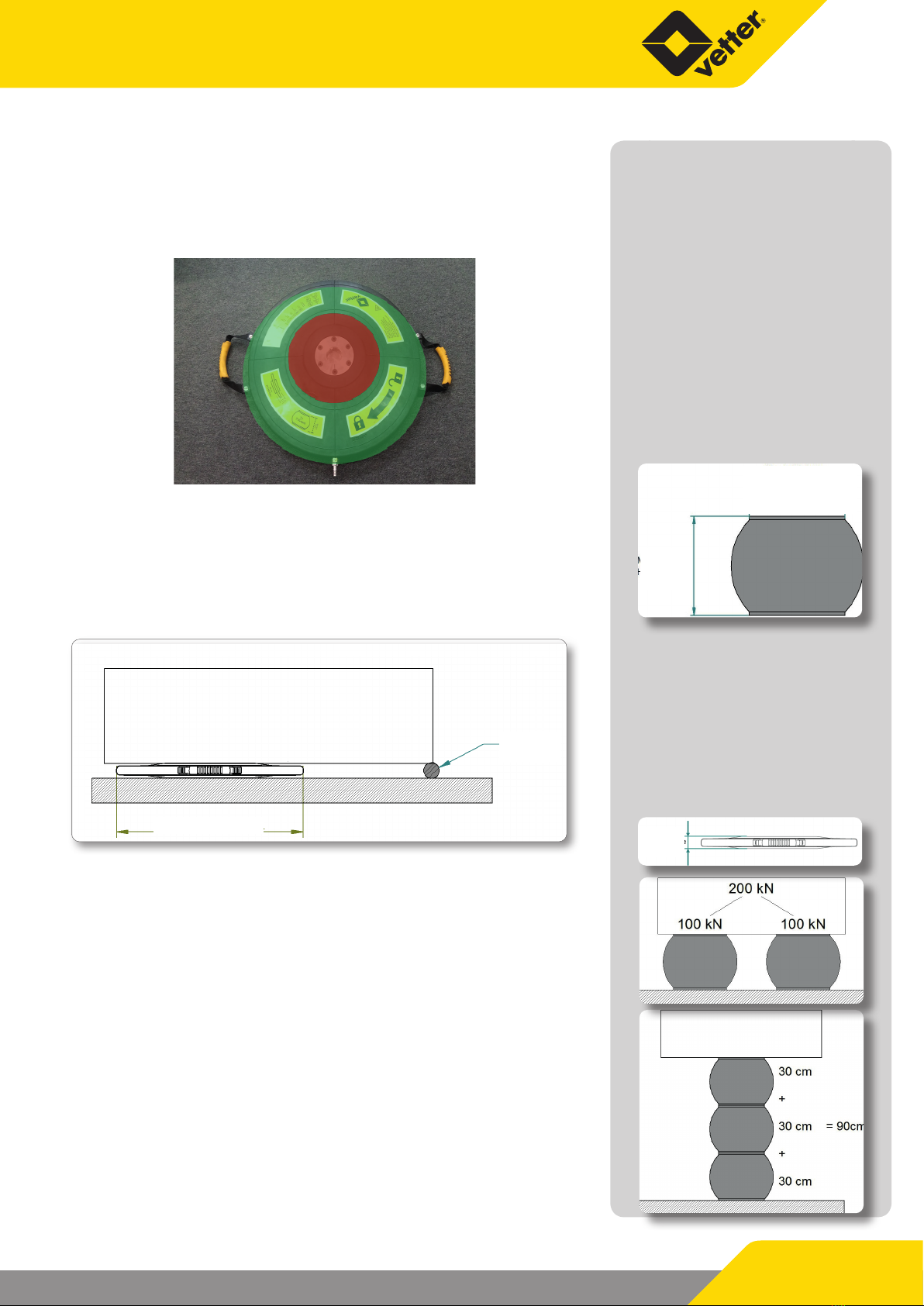
d. Controller 12 bar
When lling and deating of the bags, the
manometer and the load must be observed.
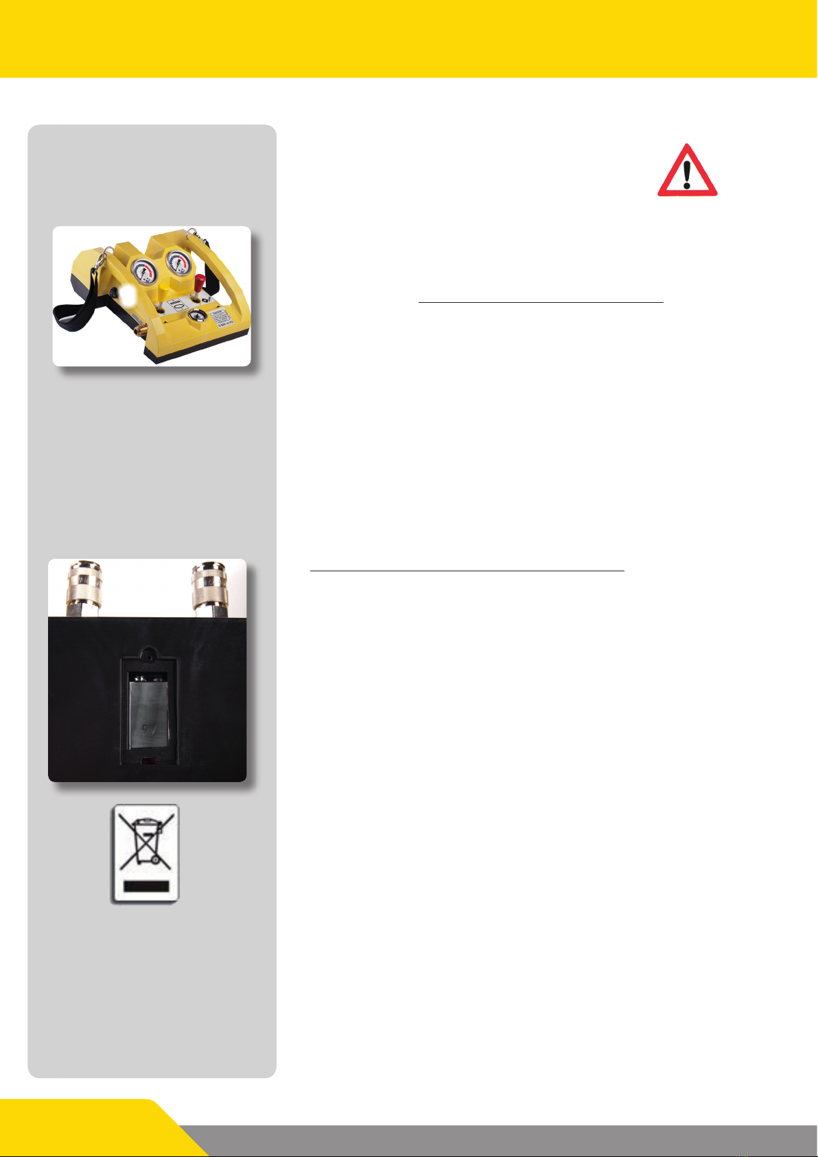
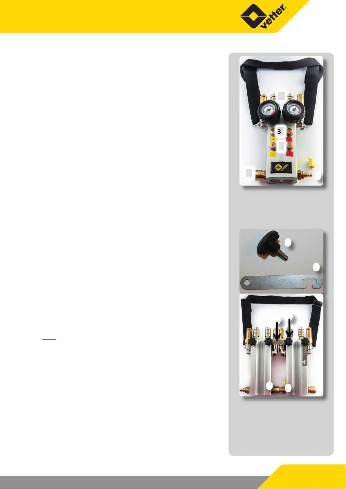
Air CU (Control Unit) 12 bar deadman
Connect the ination hoses on the output couplings on the rear
side of the controller. Connect the air suppply to the input coup-
ling on the side. Move the switching lever towards you in order
to inate the C.Tec Bag. In doing this, observe the corresponding
manometer and the movement of the load. When the required
operating pressure for the lifting power or lift height is reached,
terminate the ination sequence by releasing the lever. Latest
when the safety valve blows o or the red marking is reached!
The switching lever automatically returns back to the zero posi-
tion (dead-man switching). The integrated safety valve activates
automatically as soon as the maximum operating pressure of 12
bar is exceeded when inating or when there is a sudden increase
in bag pressure caused by an unintended loading of the bag.
The activation tolerance for opening and closing of the
safety valve must only be a maximum of +/- 10%.
Press the switching lever in the opposite direction in order to de-
ate the bag or to lower the load.
The lighting of the control element illuminates all couplings,
switch levers and manometers. It is switched on and o with
switch (1) on the side.
The control element is supplied by a 9 V block battery. Since the
entire lifting bag system is designed for a temperature range of
-20 °C to +55 °C, only batteries with this temperature range are
allowed to be used. Based on the current state of the art, only li-
thium batteries meet this requirement.
To insert the battery, unscrew the battery compartment, replace
the old battery with a new one and screw the battery compart-
ment back together.
Control elements with lighting come under the German Law on
electrical and electronic devices (ElektroG) of 24 March 2005 for
implementation of the EC Directive 2002/96/EC on electrical and
electronic waste – WEEE Directive.
The label attached to the battery compartment cover points
out that the electronic components in this product must not be
handled as domestic waste; they have to be returned to the ma-
nufacturer (return freight paid) for recycling.
1
Dierent couplings!

Page 4/22
Dual deadman controller 12 bar / 174 psi,
aluminium style, connectable
Connect the lling hose to the outlet couplings (4) on the rear of
the control element. Connect the air supply to the lateral inlet cou-
pling (1). To ll the VCB C.Tec Bags press the lower“+”push-button
(2). When the desired operating pressure has been reached for the
lift force or lift height, discontinue the lling process by releasing
the push-button. Release latest when the safety valve blows o
or the red marking has been reached! During this process, the
push-button independently returns to the zero setting (deadman
switch). If you overll the bags past the maximum operating pres-
sure of 12 bar or if there is an unexpected additional load on the
bag, the integrated safety valve automatically blows o.
The activation tolerance for opening and closing of the
safety valve must only be a maximum of +/- 10 %.
To drain the bag or lower the load, press the upper“-”push-button
(3).
To prevent long-term damage of the membranes in the interior,
vent the control element after use. To vent, rst press all push-
buttons (+ / -) one time.
Connecting and disconnecting two double control elements
To link, connect the nipple (5) of the left control element with the
inlet coupling (1) of the next control element. Swivel the transom
(7) on the rear of the right control element to the side of the left
control element and screw it tight with the star screws (6).
The control elements are now connected and will be supplied
with compressed air through the inlet coupling of the left control
element.
Before separating, disconnect the air supply connection and de-
pressurise the control element by pressing the push-buttons.
Note:
Do not separate the control elements as long as the bags are con-
nected.
Loosen the star screws on the rear and swivel the transom back
into place. Press both control elements together, pull back the
union nut of the inlet coupling of the right control element and
then let go of both control elements. The control elements are
now disconnected.
If the transom and the star screws are not going to remain on the
control element, keep them together in a bag.
4
3
2
15
6
7
5
6
7
1

Protective cap VCB N
Protective cap VCB
VCB and VCB N C.Tec Bags 12 bar (174 psi)
Page 5/22
e. Protective cap
To protect the load plate and the adhesive rubber
against damage, the Vetter protective cap must be
used every time the C.Tec lifting bags are used.
The protective cap also increases the friction
between the load plate and the ground or the
load plate and the load to be lifted. This reduces
the risk of the lifting bag being thrown out and
the load plate and the adhesive rubber being damaged.
Inventory check
On acceptance of the C.Tec Bag equipment a check is to be made to see if
the delivery is complete according to the delivery note. In addition to this
a visual check and function test is to be made according to the operating
instructions.
2.2 Other accessories
Pos. Artikel-Nr. Bezeichnung
1
1600034000
or
1600032000
Pressure regulator 200/300
bar
US Version 4500 psi
(not compatible with below
mentioned compressed air
bottles)
21600010800 Comp. air bottle 6 l / 300 bar
31600019900 Comp. air bottle 9 l / 300 bar
41600009100 Dual connector 300 bar
51600014500 Pressure regulator
61600012000 Adapter for construction site
compressor

Page 6/22
71200008800 Connecting pin VCB N
81000012500 Valise VCB N 30
91000012600 Valise VCB N 75
10 1000012700 Valise VCB 172
11 1200009700 Protective cap VCB N 30
12 1200009800 Protective cap VCB N 75
13 1000012700 Protective cap VCB 172
2.3 Vetter safety coupling system
The S.Tec and C.Tec series are provided with the same coupling system.
That means Vetter 12 bar accessories can be used for both bag series.
a. Input coupling of the controller
Connect the air supply hose or the connection hose of the pressure re-
gulator to the nipple of the input coupling (1) on the controller pushing
the nipple solidly into the coupling until the ratchet action can be felt. In
order to ensure that it is correctly connected: turn the brass sleeve (2) of
the coupling opposite to the safety pin (3).
b. Couplings of the ination hose
To connect the ination hoses to the corresponding controller or to the
C.Tec Bag, press the hoses or bag nipple solidly into the coupling until
the ratchet action can be felt.The coupling sleeve must be seated on the
support ring without any gap (1). To release the connection (only in the
pressure-free condition) the nipple must be solidly pressed against the
spring pressure in the coupling. At the same time the coupling sleeve
must be pushed back. The coupling then releases.
1
2
3
1

VCB and VCB N C.Tec Bags 12 bar (174 psi)
Page 7/22
c. Ination with an 8 bar or 10 bar ination device
The C.Tec 12 safety coupling system facilitates lling the pad with
the Vetter 8 bar or 10 bar system. However, do this only in excep-
tional cases since in such a case the pad cannot lift with its entire
lifting force.
2.4 Product description
VCB C.Tec Bags are made by hand from high quality raw materials
so that after completion, a seamless bag is produced. The semi-
nished product is vulcanized under the inuence of pressure
and temperature and by doing this the individual layers bond to
form an elastomer body. After production has been nalized, each
C.Tec Bag is subjected to a plant acceptance test within the scope
of quality assurance.
Material of the C.Tec Bag: CR/Aramide, hot vulcanized
Small folds form in the edge area during the lling pro-
cess. That is attributable to the setup and the design but
does not impair the functioning. They disappear as the
pressure builds up to the permissible operating pressu-
re.
Temperature resistance of C.Tec Bags:
Cold resistance -40 °C
Cold exible -20 °C
Heat resistance long-term +55 °C
Heat resistance short-term +70 °C
The aramid reinforcement of the C.Tec bags
can be damaged if the surface of the bag is
damaged by cuts, cracks or puncturing and
by the exposure to ozone and sunlight.
Perform a visual inspection after each use. Pay particular attention
to the following damage:
9Damage by separation
9Damage by cuts
9Damage by punctures
9Damage by heat and chemicals
Danger of bursting! If, when carrying out
the check, this type of damage is
determined then the bag is to be
immediately taken out of service.
Repair is not possible.

Page 8/22
During the lifting process, at least 2/3 (red area) must be fully inserted
under the load. In order to use the theoretical maximum lifting force, the
entire eective area (red + green area) must be fully underneath the load
to be lifted and pressure must be applied to the lifting bag with the max.
permissible operating pressure.
With increasing height, the lifting bags takes on a attened spherical
shape; under certain circumstances the load will rotate around a pivot
point due to a one-sided lifting process. That reduces the contact area
to the load up to the predened nal lifting force at a dened lift height.
The lifting bag only reaches the greatest possible lifting height in the
unloaded state.
Pay attention to the insertion height before use. Under certain circum-
stances, the load rst has to be lifted with a at lifting bag until there is a
suciently large opening.
In case the lifting power produced by the C.Tec Bag is not sucient, de-
pending on the lift height, then a number of C.Tec Bags can be placed
next to each other. The lifting capacity doubles.
In case the lifting height is not sucient when using only one C.Tec bag,
a maximum of 3 bags can be connected to form a lifting system using
the connecting pins when the load is non-slip. In this application, the
respective lifting heights of the C.Tec bags used add up. However, the
lifting force corresponds only with that of the smaller bag.
Eective area
Pivot
Maximum
lift height
Insertion
height

VCB and VCB N C.Tec Bags 12 bar (174 psi)
Page 9/22
For safety-engineering reasons however only the
following combinations can be braced into a lifting
system:
Combination 1 Combination 2 Combination 3
Max. three bags of
the same size
One small bag on two
bags of the same size
One VCB N 30 on two
VCB N 75‘s,
one VCB N 75 on two
VCB 172‘s
Three bags of
dierent sizes
The stack is built up
from the largest bag
at the bottom to the
smallest at the top.
Combination 1 provides the greatest safety and stability and
should be preferred over Combination 2 and 3. Combination 2
is preferable to Combination 3!
Never use the following combinations:
Combination 1 Combination 2 Combination 3
A smaller bag un-
der a larger bag
A lifting bag system
made of more than
three bags
Two bags of the
same size on one
larger bag
The user must be aware of these combinations.
They must be taken into account during
deployment!

Page 10/22
If the rendered lifting height of a stack of C.Tec bags is not sucient de-
pending on the double or triple lifting height, it is possible to place two
lifting systems next to each other:
Never position 4 or more bags on top of each
other!
An C.Tec Bag under load can be compared to a spring under tension
with respect to its behavour. As soon as the C.Tec Bag is suddenly re-
leased, e.g. by slipping, load break or anything similar then there will be
spontaneous catapulting outwards of the C.Tec Bag.
Never stand in front of the C.Tec Bag!
This is an area of danger!
When lling the bags of a lifting system, always comply with the fol-
lowing sequence:
1. Fill the top bag to 5 bar
2. Fill the centre bag to 5 bar
3. Fill the bottom bag to 5 bar
You can then increase the operating pressure to the max. as desired.
However, since the top bag adapts to the load on the contour, this bag
must always have the highest pressure.
Evacuate in the reverse sequence.
1. Completely evacuate the bottom bag
2. Completely evacuate the centre bag
3. Completely evacuate the top bag
The Aramid installed in the bag only forms a
xed bre level at approx. 5 bar. For that reason,
even if using another lling technique, always ll
the bag to at least 5 bar before lling the next bag.

VCB and VCB N C.Tec Bags 12 bar (174 psi)
Page 11/22
2.5 Correct usage
Above all, C.Tec bags are a pneumatically-driven rescue device that can
be connected into a lifting system for the rescue services (e.g. re briga-
de) and can be used to free trapped persons, create escape and access
routes and undertake similar measures. Furthermore, the C.Tec bags
can also be used as work equipment for lifting or moving loads. Lifting
heights of up to 2 m can be reached by connecting the bags into a lifting
system.
C.Tec bags in the re-ghting sector underlie the national requirements,
DIN EN 13731. Further instruction information can be obtained from the
operating instructions of the user. The complete S.Tec system is cold-
resistant to -20 °C and heat-resistant up to +55 °C.
2.6 Safety instructions
Pre-specied personal protective clothing is to be worn during operati-
on! For example: protective clothing, safety footwear, helmet, protective
gloves, protection for eyes and face, noise protection etc.
The national regulations in connection with lifting bag systems and their
use are to be observed. For example: DIN EN 13731, national regulations.
The C.Tec Bags are only to be used with compressed air, under no cir-
cumstances are they to be used with inammable gases or aggressively
acting gases. VCB C.Tec Bags are only to be inated with original Vetter
C.Tec ination ttings because these were subjected to an acceptance
test by the manufacturer. The lifting bag system is to be tested for per-
fect condition before and after use (specications from the manufactu-
rer, national regulations).
The national safety guidelines must be observed and adhered to world-
wide.
In the Federal Republic of Germany, for example, regular safety inspec-
tions are prescribed by DGUV Principle 305-002.
Continuously shore up the lifted load with friction while the lifting pro-
cess is progressing, secure it against slipping away and, e.g., stabilise
with supports.The stable condition of foundation support material must
always be observed during construction of the foundation support. Use
only materials that are suitable for the load to be lifted such as shoring
sets made of wood or plastic or wooden beams, etc. While doing so, be
sure to comply with the max. permitted load bearing capacity of the ma-
terials.
In order to fully use the strengths of the S.Tec Bag, the distance between
load and bag should be at a minimum.
The foundation support must brace at least the
complete area of the bag and the smallest edge
length of the foundation support must be larger
than the height of the foundation support.
Metal must never be place on metal!
Attention: danger of slipping!
Load

Page 12/22
In case of slippery ground (ice, snow, clay, etc.) or coarse gravel, place
the Vetter protective cap or other anti-slip materials under the bag to
increase the ground adhesion.
Point-shaped loads are to be avoided, e.g. construction claws or screws.
Never place the bags on sharp edges, hot or red hot components. Use
suitable temporary storages and cover the complete contact area of the
bag. Protect the bag against ying sparks during welding or separation
work. Do not additionally load bags with such things as hydraulic lifting
devices, winches or falling loads.
Never remain beneath a lifted load, never hold
the load from below!
Remain at a distance!
Avoid shearing eects by squeezing of the bag when lowering the load!
During operation never stand in front of the bag
but always to one side, because the bag could
catapult outwards under unfavourable
conditions!
Additional instruction:
Limit the number of persons in the hazardous
area to a minimum. People who are not involved
must stay outside of the hazardous area. Also
provide sucient clearance to the load to be
lifted and to the debris area.
Monitor the load during the entire lifting process
and, if necessary, abort and correct as dictated by
the circumstances.
Aborting the lifting process:
1. Secure the load
2. Evacuate the bag
3. Reposition the bag
Make sure that
9there are no malfunctions
9the bags do not move out of the centre of gravity of the load
Centre of gravity of the load Centre of gravity of the load

VCB and VCB N C.Tec Bags 12 bar (174 psi)
Page 13/22
9the max. tilt angle is not exceeded
Angle α must never exceed 45°. Otherwise, the
bags could be ung out!
9the top head plate cannot move out of the stroke centre which is de-
ned by the bottom plate; otherwise the bags could uncontrollably
ing out
A C.Tec Bag can burst under adverse conditions with incorrect opera-
tion, incorrect handling or by manipulation on the controller and/or
ination hose (problems concerning pressure waves and sound waves,
uncontrolled movement)!
Vetter C.Tec Bags are not suited for use in
explosion endangered zones!
Plate outside the stroke centre
Pivot
Pivot
Pivot
Stroke centre
Stroke centre

Page 14/22
3. Preparing the product for use
3.1 Preparations for operation
Remove a set of C.Tec bags from the vehicle and perform a visual inspection. Prepare the ination device. Ensure
that sucient air supply is available.
Only perfectly working and tested S.Tec Bag systems are to be used!
Since there is no standard set, in the scope of his responsibility the respective commanding ocer decides on
the deployment method while following the standard deployment rules and the operating organisation‘s ope-
rational directives.
These operating instructions impart the basic handling of the bag system so they can only be used as the basis
for previously trained and correspondingly qualied personnel in action.
To reduce the hazards to a minimum and preventing accidents, the commanding ocer should make a short risk
assessment together with the operators before each use. This will create safety when handling the lifting bags
during use in the respective situation.
3.2 Connecting the bags
In order to be able to connect max. 3 bags with each other, a special bayonet system has been developed. This
allows 2 bags to be joined together without tools using a connecting pin, regardless of their size. At the same
time, the bags can only be joined in one position due to the arrangement or position of the nipples and grooves.
This ensures that the air connections are always vertical to each other in a lifting system.
Use a lifting system only if all valve connections are arranged vertically on top of each
other.
1. Insert the connecting pin into the lower bag so that the markings on the connecting plate and the connec-
ting pin are aligned. It does not matter which side of the connecting pin is used. The arrangement of the
nipples is the same on both sides. Now turn the pin clockwise or in the direction of the arrow until it makes
contact with the end stop and is locked in place.

VCB and VCB N C.Tec Bags 12 bar (174 psi)
Page 15/22
2. Then place the upper bag on the connecting pin already mounted.
The valve of the upper bag must be positioned vertically to the open
lock of the lower bag. The nipple of the connecting pin must be en-
gaged in the bag. Now turn the upper bag clockwise until the makes
contact with the end stop and the air connections of both bags are
vertical to each other.
To prevent the connection from loosening in use, the connection
parts are manufactured to t precisely. To make it easier to close or
open the connection, grasp both bags at the outer edge while tur-
ning the upper bag.
3.3 Application instructions
Push in the C.Tec bags at a suitable point completely under the load. Use
friction to continuously prop up, support and/or secure the lifted load
against slipping away while the lifting process progresses.
Never stand in front of the bag during operation but to the side of the
C.Tec Bag because it could be catapulted outwards under unfavourable
conditions.
4. Operating instructions
4.1 Operation with compressed bottles
When using connected lifting bags, keep a
sucient number of compressed-air bottles ready.
Connect the pressure reducer to the compressed air bottle 200 bar or
300 bar using the tommy screw (1). Close the hand wheel of the pressu-
re reducer (2). Open the valve on the bottle (3) slowly. The pre-pressure
manometer (4) indicates the pressure in the bottle.
Adjust the back pressure to approximately 14 bar with the regulation
bar (5) (indication of the reduced pressure on the back pressure mano-
meter (6)).
Connect the air hose of the pressure reducer via the nipple to the input
coupling (7) of the controller. In doing this, press the nipple into the cou-
pling until you feel it lock in. For additional safety: turn the brass sleeve
(8) so that it is opposite the safety pin (9).
Open the hand wheel (2) of the pressure reducer.
The lifting bag system is ready for operation.
7
8
9
2
1
34
5
6
Load

Page 16/22
4.2 Operation with other sources of compressed air
Basically, every source of air available can be used for operation of the
C.Tec Bags 12 bar as long as the pressure does not exceed 14 bar and that
the air is free of oil as far as possible. Amongst others, the set of transition
pieces (Art. No.: 1600 0125 01) with the following adapters are available for
operation with other air sources:
12
3
4
5
67
8
9
1. Truck compressed air connection, dual brake system.
For tapping air out of the trailer coupling head.
2. Dummy coupling
Seals o the control line of the brake system
Remember! Ensure that the truck does not roll, use brake blocks!
3. Truck tyre ination device adapter
For tapping o air from the so-called tyre ination bottle near the bra-
ke.
Remember! The tyre ination connection must be ensured by a
safety valve as a standard!
4. Truck tyre valve
Ination with a normal hand or foot pump as well as other air supplies
for tyre ination.
5. Truck tyre valve connection, can be clamped
For extracting air for the spare tyre.
6. Adapter for the local air pressure network.
7. Adapter Construction-site compressor
8. Air supply hose, 10 m, green, with blocking valve.
9. Case, red

VCB and VCB N C.Tec Bags 12 bar (174 psi)
Page 17/22
4.3 Dismantling of the lifting bag system after use
Dismantling of the lifting bag system is carried out after ensuring the lifted load and complete deation of the
lifting bag system, including dismantling of all accessory parts in the reverse order.
4.4 Limit for the period of use
Since there is no duty to discard lifting bags (as, e.g., there is for rescue cushions), we recommend discarding the
lifting bags at the latest after 18 years if they are deployed and stored properly and are regularly inspected.
4.5 Care, maintenance
The lifting bag equipment must be cleaned and checked for damage after each operation. Cleaning is normally
carried out with warm water and a detergent. Note that the connecting parts must always be free of contamina-
tion. Otherwise, when connecting the bags, the mechanism cannot engage completely and safe use is no longer
guaranteed. The grooves can be cleaned with a brush and blown free with compressed air.
Never clean with chemical cleansing agents and never clean with high-pressure
hot-water equipment.
Drying is to be made at normal room temperature.
A bag is to be immediately discarded if, during inspection, any sign of damage is established (refer to Page 7). It
is not possible to repair the bags. If the bolted plate, bolts or handles are damaged, replacement is possible but
solely by the manufacturer. However, sharp edges or notches can be machined with a le.
If needed, components such as manometers, safety valves and piston valves can be exchanged. Hose couplings
and nipples can also be exchanged.
After necessary repair, the equipment is to be checked according to the repetitive testes. This special test is also
to be documented.
To provide the best possible protection of the bags during long-term storage, comply with the following points
in DIN 7716.
9Evacuate the bags and store depressurised
9Horizontal storage in the Vetter packing bag
9Avoid direct solar radiation and air that contains ozone
9A low-dust and moderately ventilated environment is recommended
9Temperature between +15 °C and 25 °C and relative humidity < 65 %
Never suspend the bags by the carrying handles for storage!
The VETTER Guarantee is 2 years for C.Tec Bags.
5. Elimination of defects
If the safety valve blows too early because of foreign body penetration caught up inside then the blow-o valve
is to be fully opened on the head of safety valve by turning counter-clockwise so that the compressed air can
escape. If the foreign body is not removed, the safety valve must be replaced.
Then check to make certain that it functions perfectly.
If it is not possible to connect the C.Tec bags, remove any contamination from the connecting parts. If there is
minor damage to the metal parts, have the plate/pins replaced by the manufacturer.

Page 18/22
If the seal or the seal plate on the safety valve of the controller on the upper part of
the valve has been removed then correct operation is no longer guaranteed.
The safety valve is to be exchanged!
6. Storage
When stored and handled properly, the properties of rubber products remain nearly
constant for a long period of time. However when handled improperly and under
unfavourable storage conditions, their physical properties and/or service life are
shortened!
Please comply with the following storage conditions:
Store in a place that is cool, dry, dust-free and moderately ventilated.
The storage temperature should be approx. 15 °C; never let it exceed 25 °C.
The temperature should also not fall below -10 °C.
If there are heating appliances and heating conductors in the storage room, they must be appropriately insulated
so that the temperature of 25 °C is not exceeded. Maintain a minimum clearance between the heating appliances
and the stored goods of 1 m.
Do not store rubber products in moist storage rooms. The relative humidity should be less than 65 %.
Protect the rubber products from light (direct exposure to sunlight, articial light with high proportion of UV).
The windows in the storage room need to be correspondingly darkened.
Make sure that the storage room does not contain any appliances that cause ozone.
The storage room must be free of solvents, fuels, lubricants, chemicals, acids, etc.
Store rubber products without pressure, tensile stress or similar distortions since that can promote deformations
or crack development.
Some metals such as copper and manganese can also have a damaging eect on rubber products.
For more information please refer to DIN 7716.

Proposal for inspection intervals
on the label
VCB and VCB N C.Tec Bags 12 bar (174 psi)
Page 19/22
7. Repetitive tests
Lifting bag systems are to be subjected to
periodic maintenance and testing of rescue
equipment in accordance with the relevant
national regulations.
The points listed below are merely recommendations of Vetter GmbH
for Germany, based on the inspection principles of DGUV (Deutsche
Gesetzliche Unfallversicherung - German statutory accident insurance)
Principle 305-002:
9Testing on acceptance:
Testing for completeness by the person/people delegated by the
user.
Visual check and operation test by a trained person according to
the operation manual.
Create test certicates.
9Visual check and operation test after each application/use by the
user.
Create test certicates.
9At least once a year, the lifting bag system must be subjected to a
visual and functional test by a competent person (in Germany accor-
ding to DGUV Principle 305-002).
Create test certicates.
9At least every 5 years, or if there are doubts about the safety of relia-
bility, the lifting bag system is to be subjected to a pressure test by a
competent person (in Germany according to
DGUV Principle 305-002) with further training of the manufacturer
or a test by the manufacturer.
Create test certicates.
The user is responsible for the correct and professional execution of the
repetitive tests!
8. Diagram: Force vs. Stroke
(available on request)
On request special individual Force vs. Stroke diagrams are available for
each bag types.
This manual suits for next models
1
Table of contents
Popular Safety Equipment manuals by other brands

Maple Armor
Maple Armor FW752 installation manual

3M
3M Protecta Carros AM401G User instruction manual

SafeWaze
SafeWaze 020-2040 instruction manual

SKYLOTEC
SKYLOTEC KOMPAKT Instructions for use

MSA
MSA G1 SCBA operating manual

TEUFELBERGER
TEUFELBERGER flipLINE Manufacturer's information and instructions for use