Vetus GD1000 Specification sheet

3
13
23
33
43
53
Copyright © 2007 Vetus den Ouden n.v. Schiedam Holland
Bedieningshandleiding en
installatieinstructies
Operation manual and
installation instructions
Bedienungshandbuch und
Einbauanleitung
Manuel d’utilisation et
instructions d’installation
Manual de manejo y
instrucciones de instalación
Manuale per l’uso e
istruzioni per l’installazione
Gasdetector
Gas detector
Gasspürgerät
Détecteur de gaz
Detector de gas
Rilevatore di gas GD1000
vetus
GASDETECTOR
SENSOR1 2
CONT
TEST

2 100105.02 Gas detector GD1000
Dit produkt voldoet aan de vereisten van EG-richtlijn:
89/336/EEC (EMC) (EN 50081-1 : 1994, EN 50082-2 : 1994) en
93/68/EEC (EN 60950 : 1992).
This product complies to the requirements of EC Directive:
89/336/EEC (EMC) (EN 50081-1 : 1994, EN 50082-2 : 1994) and
93/68/EEC (EN 60950 : 1992).
Dieses Produkt genügt den Anforderungen der EG-Richtlinie:
89/336/EEC (EMC) (EN 50081-1 : 1994, EN 50082-2 : 1994) und
93/68/EEC (EN 60950 : 1992).
Ce produit est conforme aux normes de la directive européenne
89/336/CEE (EMC) (EN 50081-1 : 1994, EN 50082-2 : 1994) et
93/68/CEE (EN 60950 : 1992).
Este producto cumple las normas de la directiva comunitaria
89/336/EEC (EMC) (EN 50081-1 : 1994, EN 50082-2 : 1994) y
93/68/EEC (EN 60950 : 1992).
Questo prodotto è in conformità le disposizione della direttiva
89/336/CEE (EMC) (EN 50081-1 : 1994, EN 50082-2 : 1994) e
93/68/CEE (EN 60950 : 1992).

100105.02 3
NEDERLANDS
Gasdetector GD1000
1 Veiligheidsadviezen
Lees deze handleiding zorgvuldig door alvorens de gasdetector in gebruik te nemen en
neem de gebruiksinstructies in acht.
Geef de veiligheidsadviezen ook aan andere personen aan boord van het schip door.
Zodra de gasdetector de aanwezigheid van gas detecteert:
- Schakel nooit elektrische apparaten in!
- Houdt warmte, vonken en open vuur weg!
- Ventileer het compartiment!
- Gebruik zeepsop om het gaslek te vinden!
Inhoud
1 Veiligheidsadviezen ........... 3
2 Inleiding .................... 4
2.1 Inhoud van de verpakking . . . 5
3 Bediening ................... 6
3.1 Aan- en uitschakelen ........ 6
3.2 Continue of intermitterend
controleren op de
aanwezigheid van gas ...... 6
3.3 Testen ................... 6
3.4 Indicatie van de gemeten gas-
concentratie (Alarm of veilig) . 7
3.5 Akoestisch alarm uitschakelen 8
3.6 Ventilator ................. 8
3.7 Gasklep .................. 8
4 Veroudering van de sensor . . . . 9
4.1 Vervangen van de sensor .... 9
5 Installatie .................. 10
5.1 Controlepaneel ........... 10
5.2 Sensoren ................ 10
5.2.1 Het kiezen van de juiste
plaats voor de sensor . . 10
5.2.2 Installatie van een
2esensor . . . . . . . . . . . . 10
5.3 Aansluitingen ............. 11
5.3.1 Voedingsspanning ..... 11
5.3.2 Gasklep .............. 11
5.3.3 Extern Alarm .......... 11
5.3.4 Ventilator ............. 11
6 Technische gegevens .......... 12
7 Hoofdafmetingen ............. 64
8 Aansluitschema ............... 66

4 100105.02 Gasdetector GD1000
2 Inleiding
De Vetus gasdetector vormt, met een of twee sensoren, een gasdetectiesysteem met
twee verschillende functies:
Ten eerste voor de detectie van een reeks brandbare gassen *) ter voorkoming van
explosiegevaar aan boord.
En ten tweede voor de detectie van het giftige gas koolmonoxide (CO) **) ter voorko-
ming van een gevaarlijke en giftige atmosfeer voor de mens.
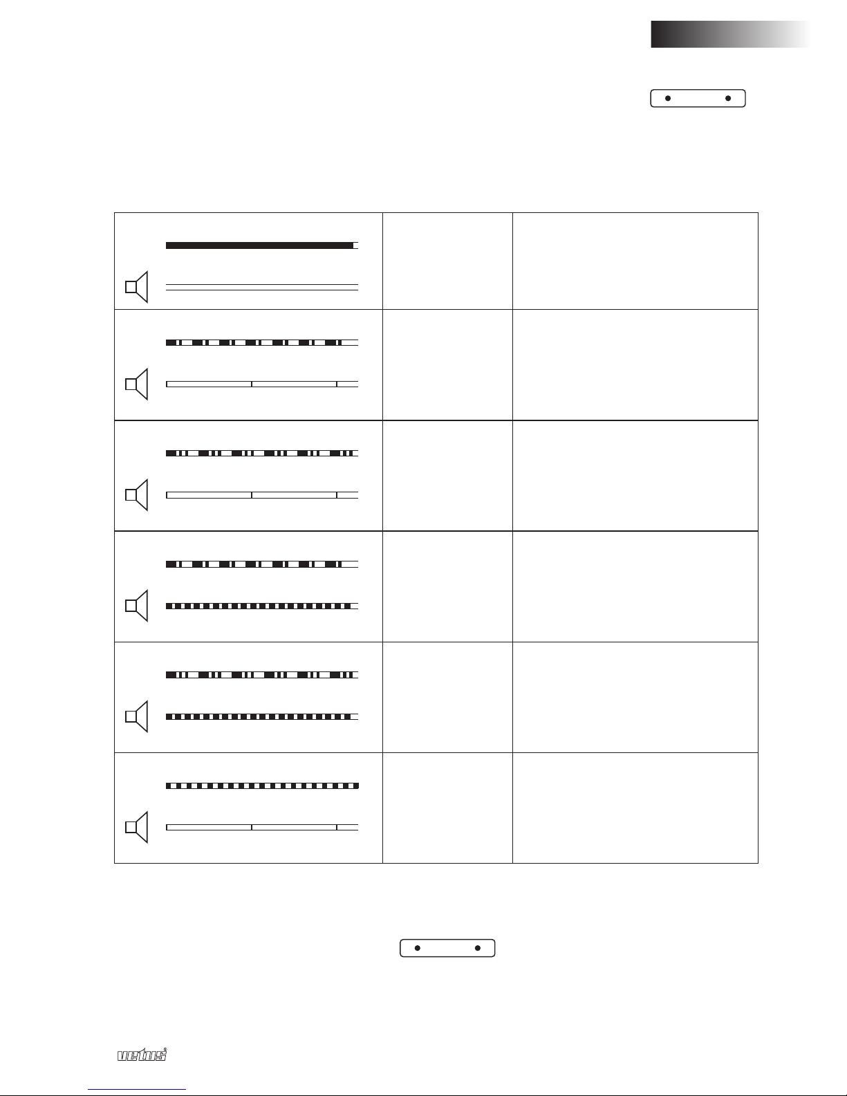
Koolmonoxidegevaar is afhankelijk van een zogenaamd een tijdgewogen gemiddelde;
dit wil zeggen dat het afhankelijk is van zowel de concentratie koolmonoxide als van
de tijd dat de koolmonoxide aanwezig is.
De concentratie van koolmonoxide heeft daarom invloed op de tijdsduur voordat de
gasdetector alarm geeft.
Beide detectiefuncties worden gelijktijdig uitgevoerd.
*) Brandbare gassen en dampen behoren normaal niet of slechts in uiterst geringe
hoeveelheden in de omgevingslucht te zitten.
Brandbare gassen zijn bijv. propaan, butaan, methaan en waterstof. Aardgas bestaat
voor ca. 81 % uit methaan.
**) Koolmonoxide (chemische formule: CO) is een onzichtbaar, kleurloos en reukloos
gas. Het ontstaat bij onvolledige verbranding in apparaten die branden op organi-
sche stoffen zoals olie, gas, benzine, kolen en hout (dus niet in elektrische instal-
laties!). Onvolledige verbranding betekent, dat er onvoldoende zuurstof aanwezig is
voor een goede verbranding.
Als koolmonoxide wordt ingeademd, wordt het via de longen in het bloed opgeno-
men. Hier hecht het zich aan de rode bloedcellen. Rode bloedcellen zorgen voor
het transport van zuurstof door het lichaam. Omdat koolmonoxide zich ruim 200x
makkelijker aan rode bloedcellen hecht dan zuurstof, verdringt het de zuurstof in het
bloed heel gemakkelijk. Het bloed kan daardoor steeds minder zuurstof vervoeren.
De gasdetector kan worden aangesloten op een 12 Volt of een 24 Volt gelijkspannings-
voeding.
De gasdetector kan naar keuze continue of intermitterend gebruikt worden, zie 3.2.
Het verdient aanbeveling altijd op de mogelijke aanwezigheid van gas te con-
troleren; ook wanneer het schip niet in gebruik is!
Houdt daarom de voedingsspanning van de gasdetector altijd ingeschakeld.

100105.02 5
NEDERLANDS
Gasdetector GD1000
Zware vervuiling en hoge vochtconcentraties verminderen de levensduur van de senso-
ren aanzienlijk. Zogenaamde vergiftiging van de sensoren treedt op wanneer deze bij
ingeschakelde toestand worden blootgesteld aan siliconendampen en oplosmiddelen
(schilderwerkzaamheden), freonen (oude koelsystemen), loodhoudende benzinedam-
pen en polyesterhars.
Om schade aan sensoren te voorkomen verdient het aanbeveling onder genoemde
omstandigheden de gasdetector uit te schakelen of zelfs de sensoren tijdelijk uit het
schip te verwijderen.
N.B. De aanwezigheid van brandbare gassen of CO wordt dan niet meer gedetec-
teerd. Verlies de veiligheid niet uit het oog!
Tijdens het meten veroudert de sensor. Bij continue gebruik veroudert de sensor sneller
dan bij intermitterend gebruik. Na circa 2 jaar continue gebruik is de sensor veroudert,
zie ‘4 Veroudering van de sensor’.
2.1 Inhoud van de verpakking
1 Instrument GD1000
1 Sensor
1 Kabel voor aansluiten sensor (5 meter)
2 Schroeven voor montage van de sensor
1 Handleiding

6 100105.02 Gasdetector GD1000
3 Bediening
3.1 Aan- en uitschakelen
Inschakelen : Druk eenmaal kort op de toets.
Uitschakelen : Druk de toets in en houdt deze 5
seconden ingedrukt.
Na het inschakelen zal de gasdetector continue op de
aanwezigheid van gas controleren.
De LED boven de toets zal aan gaan. Deze LED zal
gaan knipperen als de accuspanning te laag is.
Bij het inschakelen van de voedingsspanning wordt
de gasdetector automatisch ingeschakeld, dit om te
voorkomen dat u vergeet hem in te schakelen.
Na ca 1 minuut is de sensor opgewarmd en zal de gasdetector op betrouwbare
wijze de aanwezigheid van gas kunnen detecteren. Tijdens het opwarmen van de
sensor wordt getest of een sensor is aangesloten en of deze correct functioneert.
3.2 Continue of intermitterend controleren op de aanwezigheid van gas
De gasdetector kan naar keuze continue of intermitterend op de aanwezigheid van gas
controleren.
In de intermitterende stand worden de gassensoren 1 minuut ingeschakeld en vervol-
gens 2 minuten uitgeschakeld. Het gemiddelde stroomverbruik is in deze stand lager
dan in de stand continue.
Standaard staat de gasdetector in de stand continue.
Omschakelen van de stand continue naar intermitterende stand of andersom wordt
gedaan door de
CONT
toets in te drukken. In de stand continue is de groene LED boven
de
CONT
toets aan.
Als de gasklep wordt geopend, zie 3.7 wordt automatisch de gasdetector in de stand
continue gezet.
Gebruik bij de stand continue als er personen aan boord zijn.
Gebruik de stand intermitterend als u niet aan boord van het schip verblijft.
3.3 Testen
De werking van de gasdetector kan worden getest door de testcyclus te activeren. Na
het indrukken van de
TEST
toets wordt gedurende 7 seconden een schijnalarm uitge-
voerd. Tijdens dit schijnalarm wordt het volgende getest:
- de werking van de sensoren,
- de werking van het akoestisch alarm,
- het correct functioneren van de bediening van de gasklep en de ventilator; de gas-
klep wordt gesloten en de ventilator wordt ingeschakeld.
Continue controleert de gasdetector of de sensor (of sensoren) zijn aangesloten en of
ze correct functioneren. Indien dit niet het geval is wordt een alarm gegeven.
vetus
GASDETECTOR
SENSOR1 2
CONT
TEST

100105.02 7
NEDERLANDS
Gasdetector GD1000
3.4 Indicatie van de gemeten gasconcentratie (Alarm of veilig)
Middels een akoestisch alarm en twee LED’s, één voor elke sensor
SENSOR1 2
,
wordt aangegeven of er een gasconcentratie door de sensor is gemeten en of de sensor
naar behoren functioneert.
De indicatie is als volgt:
GROEN
LED
Veilig Er wordt geen brandbaar gas
of CO gedetecteerd.
GROEN
LED
1 s - 0,25 s - 0,25 s - 1 s
0,3 s - 8 s
Waarschuwing
CO
Er wordt een minimale CO
gedetecteerd, maar minder
dan het alarmniveau. Dit is het
waarschuwingsgebied.
GROEN
LED
1 s - 0,25 s - 0,25 s - 0,25 - 0,25 s - 1 s
0,3 s - 8 s
Waarschuwing
Brandbaar gas
Er wordt een minimale ho-
eveelheid brandbaar gas
gedetecteerd, maar minder
dan het alarmniveau. Dit is het
waarschuwingsgebied.
ROOD
LED
1 s - 0,25 s - 0,25 s - 1 s
0,6 s - 0,3 s
Alarm
CO
Er wordt een hoeveelheid CO
gedetecteerd hoger dan het
alarmniveau.
ROOD
LED
1 s - 0,25 s - 0,25 s - 0,25 - 0,25 s - 1 s
0,6 s - 0,3 s
Alarm
Brandbaar gas
Er wordt een hoeveelheid
brandbaar gas gedetecteerd
hoger dan het alarmniveau.
ROOD
LED
0,15 s - 8 s
0,5 s - 0,5 s
Attentie De sensor is defect of verou-
derd.
LET OP: Wanneer er geen sensors op de gasdetector zijn aangesloten, kan deze niet
functioneren. De beide sensor led’s
SENSOR1 2
zullen ROOD knipperen totdat er
tenminste 1 sensor is gedetecteerd.

8 100105.02 Gasdetector GD1000
3.5 Akoestisch alarm uitschakelen
Als een alarmtoestand optreedt kan het akoestisch alarm (zoemer) worden uitgescha-
keld door op de toets te drukken.
Indien de alarmtoestand 5 minuten na het indrukken van de toets nog steeds
bestaat wordt het akoestisch alarm opnieuw ingeschakeld.
3.6 Ventilator
Gebruik de toets om de ventilator in- of uit te schakelen. Als de ventilator is inge-
schakeld brandt de groene LED boven de toets. Deze LED zal gaan knipperen als
de accuspanning te laag is.
Als een alarmtoestand optreedt wordt de ventilator automatisch ingeschakeld.
3.7 Gasklep
Gebruik de toets om de gasklep te openen of te sluiten. Als de gasklep geopend
is brandt de groene LED boven de toets. Deze LED zal gaan knipperen als de
accuspanning te laag is.
Als de gasklep wordt geopend wordt automatisch de gasdetector in de stand
continue gezet.
Als een alarmtoestand optreedt ten gevolge van een te hoge concentratie brandbaar
gas of een te hoge concentratie CO wordt de gasklep automatisch gesloten.

100105.02 9
NEDERLANDS
Gasdetector GD1000
LET OP
Voer deze handelingen uitsluitend aan bij de vervangen sensor en niet bij de
eventuele bestaande sensor, waarbij de levenscyclus nog wordt bijgehou-
den, omdat de veroudering hiermee niet meer juist wordt geïnterpreteerd.
Gevaarlijke situaties zouden hierdoor kunnen ontstaan.
4 Veroudering van de sensor
Tijdens het meten veroudert de sensor. De mate van veroudering wordt in de gasde-
tector bijgehouden. Na circa 2 jaar continue gebruik is de sensor veroudert en geeft de
gasdetector een waarschuwing.
De LED van de corresponderende sensor op het paneel gaat rood knipperen en rode
LED op de betreffende sensor zelf gaat branden. Tevens geeft de zoemer het attentie
signaal. Een verouderde sensor dient te worden vervangen.
4.1 Vervangen van de sensor
Monteer een nieuwe sensor en sluit deze aan. De LED op het paneel van de betreffende
sensor zal rood blijven knipperen.
Na het vervangen van de sensor moet dit aan de gasdetector kenbaar worden gemaakt;
de gasdetector zal hierna weer op de correcte wijze de veroudering bijhouden. Handel
hiertoe als volgt:
- Schakel de gasdetector uit, toets.
- Vervang de sensor.
- Schakel de gasdetector weer in, toets.
- Druk de toets in en houdt deze ingedrukt. Druk nu ook de toets in van de cor-
responderende sensor.
Sensor 1: toets +
TEST
toets
Sensor 2: toets + toets
Houdt beide toetsen 10 sec. achtereen ingedrukt.
Hierna volgt een toon welke aangeeft, dat de verouderingstijdklok op 0 is gezet. Laat
beide toetsen los. De corresponderende led gaat groen branden zodra de nieuwe sen-
sor is gedetecteerd en correct functioneert.
Na ca 1 minuut is de sensor opgewarmd en zal de gasdetector op betrouwbare
wijze de aanwezigheid van gas kunnen detecteren.

10 100105.02 Gasdetector GD1000
5 Installatie
5.1 Controlepaneel
Voor afmetingen zie ‘7 Hoofdafmetingen’.
Het paneel is bestemd voor binnenmontage!
Maak met een gatenzaag een gat met een diameter van 76 mm (3") in het instrumen-
tenpaneel of in een schot. Het paneel wordt met behulp van de meegeleverde verende
klemmen in het gat gemonteerd.
Indien de achterzijde niet (goed) bereikbaar is dienen eerst alle aansluitingen te worden
gemaakt alvorens het paneel in het gat te plaatsen.
5.2 Sensoren
Er kunnen naar keuze 1 of 2 sensoren op de gasdetector worden aangesloten.
De sensor dient op de juiste plaats in de ruimte te worden gemonteerd waar een gas-
concentratie kan ontstaan.
5.2.1 Het kiezen van de juiste plaats voor de sensor
De sensor detecteert zowel brandbare gassen als koolmonoxide (CO).
De brandbare gassen propaan en butaan zijn zwaarder dan lucht en moeten zo laag
mogelijk gedetecteerd worden.
Koolmonoxide en de brandbare gassen methaan en waterstof zijn lichter dan lucht en
moeten zo hoog mogelijk gedetecteerd worden.
Het is in een ruimte waarin zich gasgestookte kooktoestellen of verwarmingstoestellen
bevinden uiteraard mogelijk dat zowel gassen in de ruimte voorkomen welke zwaarder
zijn dan lucht en welke lichter zijn dan lucht.
Plaats de sensor bijvoorbeeld in de nabijheid van het kooktoestel op ca. 1,5 meter van
het dek.
Alle voorkomende ruimtes dienen uiteraard goed geventileerd te zijn.
De sensor mag in elke stand geplaatst worden.
De plaats van de sensor dient zo gekozen te worden dat deze te allen tijde vrij blijft van
bilgewater!
5.2.2 Installatie van een 2esensor
Indien tijdens de installatie van de gasdetector aanvankelijk slechts 1 sensor geïnstal-
leerd is en er later een 2esensor wordt bijgeplaatst zal de aanwezigheid van de 2esen-
sor automatisch door de gasdetector herkend worden.
Om betrouwbaar gas te kunnen meten moet de sensor hierna gedurende 1 minuut
opgewarmd worden.

100105.02 11
ENGLISH
Gasdetector GD1000
5.3 Aansluitingen
Sluit de gasdetector aan zoals is aangegeven bij ‘8 Aansluitschema’.
5.3.1 Voedingsspanning
De gasdetector is geschikt voor zowel 12 als 24 Volt.
De zekering in de plusdraad van de gasdetector beveiligd uitsluitend de gasdetector
zelf en niet een eventueel aangesloten gasklep, alarm of ventilator!
5.3.2 Gasklep
Op de uitgang ‘VALVE’ kan een elektrisch bediende gasklep worden aangesloten. De
gasklep is opgenomen in de gastoevoerleiding.
In het geval van een alarmsituatie zal de klep automatisch worden gesloten en zo de
gastoevoer naar de installatie afsluiten.
De spanning waarvoor de gasklep geschikt is moet overeenkomen met de voedings-
spanning van de installatie, respectievelijk 12 of 24Volt gelijkspanning
De uitgang ‘VALVE’ is geschikt voor een gasklep met een stroomverbruik van maximaal
1 A. Neem in de plusdraad naar de gasklep een 1 A zekering op.
Let op: de gasdetector schakelt de min aansluiting (-, massa) van de gasklep!
5.3.3 Extern Alarm
Op de uitgang ‘ALARM’ kan een extern geplaatst alarm (bijvoorbeeld een claxon of een
zoemer) of een contact van een alarminstallatie worden aangesloten.
In het geval van een alarmsituatie zal het externe alarm automatisch worden ingescha-
keld.
De spanning waarvoor het externe alarm (claxon of zoemer) geschikt is moet over-
eenkomen met de voedingsspanning van de installatie, respectievelijk 12 of 24Volt
gelijkspanning
De uitgang ‘ALARM’ is geschikt voor een claxon of zoemer met een stroomverbruik van
maximaal 1 A. Neem in de plusdraad naar de claxon of zoemer een 1 A zekering op.
Let op: de gasdetector schakelt de min aansluiting (-, massa) van de claxon of zoe-
mer!
5.3.4 Ventilator
Op de uitgang ‘FAN’ kan een elektrische ventilator worden aangesloten. De ventilator
dient ervoor om de lucht in de te bewaken ruimten te verschonen.
In het geval van een alarmsituatie zal de ventilator automatisch worden ingeschakeld.
De ventilator moet vonkvrij zijn! (Ignition protected).
De spanning waarvoor de ventilator geschikt is moet overeenkomen met de voedings-
spanning van de installatie, respectievelijk 12 of 24Volt gelijkspanning
De uitgang ‘FAN’ is geschikt voor een ventilator met een stroomverbruik van maximaal
1 A. Neem in de plusdraad naar de ventilator een 1 A zekering op.
Let op: de gasdetector schakelt de min aansluiting (-, massa) van de ventilator!

12 100105.02 Gasdetector GD1000
6 Technische gegevens
Voedingsspanning : 12 Volt of 24 Volt gelijkspanning
Voedingsspanningsgrenzen : 8 tot 30 Volt
Opgenomen stroom Intermitterend : 35 mA gemiddeld
Opgenomen stroom continu (per sensor) : 100mA
Maximale stroom uitgangen
voor ventilator, gasklep en extern alarm : 1A
Lengte sensor kabel : 5 meter
Voor de detectie van propaan (C3H4) en butaan (C4H10) geldt,
Waarschuwing : 3 % van de onderste explosiegrens (LEL) (390 ppm)
Alarm : 6 % van de onderste explosiegrens (LEL) (780 ppm)
Detectie van andere gassen dan propaan en butaan,
- Methaan: Alarm : 3,4 % van de onderste explosiegrens (LEL) (1500 ppm)
- Waterstof Alarm : 5 % van de onderste explosiegrens (LEL) (2000 ppm)
Voor de detectie van CO (koolmonoxide) zijn de volgende gasniveau’s en tijdconstanten
gedefinieerd:
20 40 60 100 200 400 600
300
40
200
60
100
80
400
30
t (min)
CO (ppm)
3
1 2
1 VEILIG
2 WAARSCHUWING CO
3 ALARM CO

100105.02 13
ENGLISH
Contents
1 Safety advice ............... 13
2 Introduction ................ 14
2.1 Contents of the pack ....... 15
3 Operating .................. 16
3.1 Switching on and off .......... 16
3.2 Continuous or intermittent check
for the presence of gas . . . . . 16
3.3 Testing .................. 16
3.4 Indicating the measured gas con-
centration (Alarm or safe) . . . 17
3.5 Switching off the acoustic
alarm ................... 18
3.6 Fan ..................... 18
3.7 Gas valve ................ 18
4 Ageing of the sensor ......... 19
4.1 Replacing the sensor . . . . . . 19
5 Installing ................... 20
5.1 Control panel ............. 20
5.2 Sensors ................. 20
5.2.1 Selecting the right place for
the sensor . . . . . . . . . . . . 20
5.2.2 Installing a 2nd sensor . . . 20
5.3 Connections ............. 21
5.3.1 Power supply ......... 21
5.3.2 Gas valve ............. 21
5.3.3 External Alarm ......... 21
5.3.4 Fan ................. 21
6 Technical details ............ 22
7 Overall dimensions .......... 64
8 Wiring diagram .............. 66
1 Safety advice
Read this manual carefully before taking the gas detector into service and follow the
user instructions.
Also make sure that other people on board are aware of the safety advice.
As soon as the gas detector detects the presence of gas:
- Never switch on any electrical equipment!
- No heat, sparks or naked flames!
- Ventilate the compartment!
- Use soap solution to find the gas leak!
Gas detector GD1000

14 100105.02
2 Introduction
The Vetus gas detector together with one or two sensors forms a gas detection system
with two different functions.
In the first place to detect a range of combustible gases *) to prevent the risk of explo-
sion on board.
Secondly to detect the poisonous gas carbon monoxide (CO) **) to prevent the forma-
tion of a dangerous and poisonous atmosphere for people.
The danger formed by carbon monoxide is dependent on a time-weighted average. This
means that it is dependent on both the concentration of carbon monoxide and the time
that the carbon monoxide is present.
The concentration of carbon monoxide therefore has influence on the time before the
gas detector gives an alarm.
Both detector functions are carried out at the same time.
*) Combustible gases and vapours should not or only in extremely small amounts
be present in the normal surrounding atmosphere.
Combustible gases are e.g. propane, butane, methane and hydrogen. About 81 %
of the composition of natural gas is methane.
**) Carbon monoxide (chemical formula CO) is an invisible, colourless and odour-
less gas. It is formed by incomplete combustion in equipment burning organic
fuels such as oil, gas, petrol, coal and wood (so not in electrical installations!).
Incomplete combustion means that there is insufficient oxygen present to allow
good or complete combustion.
When carbon monoxide is breathed in it is taken up by the blood via the lungs and
attaches itself to the red blood cells. Red blood cells transport oxygen through the
body. Because carbon monoxide attaches to red blood cells about 200x more easily
than oxygen it can very easily displace oxygen from the blood and this can therefore
transport less oxygen.
The gas detector can be connected to a 12 Volt or a 24 Volt direct current power sup-
ply.
The gas detector can be used in either continuous or intermittent mode according to
choice, see 3.2.
It is recommended that a check for the presence of gas should always be
made, even when the ship is not in use!
Therefore, always keep the power supply to the gas detector switched on.
Gas detector GD1000

100105.02 15
ENGLISH
Severe contamination and high concentration of moisture reduce the lifetime of the sen-
sors significantly. Poisoning of the sensors occurs if they are exposed to silicone vapour
and solvents, (painting work), freons (old cooling systems) or vapour from leaded petrol
and polyester resins while they are switched on.
In order to prevent damage to the sensors it is recommended that the gas detector is
switched off under the conditions named above or even to remove the sensors from the
ship temporarily.
N.B. The presence of combustible gas or CO will then no longer be detected. Do
not forget to consider safety!
The sensor ages while being used to measure the concentration, and this is faster dur-
ing continuous than during intermittent use. After about 2 years of continuous use the
sensor will have aged, see ‘4 Ageing of the sensor’.
2.1 Contents of the pack
1 Instrument GD1000
1 Sensor
1 Cable for connecting sensor (5 metres)
2 Screws for fitting the sensor
1 Manual
Gas detector GD1000

16 100105.02
3 Operating
3.1 Switching on and off
Switching on : Briefly press the button once.
Switching off : Press the button and hold down
for 5 seconds.
After switching on the gas detector will check for the
presence of gas continuously.
The LED above the button will come on. This LED
will flash if the battery voltage is too low.
The gas detector is switched on automatically when
the power supply is switched on. This is to prevent you
from forgetting to switch it on.
The sensor will have warmed up after about 1 minute and the gas detector can then
detect the presence of gas reliably. A test is carried out while the sensor is warm-
ing up to see if a sensor is connected and if it is functioning correctly.
3.2 Continuous or intermittent check for the presence of gas
The gas detector can be used to check for the presence of gas in either continuous or
intermittent mode according to choice.
The gas sensors are switched on for 1 minute and then off for 2 minutes when in inter-
mittent mode. The average power consumption is lower in this mode than when used
continuously.
The gas detector is set standard to continuous mode.
Changing from continuous mode to intermittent mode or vice versa is done by pressing
the
CONT
button. The green LED above the
CONT
button is on when in continuous mode.
If the gas valve is opened the gas detector is automatically set to continuous mode,
see 3.7.
Use continuous mode when people are on board.
Use intermittent mode when you are not on board the ship.
3.3 Testing
The working of the gas detector can be tested by activating the test cycle. A false alarm
is given for 7 seconds after pressing the
TEST
button. The following are tested during
this false alarm:
- the working of the sensors
- the working of the acoustic alarm
- the correct functioning of the operation of the gas valve and the fan; the gas valve is
closed and the fan switched on.
The gas detector checks continuously that the sensor or sensors are connected and
functioning correctly. An alarm is given if this is not the case.
vetus
GASDETECTOR
SENSOR1 2
CONT
TEST
Gas detector GD1000

100105.02 17
ENGLISH
3.4 Indicating the measured gas concentration (Alarm or safe)
Whether a gas concentration has been measured by the sensor and whether the sen-
sor is functioning correctly is shown by an acoustic alarm and two LEDs, one for each
sensor.
SENSOR1 2
The indication is as follows:
GREEN
LED
Safe No combustible gas or CO has
been detected.
GREEN
LED
1 s - 0,25 s - 0,25 s - 1 s
0,3 s - 8 s
Warning
CO
A minimum amount of CO has
been detected, but less than the
alarm level. This is in the warn-
ing range.
GREEN
LED
1 s - 0,25 s - 0,25 s - 0,25 - 0,25 s - 1 s
0,3 s - 8 s
Warning
Combustible
gas
A minimum amount of combus-
tible gas has been detected, but
less than the alarm level. This is
in the warning range.
RED
LED
1 s - 0,25 s - 0,25 s - 1 s
0,6 s - 0,3 s
Alarm
CO
An amount of CO higher than
the alarm level has been detect-
ed.
RED
LED
1 s - 0,25 s - 0,25 s - 0,25 - 0,25 s - 1 s
0,6 s - 0,3 s
Alarm
Combustible
gas
An amount of combustible gas
higher than the alarm level has
been detected.
RED
LED
0,15 s - 8 s
0,5 s - 0,5 s
Attention The sensor is faulty or aged.
NB: if no sensors are connected to the gas detector it cannot function. Both LEDs
SENSOR1 2
will flash RED until at least 1 sensor has been detected.
Gas detector GD1000

18 100105.02
3.5 Switching off the acoustic alarm
If there is an alarm situation the acoustic alarm (buzzer) can be switched off by pressing
the button.
If the alarm situation still exists 5 minutes after the button has been pressed the
acoustic alarm will be switched on again.
3.6 Fan
Use the button to switch the fan on and off. When the fan is switched on the green
LED above the button will be on. This LED will flash if the battery voltage is too
low.
The fan is switched on automatically if there is an alarm situation.
3.7 Gas valve
Use the button to open or close the gas valve. When the gas valve is open the
green LED above the button will be on. This LED will flash if the battery voltage is
too low.
If the gas valve is opened the gas detector is automatically set to continuous
mode.
The gas valve is automatically closed if there is an alarm situation as a result of too high
a concentration of combustible gas or too high a concentration of CO.
Gas detector GD1000

100105.02 19
ENGLISH
4 Ageing of the sensor
The sensor ages when it is used for measuring. The extent of the ageing is monitored
by the gas detector. After about 2 years continuous use the sensor is aged and the gas
detector will give a warning.
The LED of the corresponding sensor on the panel will flash red and the red LED on
the particular sensor will also come on. The buzzer will also give the attention signal. A
sensor that has aged must be replaced.
4.1 Replacing the sensor
Fit and connect a new sensor. The LED for the particular panel on the panel will continue
to flash red.
After replacing the sensor this must be made known to the gas detector after which it will
monitor the ageing in the correct way again. Follow the instructions below to do this.
- Switch off the gas detector using the button.
- Replace the sensor.
- Switch on the gas detector again using the button.
- Press and hold down the button. Now also press the button for the particular
sensor.
Sensor 1: button +
TEST
button
Sensor 2: button + button
Keep both buttons pressed in for 10 sec.
A sound will be heard after this to indicate that the ageing clock has been reset to 0.
Release both buttons. The corresponding LED will come on green as soon as the new
sensor has been detected and is functioning correctly.
The sensor will have warmed up after about 1 minute and the gas detector can then
detect the presence of gas reliably.
NB
Only carry out these actions for the sensor that is being replaced and not
for any other existing sensor for which the life cycle is still being monitored,
otherwise the ageing of this will no longer be interpreted correctly. This could
lead to dangerous situations occurring.
Gas detector GD1000

20 100105.02
5 Installing
5.1 Control panel
For dimensions see ‘7 Overall dimensions’.
The panel is for fitting inside!
Use a hole cutter to cut a hole diameter 76 mm (3”) in the instrument panel or in a
bulkhead. Fit the panel in the hole using the spring clamps supplied. If the back of the
panel will not be easily accessible all connections should be made first before position-
ing the panel in the hole.
5.2 Sensors
One or two sensors may be connected to the gas detector as desired. The sensor
must be positioned in the right place in the room in which a concentration of gas could
arise.
5.2.1 Selecting the right place for the sensor
The sensor detects both combustible gases and carbon monoxide (CO).
The combustible gases propane and butane are heavier than air and must be detected
as low as possible.
Carbon monoxide and the combustible gases methane and hydrogen are lighter than
air and must be detected as high as possible.
In a room with gas-fired cooking or heating equipment it is naturally possible that gases
that are both lighter and heavier than air could occur in the room.
Position the sensor about 1.5 metres above the deck in the vicinity of a cooker for
example.
All rooms for which this is important must naturally be well ventilated.
The sensor may be positioned at any angle.
The position of the sensor must be chosen so that it will always be out of the bilge
water!
5.2.2 Installing a 2nd sensor
If a second sensor is fitted later after originally only positioning one sensor during the
installation of the gas detector the presence of the 2nd sensor will automatically be
detected by the gas detector.
In order to measure the concentration of gas reliably the sensor must warm up for
1 minute after this.
Gas detector GD1000
Other manuals for GD1000
1
Table of contents
Languages:
Other Vetus Other manuals
Popular Other manuals by other brands

Taylor Technologies
Taylor Technologies Phoenix v3.0 Upgrade Installation Instructions

SodaStream
SodaStream Soda-Club CY8001 user manual

Cooke & Lewis
Cooke & Lewis Beloya 3663602945109 manual

Ferplast
Ferplast BLUPOWER Series user manual

Digital Watchdog
Digital Watchdog CP-01 instruction manual

Ofil
Ofil Scalar manual