VEVOR MC Series User manual

Technical Support and E-Warranty Certificate www.vevor.com/support
MC SERIES MPPT SOLAR CHARGE
CONTROLLER MC2430N10-B/ MC2440N10-B/ MC2450N10-B
USER MANUAL
We continue to be committed to provide you tools with competitive price.
"Save Half", "Half Price" or any other similar expressions used by us only represents an
estimate of savings you might benefit from buying certain tools with us compared to the major
top brands and doses not necessarily mean to cover all categories of tools offered by us. You
are kindly reminded to verify carefully when you are placing an order with us if you are
actually saving half in comparison with the top major brands.

- 1 -
MODEL:MC2430N10-B/ MC2440N10-B/ MC2450N10-B
Have product questions? Need technical support? Please feel free to
contact us:
Technical Support and E-Warranty Certificate
www.vevor.com/support
NEED HELP? CONTACT US!
This is the original instruction, please read all manual instructions
carefully before operating. VEVOR reserves a clear interpretation of our
user manual. The appearance of the product shall be subject to the
product you received. Please forgive us that we won't inform you again if
there are any technology or software updates on our product.
MC SERIES MPPT SOLAR
CHARGE

- 2 -
Warning-To reduce the risk of injury, user must read
instructions manual carefully.
This device complies with Part 15 of the FCC Rules. Operation is
subject to the following two conditions:(1)This device may not cause
harmful interference, and (2)this device must accept any interference
received, including interference that may cause undesired operation.
This product is subject to the provision of European Directive
2012/19/EC. The symbol showing a wheelie bin crossed
through indicates that the product requires separate refuse
collection in the European Union. This applies to the product
and all accessories marked with this symbol. Products marked
as such may not be discarded with normal domestic waste, but
must be taken to a collection point for recycling electrical and
electronic devices
Model
MC2430N10-B
MC2440N10-B
MC2450N10-B
Battery voltage
12V/24V
Max. PV open circuit
voltage
92V(25℃);100V(Lowest ambient temperature)
Charge current
30A
40A
50A
Max. PV input power
400W/12V
800W/24V
520W/12V
1040W/24V
660W/12V
1320W/24V

- 3 -
Dear users, Thank you very much for choosing our products!
SAFETY INSTRUCTIONS
1. Applicable voltage of the controller exceeds the safety voltage for human
body, so please read the manual carefully before use and operate the
controller only after safety operation training has been completed.
2. There are no parts inside the controller that need to be maintained or
repaired. The user shall not disassemble and repair the controller.
3. Install the controller indoors to prevent exposure of components and
prevent water from entering the controller.
4. Please install the controller in a well-ventilated place to prevent the heat
sink from being overheated.
5. It is recommended to install a proper fuse or circuit breaker outside the
controller.
6. Be sure to disconnect the wiring of PV array and the fuse or circuit
breaker near battery terminal before installation and wiring adjustment of
the controller.
7. Check that all wiring is tight after installation to avoid danger of heat
accumulation due to poor connections.
Warning: This operation is dangerous, so before operation, safety
preparations must be made.
!
Caution: This operation may have a destructive effect.
Reminder: Suggestions and tips for operator.

- 4 -
Table of Contents
1. Introduction...........................................................................................05
2. Installation............................................................................................13
3. Product Operation and Display.............................................................17
4. Product Protection and System Maintenance......................................20
5. Technical Parameters..........................................................................23
6. Conversion Efficiency Curve................................................................25
7. Product Dimensions.............................................................................26

- 5 -
1. INTRODUCTION
1.1 Overview
With industry-leading PowerCatcher MPPT technology, the MC series
solar charge controller enables maximum energy tracking for solar
panels. This technology allows the controller to quickly and accurately
track the maximum power point of PV array in any environment, obtain
the maximum energy of solar panels in real time, and significantly
increase energy utilization efficiency of the solar energy system.
This product can be connected to an external LCD screen or Bluetooth
communication module and PC Upper Computer for dynamic display
of operating status,operating parameters, controller logs,control
parameters, etc. The user can look up various parameters and can
modify the control parameters as needed to suit different system
requirements.
The controller adopts standard Modbus communication protocol,
which is convenient for the user to view and modify the parameters of
the system. Meanwhile, the company provides free monitoring
software that can maximize the convenience for users to meet different
needs of remote monitoring.
The controller provides overall electronic fault self-test and powerful
electronic protection functions which minimize components damage
due to installation error and system failure.
1 .2 F e a t ur e s
PowerCatcher maximum power point tracking technology allows the
controller to track the maximum power point of solar panels even in a
complex environment. Compared with the traditional MPPT tracking
technology, it boasts faster response speed and higher tracking
efficiency.
A built-in maximum power point tracking (MPPT) algorithm can
significantly increase energy utilization efficiency of the photovoltaic

- 6 -
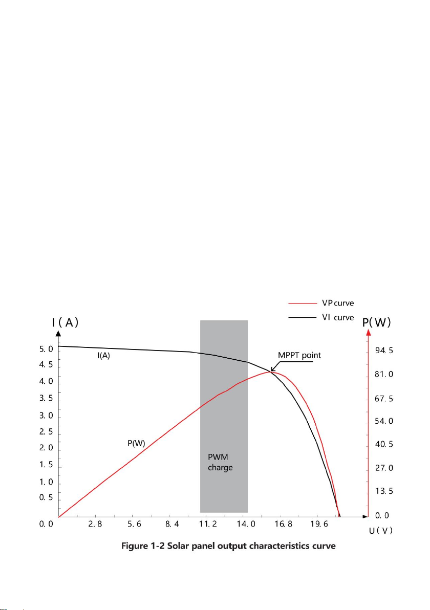
system, which is about 15% to 20% higher than traditional PWM
charging.
It provides an active charging voltage regulation feature. At battery
open circuit or lithium battery BMS overcharge protection, the
controller battery terminal will output the rated charging voltage value.
MPPT tracking efficiency is up to 99.9%.
Due to advanced digital power technology, the circuit energy
conversion efficiency is as high as 98%.
Available in multiple battery types and support charging procedures of
various types of batteries such as lithium battery, colloidal battery,
sealed battery, vented battery, lithium battery, etc.
A current-limited charging mode is available. When the power of solar
panel is too large and the charging current is higher than the rated
valve, the controller automatically reduces the charging power so that
the solar panel can operate at the rated charging current.
Support automatic identification of lead-acid battery voltage.
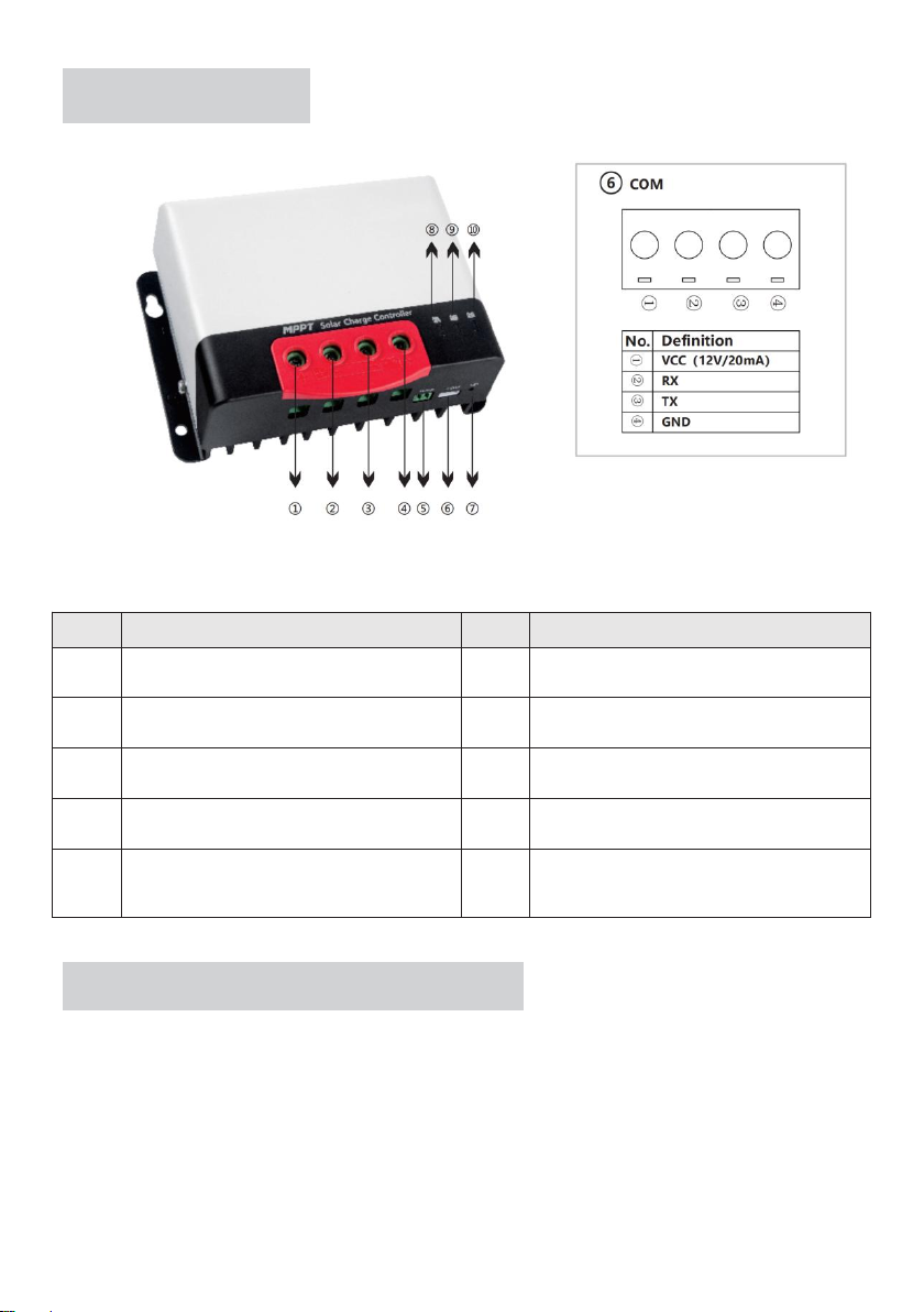
External LCD screen or Bluetooth module can be connected for
viewing of equipment operating data and status, and modification of
controller parameters is supported.
Optional built-in Bluetooth function, which can view the running data
and status of equipment and support the change of controller
parameters.
Optional built-in CAN function, which can view the running data and
status of equipment and support the change of controller parameters.
Support standard Modbus protocol to meet communication needs in
different occasions.
Built-in over-temperature protection mechanism ensures that when
temperature exceeds the set value of the device, the charging current
decreases linearly with the temperature, thereby reducing the
temperature rise of controller and avoiding high temperature damage.
Temperature compensation and automatic adjustment of charge and
discharge parameters help to improve battery life.
Solar panel short circuit protection, battery open circuit protection and
TVS lightning protection, etc.

- 7 -
1 .3 A p pe a r a n c e
Figure 1-1 Controller Appearance and Ports
No.
Names
No.
Names
①
Solar panel "+" interface
⑥
Communication Interface
②
Solar panel "-" interface
⑦
Operation keys
③
Battery "-" interface
⑧
PV charging indicator
④
Battery "+" interface
⑨
Battery level indicator
⑤
External temperature sampling
interface
⑩
Battery type indicator
1 .4 M P PT Te c h n ol o g y In t r o d u ct i o n s
The Maximum Power Point Tracking (MPPT for short) system is an
advanced charging technology that enables the solar panel to output
more energy by adjusting operating conditions of the
electrical module. Due to the non-linear characteristics of solar arrays,
there is a maximum energy output point (maximum power point) of an

- 8 -
array on its curve. Traditional controller (switch charging technology and
PWM charging technology) fails to maintain battery charging at this point,
and therefore the maximum energy of the solar panel cannot be obtained.
The solar charge controller with MPPT control technology, however, can
track the array's maximum power point at all time to obtain the maximum
energy to charge the battery.
Take a 12V system as an example. Peak voltage (Vpp) of the solar panel is
about 17V, while the battery voltage is about 12V. In general, when the
controller is charging the battery, the voltage of solar panel is about 12V
and does not fully contribute to its maximum power. But, MPPT controller
can overcome this problem. It constantly adjusts the input voltage and
current of the solar panel to achieve the maximum input power.
Compared to the traditional PWM controller, the MPPT controller can
provide the maximum power of the solar panel and thus can provide a
larger charging current. In general, the MPPT controller can improve
energy utilization by 15% -20% compared with the PWM controller.

- 9 -
In addition, due to the difference in ambient temperature and light
conditions, the maximum power point often changes. The MPPT controller
can adjust parameters according to different conditions from time to time to
keep the system near its maximum working point. The whole process is
fully automatic and does not require any adjustments
by users.

- 10 -
1 .5 C ha r g i n g St a g e In t r o d uc t i o n s
As one of the charging stages, MPPT cannot be used alone. It is usually
required to combine boost charge, floating charge, equalizing charge and
other charging methods to complete the battery charging process. A
complete charging process includes: Quick charge, holding charge and
floating charge. Charging curve is shown below:
a) Quick charge
In quick charge stage, the battery voltage has not yet reached the set value
of full charge voltage (i.e. equalizing/boost charge voltage) and the
controller will perform MPPT charging, which will provide maximum solar

- 11 -
energy to charge the battery. When the battery voltage reaches the pre-set
value, constant voltage charge will start.
b) Holding charge
When the battery voltage reaches the set value of holding voltage, the
controller will perform constant voltage charging. This process will no
longer include MPPT charging, and the charging current will gradually
decrease with time. Holding charge comes in two stages, i.e. equalizing
charge and boost charge. The two stages are conducted without repetition,
in which equalizing charge is started once every 30 days.
Boost charging
The default duration of boost charge is 2 hours. The customer can also
adjust the holding time and the pre-set value of boost voltage point
according to actual needs. When the duration reaches the set value, the
system will switch to floating charge.
Equalizing charging
Warning: Risk of explosion!
Equalizing vented lead-acid batteries may generate explosive gases. So,
the battery compartment must be well ventilated.
Caution: Damage to the device!
Equalization can increase the battery voltage to levels that may damage
sensitive DC loads. It is necessary to verify that the allowable input voltage
of all system loads is greater than the equalizing charge set value.
Caution: Damage of device!
Over charge and excessive gas evolution may damage the battery plates
and cause active substances on the battery plate to come off. Equalizing
charge may cause damage if voltage is too high or time is too long. Please
carefully check the specific requirements of battery used in the system.
Certain types of battery benefit from regular equalizing charge, which can
stir electrolytes, balance battery voltage, and complete chemical reactions.
Equalizing charge increases the battery voltage above standard voltage,

- 12 -
causing vaporization of battery electrolyte.If it is detected that the controller
automatically controls the next stage to be equalizing charge, the
equalizing charge will last for 120 minutes(default). The equalizing charge
and boost charge are not repeated in a full charge process to avoid too
much gas evolution or battery overheating.
1) When the system cannot continuously stabilize the battery voltage at
a constant voltage due to the influence of installation environment or load,
the controller will accumulate time until the battery voltage reaches the set
value. When the accumulated time reaches 3 hours, the system will
automatically switch to floating charge.
2) If controller clock is not calibrated, the controller will perform regular
equalizing charges according to its internal
Floating charging
Floating charge is conducted following the holding charge stage, where the
controller will reduce the battery voltage by reducing charge current and
allowing the battery voltage to remain at the floating charge set value.
During the floating charge stage, the battery is charged in a very low
voltage to maintain full charge state of the battery. In this stage, the load
can get nearly all of the solar energy. If the load exceeds the energy that
solar panel can provide, the controller will not be able to maintain the
battery voltage in the floating charge stage. When the battery voltage is as
low as the recovery charge set point, the system will exit floating charge
stage and re-enter the fast charge stage.

- 13 -
2. INSTALLATION
2 .1 I ns t a l la t i o n P r ec a u t i on s
Be very careful when installing the battery. When installing the vented
lead-acid battery, wear protective glasses. Once you touch the battery acid,
rinse it with clean water.
Avoid placing metal objects near the battery to prevent battery short circuit.
Acid gas may be generated when the battery is charged. So ensure good
ventilation.
The battery may generate flammable gas. Please keep away from sparks.
Avoid direct sunlight and infiltration of rainwater when installing outdoors.
Poor connection points and corroded wires may cause extreme heat to
melt the wire insulation layer, burn the surrounding materials, and even
cause fire. Therefore, it is necessary to ensure that the connectors are
tightened, and the wires preferably fixed with a cable tie to avoid loose
connectors caused by wire shaking.
In system wiring, output voltage of the component may exceed the safety
voltage of human body. So, it is necessary to use insulated tools and
ensure that the hands are dry.
Battery terminal on the controller can be connected with either a single
battery, or a pack of batteries. Subsequent instructions in the manual are
for a single battery, but it also applies to a battery pack.
Observe the safety recommendations of battery manufacturer.
The system connection wires are selected according to the current density
of not more than 4A/mm2. Make the controller grounded.
2 .2 Wi r i n g Sp e c i fi c a t io n s
Wiring and installation must comply with national and local electrical code
requirements.
PV and battery connection wires must be selected according to rated
current. Refer to the following table for wiring specifications:

- 14 -
Models
PV maximum
Input current
Max. wire
diameter at PV
end(mm²/AWG)
Rated charge
current
Battery wire
diameter
(mm²/AWG)
MC2430N10-B
30
8/8
30A
8/8
MC2440N10-B
40
10/7
40A
10/7
MC2450N10-B
50
12/6
50A
12/6
2 .3 I ns t a l la t i o n an d W ir i n g
Warning: Danger, Explosion! Never install the controller and a
vented battery in the same enclosed space! Also do not install in an
enclosed place where battery gas may collect.
Warning: Danger, High Voltage! Photovoltaic arrays may generate
very high open circuit voltages. Disconnect circuit breaker or fuse before
wiring and be very careful during wiring.
Caution: When installing
the controller, ensure that there is
enough air to flow through the
controller's heat sink, leaving at
least 150mm above and below
the controller to ensure natural
convection for heat dissipation. If
install in a closed box, ensure
reliable heat dissipation through
the box.

- 15 -
Step 1: Choose an installation location
Avoid installing the controller in a place free of direct sunlight, high
temperature, and water, and ensure good
ventilation around the controller.
Step 2: Mark the mounting position according to the mounting
dimensions of the controller. Drill 4 mounting holes of the appropriate
size at the 4 marks. Fix screws into the upper two mounting holes.
Step 3: Fasten the Controller
Align fixing holes of the controller with the two pre-fixed screws and hang
the controller up. And then fix the lower two screws.
Step 4: wire
For installation safety, we recommend a wiring sequence as follows;
however, wiring in other sequences instead of this one will not damage the
controller.

- 16 -
Warning: Danger, Electric shock hazards! We strongly recommend
connect a fuse or circuit breaker to the PV array and battery terminals to
prevent electric shock hazards during wiring or error operation, and make
sure that fuse or circuit breaker is disconnected before wiring.
Warning: Danger, High voltage hazards! Photovoltaic arrays may
generate very high open circuit voltages. Disconnect circuit breaker or fuse
before wiring and be very careful during wiring.
Warning: Danger, Explosion hazards! If the positive and negative
terminals of battery and the wires connected to them are short-circuited, it
may cause a fire or explosion. Please be very careful in operation.
Please connect the battery first, and then the solar panel. Please follow the
“ +” first and “-” next method when wiring.
When all wires are connected firmly and reliably, check whether the wiring
is proper and whether the polarity is reversed. After confirmation, connect
the battery fuse or circuit breaker and observe whether the LED indicator is
on. If not, disconnect the fuse or circuit breaker immediately and check

- 17 -
whether wiring is correct.
As the battery is properly energized, connect the solar panel. If there is
sufficient sunlight, the charge indicator of controller will be steady on or
flash and start to charge the battery.
Warning: When the controller has stopped charging for 10 minutes,
reverse polarity of the battery can damage the controller's internal
components.
Note:
1) Note that the battery fuse shall be installed as close as possible to
the battery terminal. The recommended distance is not more than
150mm.
2) The battery temperature is 25°C (fixed value) when the controller is
not collected to a remote temperature sensor.
3. PRODUCT OPERATION AND DISPLAY
3 .1 L ED I n d ic a t o r s
There are a total of three indicators on the controller
①---PV array indication
Indicate the current charging
mode of controller
②---BAT indication
Indicate the current state of
battery.
③---BAT Type indication
Indicate the current battery type.

- 18 -
PV array indicator:
No.
CHARGE STATUS
Indicator state
Charging state
①
Steady on
MPPT charging
②
Slow flashing
(On:1s, off: 1s, cycle: 2s)
Boost charging
③
Single flashing
(On:0.1s, off: 1.9s, cycle: 2s)
Floating charging
④
Quick flashing
(On:0.1s, off: 0.1s, cycle: 0.2s)
Equalizing
charging
⑤
Double flashing
(On:0.1s, off: 0.1s, then,
On:0.1s, off: 1.7s, cycle: 0.2s)
Current-limited
charging
⑥
Off
No charging
BAT indicator:
Indicator color
Indicator status
Battery status
Green
Steady on
Battery full charge
Yellow
Steady on
Battery voltage normal
Red
Steady on
Battery voltage below under-voltage
point
Quick flash
(On:0.1s, off: 0.1s, cycle: 0.2s)
Battery over-voltage or over temperature

- 19 -
BAT Type Indication:
Indicator color
Battery status
Green
Sealed lead-acid battery
Yellow
Colloidal lead-acid battery
Red
Vented lead-acid battery
Blue
Lithium iron phosphate battery 12V
Purple
Lithium iron phosphate battery 24V
White
Custom
3 .2 K ey s O pe r a t i o n
There is a key on the controller, which is used in conjunction with the
battery type indicator for selection of battery type. The specific operation
mode is as follows:
In the current operating state, press and hold the key for 8 seconds. The
battery type indicator (the color displayed is that of the previously saved
battery type) starts to flash (the controller turns off charging and other
works and enters an idle state). At this point, each time the key is pressed,
the battery type indicator changes a color that corresponds to a battery
type. After the battery type is selected, press and hold the key for 8
seconds again or maintain no operation for 15 seconds. Then, the
controller will automatically save the currently set battery type and enter
the normal operating mode;
In addition, if you press and hold the key for 20s, the controller will restore
the factory default parameters.
3 .3 T T L C om m u n i c at i o n
Users can utilize external communication equipment (such as Bluetooth
BT-2) or communication protocol to perform data monitoring, parameter
setting and other operations for the controller via the port.
T he interface is defined as follows:
This manual suits for next models
3
Table of contents
Other VEVOR Batteries Charger manuals