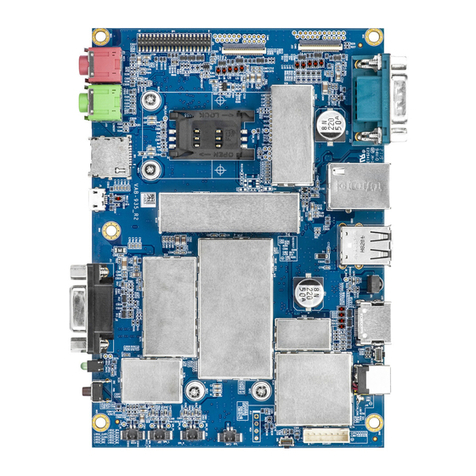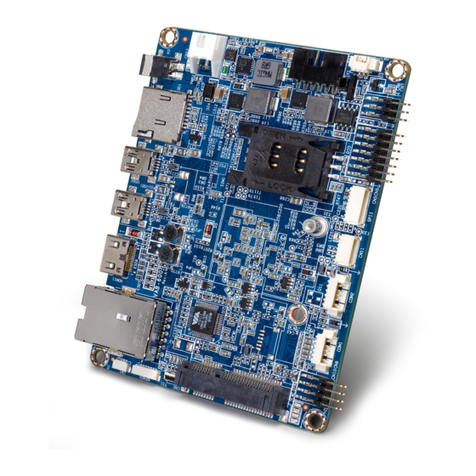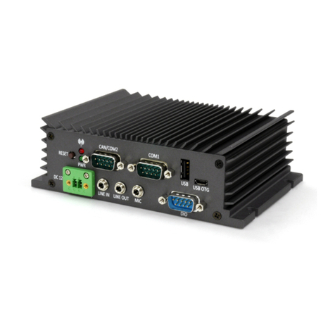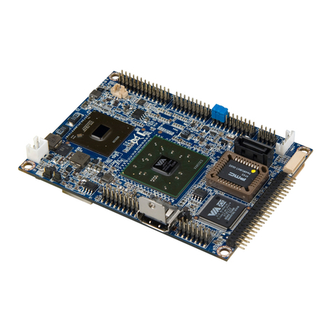
VIA SOM-9X35 Module User Manual
vi
List of Figures
Figure 01: VIA SOM-9X35 module layout (top view) ��������������������������������������������������������������������������������������������� 4
Figure 02: Dimensions of the VIA SOM-9X35 module (top view) ������������������������������������������������������������������������� 4
Figure 03: UART debug connector������������������������������������������������������������������������������������������������������������������������� 5
Figure 04: I-PEX connector ������������������������������������������������������������������������������������������������������������������������������������ 6
Figure 05: VIA SOM-9X35 module installaon ������������������������������������������������������������������������������������������������������ 7
Figure 06: Securing the VIA SOM-9X35 module to the carrier board�������������������������������������������������������������������� 7
Figure 07: Connecng the Wi-Fi antenna�������������������������������������������������������������������������������������������������������������� 8
Figure 08: VIA VAB-935 carrier board layout (top view)�������������������������������������������������������������������������������������� 10
Figure 09: VIA VAB-935 carrier board front panel I/O ����������������������������������������������������������������������������������������� 10
Figure 10: VIA VAB-935 carrier board rear panel I/O ������������������������������������������������������������������������������������������ 10
Figure 11: VIA VAB-935 carrier board layout (boom view) ������������������������������������������������������������������������������� 11
Figure 12: Dimensions of the VIA VAB-935 carrier board (top view) ������������������������������������������������������������������ 11
Figure 13: External I/O dimensions of the VIA VAB-935 carrier board (front panel)������������������������������������������� 11
Figure 14: External I/O dimensions of the VIA VAB-935 carrier board (back panel) ������������������������������������������� 12
Figure 15: Height distribuon of the VIA VAB-935 carrier board (top view) ������������������������������������������������������� 12
Figure 16: Height distribuon of the VIA VAB-935 carrier board (boom view)������������������������������������������������� 12
Figure 17: miniPCIe slot��������������������������������������������������������������������������������������������������������������������������������������� 13
Figure 18: SIM card slot��������������������������������������������������������������������������������������������������������������������������������������� 14
Figure 19: Baery charger connector������������������������������������������������������������������������������������������������������������������ 15
Figure 20: RTC baery connector������������������������������������������������������������������������������������������������������������������������ 16
Figure 21: Speaker connectors ���������������������������������������������������������������������������������������������������������������������������� 16
Figure 22: On-board MIC connector�������������������������������������������������������������������������������������������������������������������� 17
Figure 23: MCU upgrade pin header ������������������������������������������������������������������������������������������������������������������� 18
Figure 24: MIPI CSI 4-lane connectors����������������������������������������������������������������������������������������������������������������� 18
Figure 25: Download buon & pin ���������������������������������������������������������������������������������������������������������������������� 19
Figure 26: I/O expansion header ������������������������������������������������������������������������������������������������������������������������� 20
Figure 27: MIPI DSI 4-lane connector������������������������������������������������������������������������������������������������������������������ 21
Figure 28: LVDS connector����������������������������������������������������������������������������������������������������������������������������������� 22
Figure 29: 7” Touchscreen connector������������������������������������������������������������������������������������������������������������������ 23
Figure 30: 6-pin 1.25mm pitch 10.1” touchscreen connector����������������������������������������������������������������������������� 24
Figure 31: 6-pin 0.5mm pitch 10.1” touchscreen connector������������������������������������������������������������������������������� 25
Figure 32: MIPI CSI 2-lane connectors����������������������������������������������������������������������������������������������������������������� 26
Figure 33: M.2 connectors����������������������������������������������������������������������������������������������������������������������������������� 27
Figure 34: M.2 connector placement - carrier board external I/O ��������������������������������������������������������������������� 28
Figure 35: HDMI port������������������������������������������������������������������������������������������������������������������������������������������� 29
Figure 36: USB 2.0 port���������������������������������������������������������������������������������������������������������������������������������������� 29
Figure 37: 10/100Mbps Ethernet port ���������������������������������������������������������������������������������������������������������������� 30
Figure 38: COM port�������������������������������������������������������������������������������������������������������������������������������������������� 30
Figure 39: IR receiver������������������������������������������������������������������������������������������������������������������������������������������� 31
Figure 40: DC jack������������������������������������������������������������������������������������������������������������������������������������������������ 31
Figure 41: Reset buon & pin������������������������������������������������������������������������������������������������������������������������������ 31
Figure 43: Headphone jack���������������������������������������������������������������������������������������������������������������������������������� 32
Figure 44: Microphone jack��������������������������������������������������������������������������������������������������������������������������������� 32
Figure 45: Power buon�������������������������������������������������������������������������������������������������������������������������������������� 32
Figure 42: Micro USB 2.0 port ���������������������������������������������������������������������������������������������������������������������������� 32
Figure 48: DIO port���������������������������������������������������������������������������������������������������������������������������������������������� 33
Figure 46: MicroSD card slot ������������������������������������������������������������������������������������������������������������������������������� 33
Figure 47: Power buon�������������������������������������������������������������������������������������������������������������������������������������� 33
Figure 49: Installing a PCIe Mini Card ������������������������������������������������������������������������������������������������������������������ 36
Figure 50: Securing the PCIe Mini Card ��������������������������������������������������������������������������������������������������������������� 36
Figure 51: Connecng the 39-pin FFC cable of the 7” TFT-LCD display to 'J7' ����������������������������������������������������� 37
Figure 52: Connecng the 30-pin FFC cable of the 7” touchscreen to 'J9' ���������������������������������������������������������� 37
