manuals.online logo
Brands
  1. Home
  2. •
  3. Brands
  4. •
  5. VIA Technologies
  6. •
  7. Control Unit
  8. •
  9. VIA Technologies ETX-8X90 User manual

VIA Technologies ETX-8X90 User manual

Note:
Note:Note:
Note:
The ETX-8X90 only supports two channel of storage. The SATA2 + IDE1 configuration is
the default setting. The other configurations such as SATA1 + SATA2 or IDE1 + IDE2 are
manufacturing options. For more details, please contact your local sales representative.
Hard disk
Hard diskHard disk
Hard disk
▪
Support two SATA 3.0 Gbps connectors (SATA1 and
SATA2 on module)
▪
Support two IDE connectors (IDE1 and IDE2 on carrier
board)
▪
95% relative humidity
▪
1 x Backlight and Panel power select jumper
▪
1 x LPT pin header
▪
1 x Keyboard and Mouse pin header
▪
1 x COM pin header
▪
1 x Front Panel pin header (for HDD LED, Power LED, Switch
and Speaker
▪
1 x Front Audio pin header
▪
1 x SMBus pin header
▪
1 x I²C pin header
▪
1 x SIR (infrared) pin header
Onboard Jumper
Onboard JumperOnboard Jumper
Onboard Jumper
LCD Interface
LCD Interface LCD Interface
LCD Interface
▪
Support dual-channel 18/24 bit LVDS panel
Graphics processor
Graphics processorGraphics processor
Graphics processor
▪
Integrated VIA UniChrome9™ HD DX9 3D/2D
graphics with MPEG-2,WMV9, and H.264 video
decoding accelerator
Operating System
Operating SystemOperating System
Operating System
▪
Microsoft Windows 7
▪
Microsoft Windows Xpe
▪
Microsoft Windows Embedded System System 7
▪
Microsoft Windows CE 6.0
▪
Linux (Debian, Ubuntu)
▪
VXWorks 6.9
System Memory
System MemorySystem Memory
System Memory
▪
1 x DDR3 1066/800 horizontal type SODIMM socket
▪
Support up to 4GB memory size
ETX-8X90
Computer-On-Module
and
ETXDB1
Carrier Board Reference
Model Name
Model NameModel Name
Model Name
▪
ETXDB1
ETXDB1 Carrier Board Specifications
ETXDB1 Carrier Board SpecificationsETXDB1 Carrier Board Specifications
ETXDB1 Carrier Board Specifications
Rear I/O Connector
Rear I/O ConnectorRear I/O Connector
Rear I/O Connector
▪
1 x VGA connector
▪
1 x COM connector
▪
4 x USB 2.0 ports
▪
1 x RJ-45 LAN port (10/100 Mbit)
Operating and Storage Humidity
Operating and Storage HumidityOperating and Storage Humidity
Operating and Storage Humidity
Expansion Buses
Expansion Buses Expansion Buses
Expansion Buses ▪
Support SMBus interface
▪
Support I²C bus
▪
Support PCI 2.3, 32 bit/33MHz, 2 slots
▪
Support ISA bus (ETX 3.0 compliant) (DMA transfer not
supported)
COM
COMCOM
COM
▪
Support two UARTs port
LPT
LPTLPT
LPT
▪
Support one LPT port
CRT Interface
CRT InterfaceCRT Interface
CRT Interface
▪
350 MHz RAMDAC
▪
Support up to 2048 x 1536 resolution
Chipset
ChipsetChipset
Chipset
▪
VIA VX900 all-in one chipset
Core
CoreCore
Core
Processor
ProcessorProcessor
Processor
▪
VIA Nano X2 1.2+ GHz NanoBGA2 (U4300)
ETX
ETXETX
ETX-
--
-8X90 Module Specifications
8X90 Module Specifications8X90 Module Specifications
8X90 Module Specifications
Graphics memory
Graphics memoryGraphics memory
Graphics memory
▪
UMA, up to 512 MB (BIOS setting)
Audio
AudioAudio
Audio
▪
VT2021 Audio Codec
LAN
LANLAN
LAN
▪
10/100 Mbit Ethernet (RTL8139DL)
USB
USBUSB
USB
▪
Support up to four USB 2.0 ports (on carrier board)
▪
Support two mini USB 2.0 ports (on module)
Operating Humidity
Operating HumidityOperating Humidity
Operating Humidity
▪
0% to 95% (relative humidity; non-condensing)
Storage Temperature
Storage TemperatureStorage Temperature
Storage Temperature
▪
-40°C to 70°C
Compliance
Compliance Compliance
Compliance
▪
CE, FCC and RoHS
Dimension
DimensionDimension
Dimension
▪
95 mm x 114 mm
Operating Temperature
Operating Temperature Operating Temperature
Operating Temperature ▪
0°C up to 60°C
Graphics and Video
Graphics and VideoGraphics and Video
Graphics and Video
Input/Output
Input/OutputInput/Output
Input/Output
Mechanical and Environment
Mechanical and EnvironmentMechanical and Environment
Mechanical and Environment
Key Features:
Key Features:Key Features:
Key Features:
•
VIA Nano X2 1.2+ GHz processor
•
Support DDR3 SODIMM memory
•
Integrated VIA UniChrome9™ HD DX9
2D/3D graphics processor
•
Display interface in CRT, 18/24-bit
dual-channel LVDS panel
•
Support standard and mini USB 2.0 ports
•
Support micro SD card reader
Top View
Top ViewTop View
Top View
Bottom View
Bottom ViewBottom View
Bottom View
Back Panel I/O
Back Panel I/OBack Panel I/O
Back Panel I/O
Connectors and Slots
Connectors and SlotsConnectors and Slots
Connectors and Slots
ETX
ETXETX
ETX-
--
-8X90 Module Layout Diagram
8X90 Module Layout Diagram8X90 Module Layout Diagram
8X90 Module Layout Diagram
Quick Guide
Onboard Connector and Slot
Onboard Connector and SlotOnboard Connector and Slot
Onboard Connector and Slot
▪
4 x ETX connectors
▪
1 x ISA slot (compatible with ISA ETX 3.02)
▪
2 x IDE connectors
▪
2 x PCI slots (compatible with PCI 2.3, 32 bit, 33MHz)
▪
1 x LVDS connector (compatible with TIA/ELA-644)
-
--
-
Pixel clock up to 85 MHz
-
--
-
Support panel resolution up to WXGA 1366 x 768
-
--
-
Supports one or two-channel 18-bit/ 24-bit LVDS panel
▪
1 x Back light connector
▪
1 x ATX power connector
▪
1 x RTC battery socket
Operating Temperature
Operating TemperatureOperating Temperature
Operating Temperature
▪
0°C up to 60°C
BIOS
BIOS BIOS
BIOS
▪
AMI BIOS
▪
8Mbit SPI flash memory
Pin headers and Jumpers
Pin headers and JumpersPin headers and Jumpers
Pin headers and Jumpers
Chipset
ChipsetChipset
Chipset
▪
Realtek RTL8139DL ethernet controller
Ethernet
EthernetEthernet
Ethernet
Micro SD card
Micro SD cardMicro SD card
Micro SD card
▪
Support Micro SD card reader (support OS boot on
Linux Windows CE and VxWorks)
Storage
StorageStorage
Storage
Keyboard/Mouse
Keyboard/Mouse Keyboard/Mouse
Keyboard/Mouse ▪
Support PS/2 keyboard and mouse
IrDA
IrDAIrDA
IrDA
▪
Support SIR
Super IO
Super IOSuper IO
Super IO
▪
Fintek F71869ED
ETX Compliance
ETX Compliance ETX Compliance
ETX Compliance
▪
ETX 3.02, Compact Module
Onboard Pin Header
Onboard Pin HeaderOnboard Pin Header
Onboard Pin Header
Onboard Speaker
Onboard SpeakerOnboard Speaker
Onboard Speaker
▪
1 x Buzzer speaker
Form Factor and Dimension
Form Factor and DimensionForm Factor and Dimension
Form Factor and Dimension
▪
Mini-ITX
▪
6 layers
▪
17 cm x 17 cm
ETXDB1 Carrier board External I/O
Connectors
ETXDB1 Carrier Board Layout Diagram
Top View
Top ViewTop View
Top View
Bottom View
Bottom ViewBottom View
Bottom View
ETX
ETXETX
ETX-
--
-8X90 Module Dimensions
8X90 Module Dimensions8X90 Module Dimensions
8X90 Module Dimensions
Switch and Jumper
Switch and Jumper Switch and Jumper
Switch and Jumper ▪
DIP switch (HDD selector switch)
▪
Clear CMOS jumper
Notes:
Notes:Notes:
Notes:
1. As default, SATA2 connector is enabled and SATA1 connector is
disabled. The SATA1 connector is a manufacturing option.
2. The SATA connector pin 7 default setting is GND. The +5V supports
is a factory option
3. DCIN1, VGA1, LPC1 and SPI1 connectors are reserved for debugging
purposes only, and not for production used.
Board Storage Channel Configuration
Board Storage Channel ConfigurationBoard Storage Channel Configuration
Board Storage Channel Configuration
ETXDB1
ETXDB1ETXDB1
ETXDB1
(Carrier Board)
(Carrier Board)(Carrier Board)
(Carrier Board)
ETX
ETXETX
ETX-
--
-8X90
8X90 8X90
8X90
(Computer
(Computer(Computer
(Computer-
--
-On
OnOn
On-
--
-Module)
Module)Module)
Module)
IDE1
IDE1IDE1
IDE1
IDE2
IDE2IDE2
IDE2
SATA1
SATA1SATA1
SATA1
SATA2
SATA2SATA2
SATA2
Default settings
Enable
Disable Disable
Enable
Manufacturing option 1 Disable Disable Enable Enable
Manufacturing option 2 Enable Enable Disable Disable
VIA Technologies, Inc.
VIA Technologies, Inc.VIA Technologies, Inc.
VIA Technologies, Inc.
1F, 531, Zhong-zheng Road, Xindian District,
New Taipei City 231, Taiwan
Tel: 886-2-2218-5452
Fax: 886-2-2218-5453
Web: www.via.com.tw
Copyright © 2014 VIA Technologies, Inc. All rights reserved.
For more information on this and other VIA
products, please visit www.viaembedded.com
For further support and service, please visit
www.via.com.tw
Mounting ETX-8X90 onto the
ETXDB1 carrier board
Step 1
Align the four ETX connectors and mounting hole of the ETX-8X90
module into the ETX connectors and mounting holes on the ETXDB1
carrier board.
Step 2
Gently press down the ETX-8X90 module until the four ETX connectors
have been fully inserted into the ETX connectors on the ETXDB1 carrier
board.
Step 9
Secure the ETX-8X90 module with the heatsink/heat spreader by
screwing and tightening four M2.5*12 screws in sequence
(torque is 2.5~2.6 kgfcm)
1
Pin
PinPin
Pin
Signal
SignalSignal
Signal
Pin
PinPin
Pin
Signal
SignalSignal
Signal
1 DCD2- 2 RXD2-
3 TXD2- 4 DTR2-
5 GND 6 DSR2-
7 RTS2 8 CTS2
9 RI2 10 Key
Pin
PinPin
Pin
Signal
SignalSignal
Signal
Pin
PinPin
Pin
Signal
SignalSignal
Signal
1 +5VSUS 2 +5VSUS
3 NC 4 Key
5 GND 6 GND
7 KB_DT 8 MS_DT
9 KB_CK 10 MS_CK
Pin
PinPin
Pin
Signal
SignalSignal
Signal
Pin
PinPin
Pin
Signal
SignalSignal
Signal
1 -STB 2 -AFD
3 D0 4 -ERR
5 D1 6 -INIT
7 D2 8 -SLIN
9 D3 10 GND
11 D4 12 GND
13 D5 14 GND
15 D6 16 GND
17 D7 18 GND
19 -ACK 20 GND
21 BUSY 22 GND
23 PE 24 GND
25 SCLT 26 Key
Pin 3
Pin 3Pin 3
Pin 3
Pin 5
Pin 5Pin 5
Pin 5
On Off
On On
Backlight voltage settings
Backlight voltage settingsBacklight voltage settings
Backlight voltage settings
+12V
+5V
Pin 1
Pin 1Pin 1
Pin 1
On
Off
Pin 4
Pin 4Pin 4
Pin 4
Pin 6
Pin 6Pin 6
Pin 6
On Off
On On
Panel voltage settings
Panel voltage settingsPanel voltage settings
Panel voltage settings
+3.3V
+5V
Pin 2
Pin 2Pin 2
Pin 2
On
Off
LPT pin header
LPT pin headerLPT pin header
LPT pin header
COM pin header
COM pin headerCOM pin header
COM pin header
Backlight and Panel Power select jumper
Backlight and Panel Power select jumperBacklight and Panel Power select jumper
Backlight and Panel Power select jumper
Pin
PinPin
Pin
Signal
SignalSignal
Signal
Pin
PinPin
Pin
Signal
SignalSignal
Signal
1 Power LED+ 2 +5V
3 Power LED+ 4 HDD LED-
5 Power LED- 6 Power button
7 +5V 8 GND
9 NC 10 Reset
11 NC 12 GND
13 Speaker- 14 +5V
15 Key 16 NC
Front panel pin header
Front panel pin headerFront panel pin header
Front panel pin header
Step 3
Align the notch on the memory module with the notch on the
SODIMM socket. Insert the memory module into the socket at
30 degrees angle.
Step 4
Push down until the memory module snaps into place. The
memory socket has two locking mechanisms that will click once
the memory module has been fully inserted.
Step 5
Flip over the heatsink/heat spreader. Remove the plastic cover of
the thermal pad of the memory and chipset.
Step 7
Gently install the heatsink/heat spreader. Make sure to install it
in proper orientation. The thermal pads underneath the heatsink/
heat spreader should position above the memory and chipset
respectively.
Step 6
Apply the thermal grease/paste onto the surface of the CPU.
Then align the heatsink/heat spreader over the mounting holes
on the ETX-8X90 module.
ETXDB1 Carrier board Pin headers
Definition and Jumpers Settings
Pin
PinPin
Pin
Signal
SignalSignal
Signal
Pin
PinPin
Pin
Signal
SignalSignal
Signal
1 AUXAR 2 AGND
3 AUXAL 4 MICIN
5 SNDR 6 NC
7 SNDL 8 AGND
Pin
PinPin
Pin
Signal
SignalSignal
Signal
1 +5V
2 Key
3 IRRX
4 GND
5 IRTX
Front Audio pin header
Front Audio pin headerFront Audio pin header
Front Audio pin header Serial Infrared pin header
Serial Infrared pin headerSerial Infrared pin header
Serial Infrared pin header
ETX-8X90 Module Switch and Jumper
Settings
Pin
PinPin
Pin
Signal
SignalSignal
Signal
1 +3V
2 CLK
3 DAT
4 GND
SMBus pin header
SMBus pin headerSMBus pin header
SMBus pin header
Pin
PinPin
Pin
Signal
SignalSignal
Signal
1 +5V /+3V (optional)
2 CLK
3 DAT
4 GND
I²C pin header
I²C pin headerI²C pin header
I²C pin header
Pin 2
Pin 2Pin 2
Pin 2
Pin 3
Pin 3Pin 3
Pin 3
On Off
On On
Clear CMOS settings
Clear CMOS settingsClear CMOS settings
Clear CMOS settings
Normal Operation (default)
Clear CMOS
Pin 1
Pin 1Pin 1
Pin 1
On
Off
Clear CMOS jumper
Clear CMOS jumperClear CMOS jumper
Clear CMOS jumper
HDD selector switch
HDD selector switchHDD selector switch
HDD selector switch
HDD (IDE and SATA) select settings
HDD (IDE and SATA) select settingsHDD (IDE and SATA) select settings
HDD (IDE and SATA) select settings
Switch 1
Switch 1Switch 1
Switch 1
Switch 2
Switch 2Switch 2
Switch 2
Enable SATA1 and SATA2 On On
Enable SATA1 and IDE2 On Off
Enable IDE1 and SATA2 (default setting) Off On
Enable IDE1 and IDE2 Off Off
Keyboard & Mouse pin header
Keyboard & Mouse pin headerKeyboard & Mouse pin header
Keyboard & Mouse pin header
Step 8
Connect the CPU fan jack to the fan connector (FAN1).
○
1
○
3
○
4
○
2
Note:
Note:Note:
Note:
Be sure to follow the sequence shown below when tightening the
screws, otherwise it may cause damage to the device.

Other manuals for ETX-8X90

1

This manual suits for next models

1

Other VIA Technologies Control Unit manuals

VIA Technologies VNT9271BB05B User manual

VIA Technologies

VIA Technologies VNT9271BB05B User manual

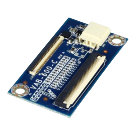
VIA Technologies VAB-600-C User manual

VIA Technologies

VIA Technologies VAB-600-C User manual

VIA Technologies VX800 Series Owner's manual

VIA Technologies

VIA Technologies VX800 Series Owner's manual

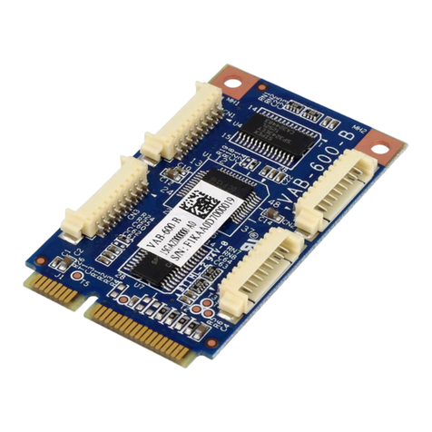
VIA Technologies VAB-600-B User manual

VIA Technologies

VIA Technologies VAB-600-B User manual

VIA Technologies SOM-9X35-STK User manual

VIA Technologies

VIA Technologies SOM-9X35-STK User manual

VIA Technologies QSM-8Q60 User manual

VIA Technologies

VIA Technologies QSM-8Q60 User manual

VIA Technologies SOM-6X80 User manual

VIA Technologies

VIA Technologies SOM-6X80 User manual

VIA Technologies VNT6656G6A10 User manual

VIA Technologies

VIA Technologies VNT6656G6A10 User manual

VIA Technologies ETX-8X90 User manual

VIA Technologies

VIA Technologies ETX-8X90 User manual

VIA Technologies VAB-3000 User manual

VIA Technologies

VIA Technologies VAB-3000 User manual

VIA Technologies QSM-8Q60 User manual

VIA Technologies

VIA Technologies QSM-8Q60 User manual

VIA Technologies 40 User manual

VIA Technologies

VIA Technologies 40 User manual

VIA Technologies WMP-G10 User manual

VIA Technologies

VIA Technologies WMP-G10 User manual

VIA Technologies COMe-8X91 User manual

VIA Technologies

VIA Technologies COMe-8X91 User manual

VIA Technologies VNT6656GUV00 User manual

VIA Technologies

VIA Technologies VNT6656GUV00 User manual

VIA Technologies SOM-3000-STK User manual

VIA Technologies

VIA Technologies SOM-3000-STK User manual

VIA Technologies SOM-9X35 Guide

VIA Technologies

VIA Technologies SOM-9X35 Guide

Popular Control Unit manuals by other brands

Savant CLI-8000 Series Quick reference guide

Savant

Savant CLI-8000 Series Quick reference guide

ViewSonic VPC2-O-1B Series quick start guide

ViewSonic

ViewSonic VPC2-O-1B Series quick start guide

Metso Jamesbury Wafer-Sphere Series operating instructions

Metso

Metso Jamesbury Wafer-Sphere Series operating instructions

Quectel EC200T Series Hardware design

Quectel

Quectel EC200T Series Hardware design

Microchip Technology maXTouch Curiosity Pro user guide

Microchip Technology

Microchip Technology maXTouch Curiosity Pro user guide

Häfele 633.03.298 Translation of the original operating instructions

Häfele

Häfele 633.03.298 Translation of the original operating instructions

Faraday 8706 INSTALLATION INSTRUCTIONS AND WIRING

Faraday

Faraday 8706 INSTALLATION INSTRUCTIONS AND WIRING

VXI VT1419A Multifunction Plus user manual

VXI

VXI VT1419A Multifunction Plus user manual

Bosch REXROTH 4WRZ 7X/XE Series operating instructions

Bosch

Bosch REXROTH 4WRZ 7X/XE Series operating instructions

Honeywell Krom Schroeder VAN Series operating instructions

Honeywell

Honeywell Krom Schroeder VAN Series operating instructions

Avnet AES-ACC-U96-ONCAM-MEZ Getting started guide

Avnet

Avnet AES-ACC-U96-ONCAM-MEZ Getting started guide

NI NI-9237 Getting started

NI

NI NI-9237 Getting started

Ecolab EMP Kompakt II operating instructions

Ecolab

Ecolab EMP Kompakt II operating instructions

Burkert 6211 EV operating instructions

Burkert

Burkert 6211 EV operating instructions

BFT SIRIO FR-TMA Installation and user manual

BFT

BFT SIRIO FR-TMA Installation and user manual

Fort Vale Super Maxi 0R3/006 Series Maintenance manual

Fort Vale

Fort Vale Super Maxi 0R3/006 Series Maintenance manual

TP-Link TL-SM321A installation guide

TP-Link

TP-Link TL-SM321A installation guide

Pima MWA500 installation guide

Pima

Pima MWA500 installation guide

manuals.online logo
manuals.online logoBrands
  • About & Mission
  • Contact us
  • Privacy Policy
  • Terms and Conditions

Copyright 2025 Manuals.Online. All Rights Reserved.