manuals.online logo
Brands
  1. Home
  2. •
  3. Brands
  4. •
  5. VIA Technologies
  6. •
  7. Control Unit
  8. •
  9. VIA Technologies VAB-600-B User manual

VIA Technologies VAB-600-B User manual

Specifications:
Specifications:Specifications:
Specifications:
•
PCB
PCB PCB
PCB Size:
Size:Size:
Size:
•
50.95 mm x 30 mm x 1 mm (L x W x H)
•
USB to C M Controller:
USB to C M Controller: USB to C M Controller:
USB to C M Controller:
•
EXAR XR21V1414 4-Ch Full-Speed USB UART
•
USB 2.0 compliant, Full-speed (12 Mbps)
•
Fully compliant with the USB 2.0 specification
•
nboard I/ Connectors:
nboard I/ Connectors:nboard I/ Connectors:
nboard I/ Connectors:
•
4 x C M connector
Module for VAB
Module for VABModule for VAB
Module for VAB-
--
-600 Pico
600 Pico600 Pico
600 Pico-
--
-ITX mainboard
ITX mainboardITX mainboard
ITX mainboard
VAB-600-B
Dimensions
DimensionsDimensions
Dimensions
Layout Diagram
Layout DiagramLayout Diagram
Layout Diagram
Key Features:
Key Features:Key Features:
Key Features:
•
Install using Mini Card interface
•
Support four C M connectors
•
Quick installation and easy setup
Quick Guide
Package Lists:
Package Lists:Package Lists:
Package Lists:
•
1 x VAB-600-B module
Note:
Note:Note:
Note:
Please ensure that all items in the packing list are present before
using this product. If any of the items are missing or damaged,
contact your distributor or sales representative immediately.
C M Connector
Pinouts
1
C M 1 connector: CN1
C M 1 connector: CN1C M 1 connector: CN1
C M 1 connector: CN1
C M 2 connector: CN2
C M 2 connector: CN2C M 2 connector: CN2
C M 2 connector: CN2
Pin
PinPin
Pin
Signal
SignalSignal
Signal
Pin
PinPin
Pin
signal
signalsignal
signal
1 DCD_1 6 DSR_1
2 RXD_1 7 RTS_1
3 TXD_1 8 CTS_1
4 DTR_1 9 RI_1
5 GND
Pin
PinPin
Pin
Signal
SignalSignal
Signal
Pin
PinPin
Pin
signal
signalsignal
signal
1 DCD_2 6 DSR_2
2 RXD_2 7 RTS_2
3 TXD_2 8 CTS_2
4 DTR_2 9 RI_2
5 GND
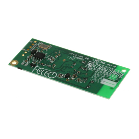
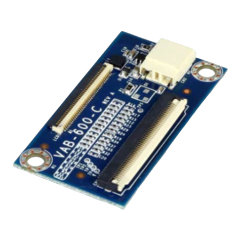
The VAB-600-B is an USB connectivity module equipped with four
9-pins C M connectors, and it is specially designed to provide
additional C M ports to VAB-600-B Pico-ITX mainboard. Each C M
connector is used to attach C M cable ports (male DE-9 connec-
tor) that supports RS-232 standard. The VAB-600-B module can be
installed to VAB-600 mainboard through onboard mini-card slot.
Top View
Top ViewTop View
Top View
Side View
Side ViewSide View
Side View
Bottom View
Bottom ViewBottom View
Bottom View
C M 3 connector: CN3
C M 3 connector: CN3C M 3 connector: CN3
C M 3 connector: CN3
C M 4 Connector: CN4
C M 4 Connector: CN4 C M 4 Connector: CN4
C M 4 Connector: CN4
Pin
PinPin
Pin
Signal
SignalSignal
Signal
Pin
PinPin
Pin
signal
signalsignal
signal
1 DCD_3 6 DSR_3
2 RXD_3 7 RTS_3
3 TXD_3 8 CTS_3
4 DTR_3 9 RI_3
5 GND
Pin
PinPin
Pin
Signal
SignalSignal
Signal
Pin
PinPin
Pin
signal
signalsignal
signal
1 DCD_4 6 DSR_4
2 RXD_4 7 RTS_4
3 TXD_4 8 CTS_4
4 DTR_4 9 RI_4
5 GND
Installing VAB-600-B
to VAB-600 mainboard
Step 1
Step 1Step 1
Step 1
To connect the VAB-600-B module to VAB-600 mainboard, align
the notch of module with the notch on Mini-card slot. Then gently
insert the module into the mini-card slot at a 20 degrees angle.
Step 3
Step 3Step 3
Step 3
Secure the module with a 6mm screw to the standoff.
Top Golden Finger: J1
Top Golden Finger: J1Top Golden Finger: J1
Top Golden Finger: J1
Pin
PinPin
Pin
Signal
SignalSignal
Signal
1 -
3 -
5 -
7 CLKREQ-
9 GND
11 -
13 -
15 GND
17 -
Pin
PinPin
Pin
19
21
23
25
27
29
31
33
35
Signal
SignalSignal
Signal
-
GND
-
-
GND
GND
-
-
GND
Pin
PinPin
Pin
37
39
41
43
45
47
49
51
Signal
SignalSignal
Signal
GND
VSUS33
VSUS33
GND
-
-
-
-
Golden Finger Pinouts
2 Bottom Golden Finger: J1
Bottom Golden Finger: J1Bottom Golden Finger: J1
Bottom Golden Finger: J1
Pin
PinPin
Pin
Signal
SignalSignal
Signal
2 VSUS33
4 GND
6 -
8 -
10 -
12 -
14 -
16 -
18 GND
Pin
PinPin
Pin
20
22
24
26
28
30
32
34
36
Signal
SignalSignal
Signal
-W_DISABLE_1
PEX1_RST
VSUS33
GND
-
I2C0SCL
I2C0SDA
GND
USBHD_0-
Pin
PinPin
Pin
38
40
42
44
46
48
50
52
Signal
SignalSignal
Signal
USBHD_0+
GND
LED_WWAN-
LED_WLAN-
LED_WPAN-
-
GND
VSUS33
Step 2
Step 2Step 2
Step 2
nce the module has been fully inserted, push down the rear side
of the module until the screw hole is aligned and seated on the
standoff mounting hole of the mainboard.
Step 4
Step 4Step 4
Step 4
Gently connect the C M cable ports to the C M onboard
connector.
3

Other VIA Technologies Control Unit manuals

VIA Technologies 40 User manual

VIA Technologies

VIA Technologies 40 User manual

VIA Technologies SOM-6X80 User manual

VIA Technologies

VIA Technologies SOM-6X80 User manual

VIA Technologies VAB-600-C User manual

VIA Technologies

VIA Technologies VAB-600-C User manual

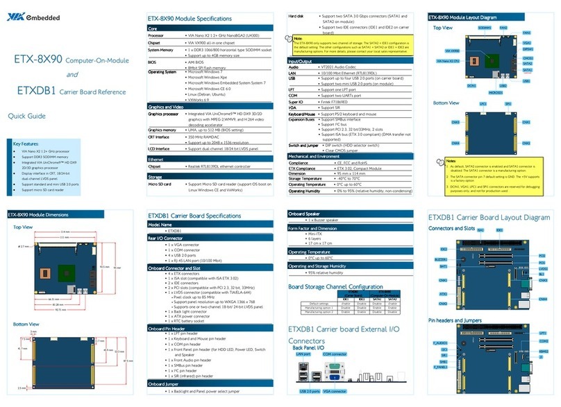
VIA Technologies ETX-8X90 User manual

VIA Technologies

VIA Technologies ETX-8X90 User manual

VIA Technologies VNT6656GUV00 User manual

VIA Technologies

VIA Technologies VNT6656GUV00 User manual

VIA Technologies VNT9271BB05B User manual

VIA Technologies

VIA Technologies VNT9271BB05B User manual

VIA Technologies SOM-9X35 Guide

VIA Technologies

VIA Technologies SOM-9X35 Guide

VIA Technologies WMP-G10 User manual

VIA Technologies

VIA Technologies WMP-G10 User manual

VIA Technologies COMe-8X91 User manual

VIA Technologies

VIA Technologies COMe-8X91 User manual

VIA Technologies VAB-3000 User manual

VIA Technologies

VIA Technologies VAB-3000 User manual

VIA Technologies SOM-9X35-STK User manual

VIA Technologies

VIA Technologies SOM-9X35-STK User manual

VIA Technologies VNT6656G6A10 User manual

VIA Technologies

VIA Technologies VNT6656G6A10 User manual

VIA Technologies QSM-8Q60 User manual

VIA Technologies

VIA Technologies QSM-8Q60 User manual

VIA Technologies SOM-3000-STK User manual

VIA Technologies

VIA Technologies SOM-3000-STK User manual

VIA Technologies QSM-8Q60 User manual

VIA Technologies

VIA Technologies QSM-8Q60 User manual

VIA Technologies VX800 Series Owner's manual

VIA Technologies

VIA Technologies VX800 Series Owner's manual

VIA Technologies ETX-8X90 User manual

VIA Technologies

VIA Technologies ETX-8X90 User manual

Popular Control Unit manuals by other brands

Elfa 75-576-22 manual

Elfa

Elfa 75-576-22 manual

Fracarro 3DGFLEX operating instructions

Fracarro

Fracarro 3DGFLEX operating instructions

Beninca THINK manual

Beninca

Beninca THINK manual

vacuubrand VKW-B Instructions for use

vacuubrand

vacuubrand VKW-B Instructions for use

Cabletron Systems MCC-DFL quick reference

Cabletron Systems

Cabletron Systems MCC-DFL quick reference

DSE DSE2157 installation instructions

DSE

DSE DSE2157 installation instructions

Compur Statox 503 Getting started

Compur

Compur Statox 503 Getting started

ASCOM teleCARE installation instructions

ASCOM

ASCOM teleCARE installation instructions

Siemens SENTRON Series operating instructions

Siemens

Siemens SENTRON Series operating instructions

roco 10777 manual

roco

roco 10777 manual

Festo CPX-FVDA-P2 Operating	 instruction

Festo

Festo CPX-FVDA-P2 Operating instruction

MOGAS T Series Installation, operation and maintenance manual

MOGAS

MOGAS T Series Installation, operation and maintenance manual

Numato AD9763 user guide

Numato

Numato AD9763 user guide

quiko QK-CE220WRL quick start guide

quiko

quiko QK-CE220WRL quick start guide

Renishaw HSI quick start guide

Renishaw

Renishaw HSI quick start guide

Task Force Tips Max Flip Tip2 manual

Task Force Tips

Task Force Tips Max Flip Tip2 manual

Burkert 6213 operating instructions

Burkert

Burkert 6213 operating instructions

Waldmann TALK EnOcean operating manual

Waldmann

Waldmann TALK EnOcean operating manual

manuals.online logo
manuals.online logoBrands
  • About & Mission
  • Contact us
  • Privacy Policy
  • Terms and Conditions

Copyright 2025 Manuals.Online. All Rights Reserved.