ViaSat Business Voice User manual

Business Voice
Installation Guide

Viasat Business Hotspots Installation Guide
Page | 2
Contents
Voice network installation ............................................................................................................................................ 3
Equipment....................................................................................................................................................................... 4
Network connections ................................................................................................................................................ 5
Required for installation .......................................................................................................................................... 5
Installation instructions ........................................................................................................................................... 6
Step 1 | Ensure all tools, equipment, and supplies are included.......................................................... 6
Step 2 | Determine equipment location.......................................................................................................... 6
Step 3 | Install Viasat Satellite solution ......................................................................................................... 6
Step 4 | Set up phone ............................................................................................................................................ 6
Step 5 | Install BLF paper label ........................................................................................................................ 7
Step 6 | Install CAT5E cable ............................................................................................................................... 8
Step 7 | Connect the handset ............................................................................................................................. 8
Step 8 | Install network equipment ................................................................................................................. 9
Step 9 | Basic network troubleshooting ...................................................................................................... 10
Step 10 | Complete documentation ............................................................................................................... 10
Step 11 | Review Quick Start Guide with customer ................................................................................... 11
Terminating UTP cable ................................................................................................................................................ 12

Viasat Business Hotspots Installation Guide
Page | 3
Voice Network Installation

Viasat Business Hotspots Installation Guide
Page | 4
Equipment
The equipment shown below will be installed at the customer site.
Satellite antenna Satellite modem PoE injector
Controller IP phone*
Blue Ethernet patch cable Green Ethernet patch cable
*Up to 4 units; includes handset, phone cord, phone stand / wall mount, and BLF labels.

Viasat Business Hotspots Installation Guide
Page | 5
Network connections
Required for installation
The following tools, safety equipment, and supplies are required for installation:
Tools Safety equipment
1 – Power/impact drill 1 – Hard hat
1 – RJ45/coaxial cable prep tool 1 – Safety Glasses
1 – Linear compression tool 1 – Safety vest
1 – Screwdriver (flat head) 1 – Gloves
1 – Screwdriver (Phillips head)
1 – Tape measure Supplies
1 – 5/8in paddle bit CAT5e color-coded Ethernet cables (included)
1 – Ladder CAT5e black standard Ethernet cable
1 – Laptop or smartphone Cable clips
1 – Cat5E cable tester RJ45 connectors

Viasat Business Hotspots Installation Guide
Page | 6
Installation instructions
This installation guide provides comprehensive instructions for equipment installation and documentation when
adding the Business Voice network to the Viasat Satellite Internet solution.
Step 1 | Ensure all tools, equipment, and supplies are included
Double check all equipment to ensure all parts, tools, equipment, spares, and anything needed for a successful
installation are included prior to departing for the location.
Step 2 | Determine equipment location
Select a cool, dry, secure location near a power source for installing the satellite modem, controller, and PoE
injector/s.
Discuss with the customer where they want the phone/s to be installed.
Step 3 | Install Viasat satellite solution
Using the installation requirements designated by Viasat in the Installation and Service Call Standards document,
install the Viasat Satellite solution.
Step 4 | Set up phone
Phone stand
1
Insert the hooks on top of the stand into the slots using either upper or lower slots.
2
Firmly slide the stand upward to lock it in place.

Viasat Business Hotspots Installation Guide
Page | 7
Wall mount
1
Attach the wall mount (inverted stand) to the wall using screws.
2
Slide the wall mount up and pull away from the wall over the screws to remove.
3
With the wider end of the stand at the bottom, insert all four hooks located in the front of the
wall mount into the slots on the back of the phone.
4
Firmly slide the wall mount upward to lock it in place.
5
Pull out and rotate the tab from the handset rest to hold the handset while the phone is
mounted on the wall.
6
Place the wall mount over the screws and slide down to secure.
Step 5 | Install BLF paper label
1
Align the cutouts on the paper label with the plastic notches on the phone and gently lay the paper down on
the phone surface.
2
Install the plastic cover over the paper label by inserting the non-cutout side of the panel. Adjust the plastic
cover in an up/down direction to make the three cutouts on the right side align with the plastic notches.
3
Slightly pull the plastic cover upward.

Viasat Business Hotspots Installation Guide
Page | 8
Step 6 | Install Cat5e cable
For each IP phone, cut to length (1) standard Cat5e Ethernet cable from the controller to the location the phone will
be installed. Terminate the ends and test each cable with a Cat5e cable tester.
NOTE: Wait to tie down the cables until after all equipment is installed and tested.
Step 7 | Connect the handset
1
Connect one end of the phone cord to the handset.
2
Connect the other end of the phone cord to the handset port on the back of the phone.

Viasat Business Hotspots Installation Guide
Page | 9
Step 8 | Install network equipment
Install the satellite modem, controller, and PoE injector/s in a secure location near a power outlet.
Modem to controller
1
Place the controller near the satellite modem.
2
Connect the blue Ethernet patch cable from the
modem to Port 1 on the controller.
3
Then plug in the power cables from the modem and
controller into the power source.
Controller to PoE injector
1
Connect one end of a green Ethernet patch cable into
one of Ports 6-9 on the controller.
2
Then connect the other end into the LAN port on the
PoE injector. Repeat this step for each additional IP
phone.
PoE injector to IP phone
1
Connect one end of the standard Ethernet cable into
the POE port on the PoE injector.
2
Then connect the other end the cable into the LAN port
on the back of the IP phone.
3
Plug the PoE injector into the power source.
4
Repeat this step for each additional PoE injector used
for the IP phones.
Auto-provisioning
When connected to power and internet (data), the phone
screen will display provisioning or firmware upgrade
information. The phone will reboot several times during
this process.
The provisioning process takes approximately 8-10
minutes. Once complete, the date and time, phone
number, and network status icon appear on the screen.
NOTE: Do not interrupt the power or internet connection
when the LED lights are flashing during system boot up
or firmware upgrade, as this may corrupt firmware
images and cause the unit to malfunction.
WARNING! If the power adapter for the phone was not removed prior to shipment, please remove it and do
not provide it to the customer. If the power adapter is used in conjunction with the PoE Injector, it will damage
the phone and could pose a potential fire hazard.

Viasat Business Hotspots Installation Guide
Page | 10
Step 9 | Basic network troubleshooting
Basic troubleshooting
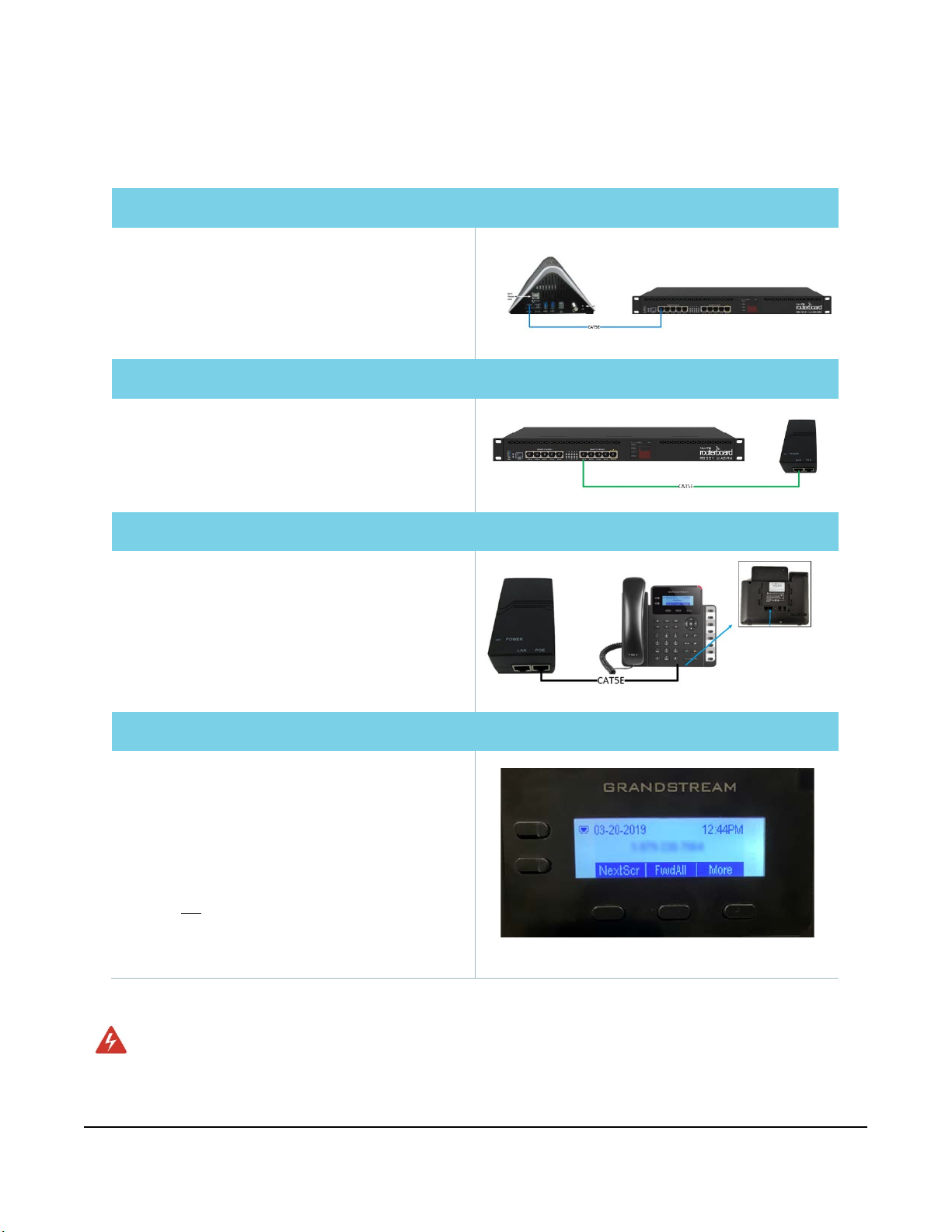
Phone will not
provision
›Reboot the phone by unplugging the Ethernet cable and plugging it back in.
›If that doesn’t resolve the issue, reset the phone:
•Press the menu button.
•Scroll down to system and select.
•Scroll down to factory reset and select.
•Select ok softkey to confirm.
•Select ok softkey to confirm again.
•The phone should reset and start the auto-provisioning process again.
Phone will not register ›Contact installer Relations at (855) 632-5063. Provide the MAC address of the phone to
determine if the correct MAC address was associated with the phone number.
Step 10 | Complete documentation
The installation is not complete until all points of the installation have been documented in LiveQC, a video chat
service that is accessed through FSTechSupport, available in the Android and Apple app stores.
1
Log in to the FSTechSupport app using your tech ID and password.
2
Enter the job number and select LiveQC to be placed in queue for the next available agent.
3
The agent will request the FSM ID, Tech ID, customer name, address and phone number, service region,
account number, work order type, and work order close reason.
4
Next the agent will request video inspection of different aspects of the installation to indicate on their form if
it passes, fails, or is not applicable. See the table below for information requested by the agent.
Included in LiveQC inspection
›Mount type (roof, round pole, wall, stubby,
hexpole, or S-mount)
›If the mount is an approved type
›Antenna pointing
›Line of sight
›Approved cable use and aesthetics
›Equipment (cable and ODU)
›ODU mount and hardware
›System grounded to NEC ground source
If the technician followed proper procedures:
›Pre-install customer experience procedures
›Antenna assembly
›Cable routing
›System pointing and peaking
›Post-install customer experience procedures
›Antenna mount
›System grounding
›System provisioning
5
Finally, pictures will be uploaded to LiveQC:
Upload pictures
›Location
›Line of sight
›Back assembly
›Mount
›Ground source
›Ground block
›Ground run
›Cable run
›Cable type
›Point of entry
›Hole depth
›Pole height
›Bonding point
›Any other requested images
6
Any additional notes or comments may be added as needed.

Viasat Business Hotspots Installation Guide
Page | 11
Step 11 | Review Quick Start Guide with customer
A Business Voice Quick Start Guide for the customer is included with the network equipment. Review the guide with
the customer to ensure they are aware of key information about their voice network:
›Basic features of the service
›Basic functions of the phone and keypad
›How to access the web GUI to add speed dial and select headset type
›How to access the Viasat Voice Pro mobile dialer
›How to contact customer support
Need help? Contact Viasat Installer Relations at (855) 632-5063.

Viasat Business Hotspots Installation Guide
Page | 12
Terminating UTP cable

Viasat Business Hotspots Installation Guide
Page | 13
This section outlines step-by-step procedures for terminating UTP cable using a crimping tool, UTP cable stripper,
and an RJ45 connector. Also see the Ethernet Cable Prep Job Aid located in the
eGuide
.
Step 1: Trim cable
Using a Crimping Tool, trim the end of the cable
you're terminating to ensure that the ends of the
conducting wires are even.
Step 2: Strip jacket
Being careful not to damage the inner conducting
wires, strip off approximately 1 inch of the cable's
jacket, using a modular crimping tool or a UTP
cable stripper.
Step 3: Separate wires
Separate the 4 twisted wire pairs from each other,
and then unwind each pair, so that you end up
with 8 individual wires. Flatten the wires out as
much as possible, since they'll need to be very
straight for proper insertion into the connector.
Step 4: Arrange wires
Holding the cable with the wire ends facing away
from you. Moving from left to right, arrange the
wires in a flat, side-by-side ribbon formation,
placing them in the following order: white/orange,
solid orange, white/green, solid blue, white/blue,
solid green, white/brown, solid brown.
Terminating UTP cable

Viasat Business Hotspots Installation Guide
Page | 14
Step 5: Insert wires
Holding the RJ45 connector so that its pins are
facing away from you and the plug-clip side is
facing down, carefully insert the flattened,
arranged wires into the connector, pushing
through until the wire ends emerge from the pins.
For strength of connection, also push as much of
the cable jacket as possible into the connector.
Step 6: Confirm proper formation
Check to make sure that the wire ends coming out
of the connector's pin side are in the correct
order; if not, remove them from the connector,
rearrange into proper formation, and re-insert.
Remember, once the connector is crimped onto
the cable, it's permanent. If you realize that a
mistake has been made in wire order after
termination, you'll have to cut the connector off
and start all over again.
Step 7: Crimp plug
Insert the prepared connector/cable assembly
into the RJ45 slot in your crimping tool. Firmly
squeeze the crimper's handles together until you
can't go any further. Release the handles and
repeat this step to ensure a proper crimp.
Step 8: Repeat
After the first termination is complete, repeat
process on the opposite end of your cable.
View online at http://www.cableorganizer.com/learning-center/how-to/how-to-terminate-RJ45.htm
Table of contents
Popular Telephone System manuals by other brands

Homeworks
Homeworks HWI-TEL9 Instructions for installation and use

NEC
NEC NDK 9000 Operations

CBTS
CBTS ONX Hosted UC installation manual

Avaya
Avaya IP Office Essential Edition PARTNER Version Reference manual

GAI-Tronics
GAI-Tronics TI984 user manual

Unifone
Unifone Small Office Installation and programming manual