Copyright © VibroSystM Inc., 2010 iii
OPCS-200ESB Measuring Chains with LIN-300 Series Signal Conditioner_TOC
TABLE OF CONTENTS
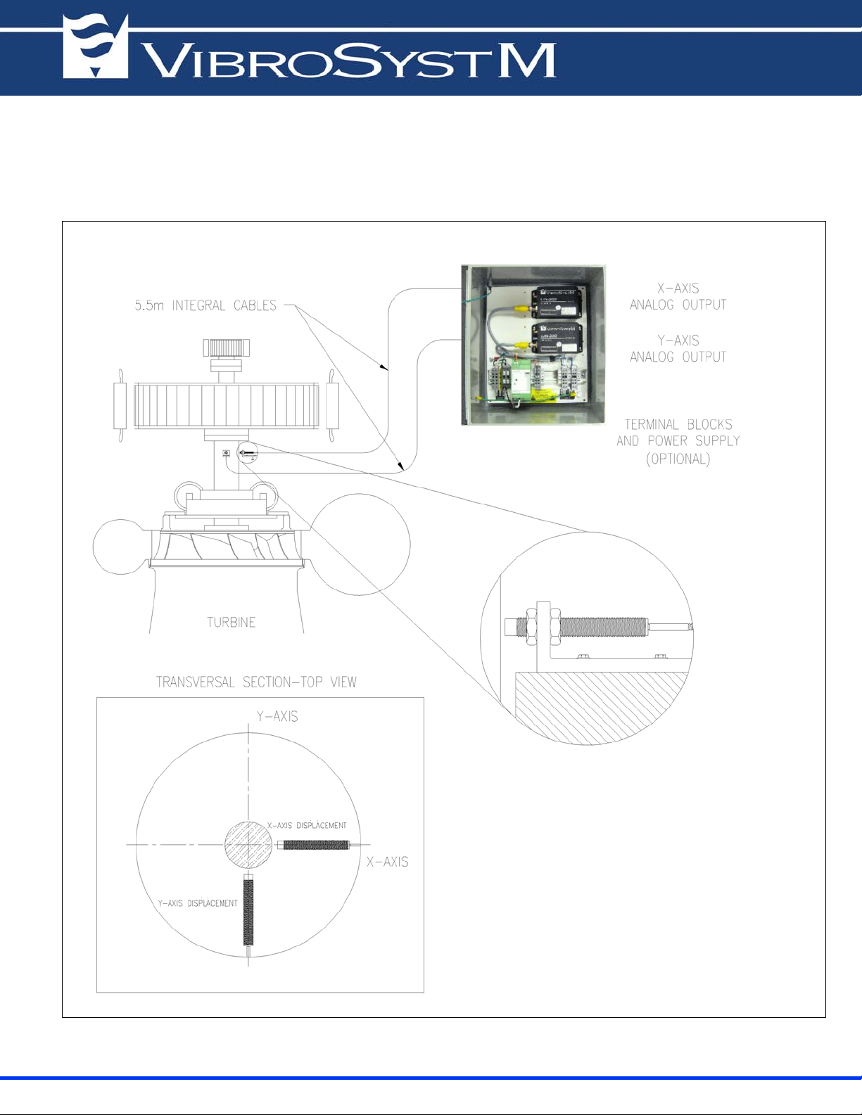
1. OVERVIEW OF THE PCS-200ESB MEASURING CHAINS
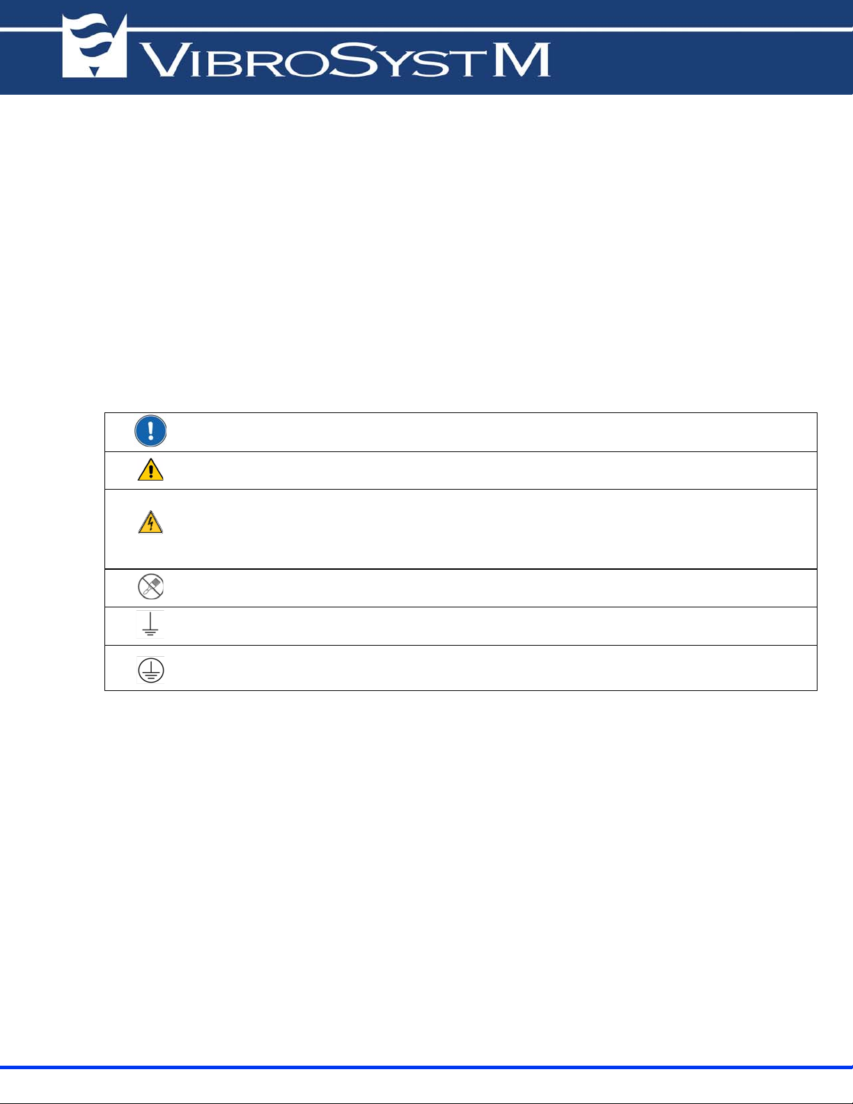
1.1 Safety information................................................................................................................................. 6
1.2 Planning and installation requirements.................................................................................................. 7
1.3 General specifications of measuring chains .......................................................................................... 8
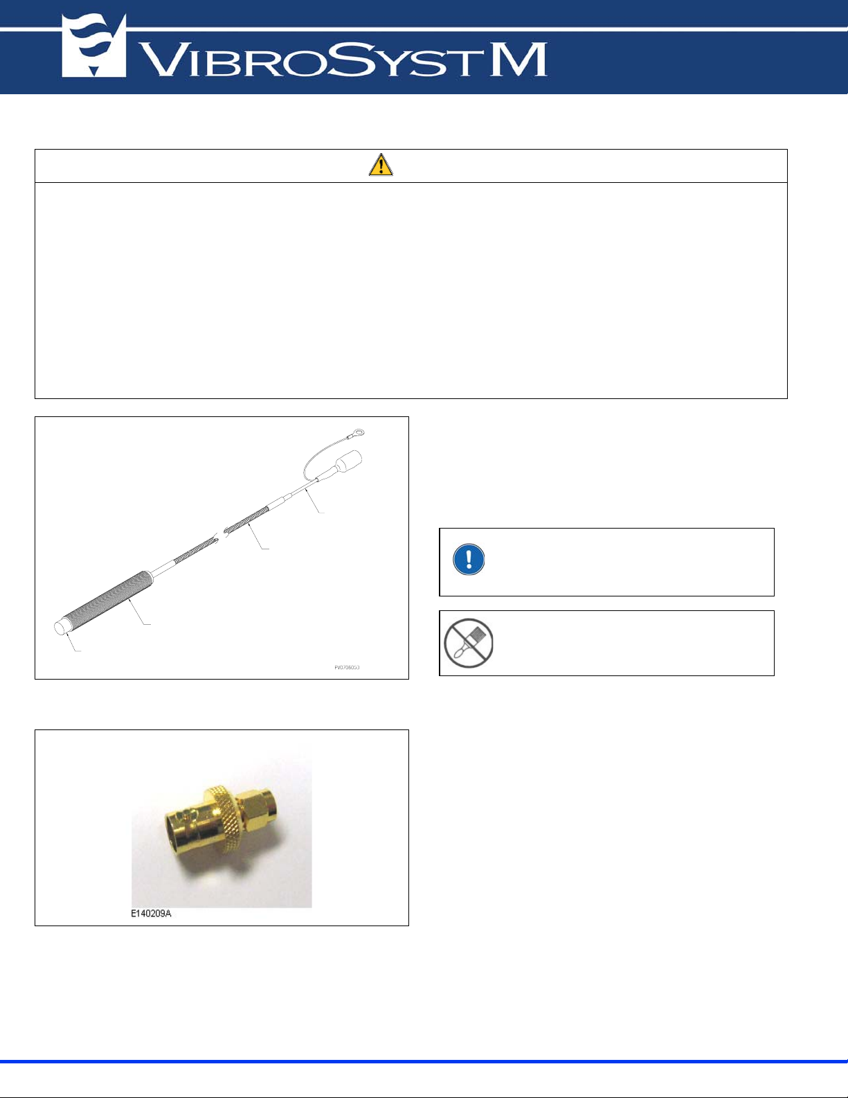
2. INSTALLATION OF THE PCS-200ESB PROXIMITY SENSOR
2.1 Preliminary considerations.................................................................................................................... 9
2.1.1 Supplies needed........................................................................................................................ 11
2.1.2 Tools needed............................................................................................................................. 11
2.2 Step by step installation of the PCS-200SB sensor............................................................................... 11
2.2.1 Choosing the sensors location.................................................................................................. 11
2.2.2 Machining of mounting brackets.............................................................................................. 12
2.2.3 Installating mounting brackets and sensors.............................................................................. 13
2.2.3.1 Sensor installation on an insulated bearing.............................................................. 14
2.2.4 Routing and clamping the integral cable.................................................................................. 15
2.3 General specifications of the PCS-200ESB sensor ............................................................................... 16
3. INSTALLATION OF THE LIN-300 PROTECTION BOXES
3.1 Installation of the 10X6X3 ABS Protection Box .................................................................................. 17
3.1.1 Preliminary considerations....................................................................................................... 17
3.1.2 Installation of the Protection Box............................................................................................. 18
3.1.3 Supplies needed........................................................................................................................ 18
3.1.4 Tools needed............................................................................................................................. 18
3.1.5 Preparing the holes for the liquidtight connectors.................................................................... 19
3.1.6 Fastening the protection box .................................................................................................... 20
3.2 Installation of the 14 x 12 x 8 Metal Protection Box............................................................................. 22
3.2.1 Preliminary considerations....................................................................................................... 22
3.2.2 Installation of the Protection Box............................................................................................. 23
3.2.3 Supplies needed........................................................................................................................ 23
3.2.4 Tools needed............................................................................................................................. 23
3.2.5 Preparing the holes for the liquidtight connectors and grounding assembly............................ 24
3.2.6 Fastening the protection box .................................................................................................... 26
3.2.7 Grounding the protection box................................................................................................... 28
4. INSTALLATION OF LIN-300 SERIES MODULES
4.1 Preliminary considerations.................................................................................................................... 31
4.1.1 Supplies needed........................................................................................................................ 32
4.1.2 Tools needed............................................................................................................................. 32