vi •XX091-04-01 Rev 104 AurorAcorD
* * * * * * * * * * * * * * *
* * * * * * * * * * * * * * *
* * * * * * * * * * * * * * *
– – – – – – – – – – – – – – –
* * * * * * * * * * * * * * *
* * * * * * * * * * * * * * *
* * * * * * * * * * * * * * *
* * * * * * * * * * * * * * *
* * * * * * * * * * * * * * *
* * * * * * * * * * * * * * *
* * * * * * * * * * * * * * *
* * * * * * * * * * * * * * *
to choose a row.
1-16 to turn zone On/Off.
ZOOM+/ZOOM– row On/Off.
to test zone activity.
to Go Back.
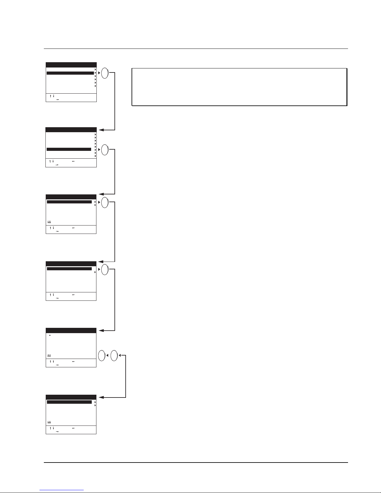
MOTION ZONE SETUP
1 Next Easy Menu
2 Title: CAMERA 01
3 Alarm Pin: In/Norm. Open
4 Update Priority: High
5 Camera Motion Setup
CAMERA 1 EASY MENU
to Choose. to Go Back.
or 1-16 to Select.
1 Camera Number: 1
2 Camera Title: Camera 01
3 Motion: Higher Update
4 Detection Threshold: 2
5 Min Active Zones: 8
6 Motion Zone Setup
CAMERA MOTION SETUP
to Choose. to Go Back.
or 1-16 to Select.
LIVE
PLAY
PLAY
7. The Motion field on the Camera Motion Setup is used to
define what will happen when motion is detected: Alarm
+ Higher Update (update rate for the live video on the
main display monitors increases and an alarm is
activated), Disabled: (no action occurs), Alarm (an alarm
is activated), Higher Update (update rate for live video on
the main display monitors increases). Decide which
choice above is required for detected motion on this
camera and make the selection using the onscreen
instructions.
8. The detection threshold defines the change in video level
required before motion is detected. The settings are 1 to
9. At a setting of 9, a dramatic change in video level is
required to trigger motion detection. The most sensitive
setting is 1. Each camera has its own detection threshold,
so that cameras in high security areas may be set to
detect movement by more stringent guidelines than
cameras in less important viewing areas. Define the
Detection Threshold for this camera.
9. The Minimum Active Zones field defines the minimum
number of zones that must be active before motion is
detected. For example, if the minimum number of active
zones is set to 14, then 14 zones must pass the detection
threshold before the AurorAcorD has detected motion.
Make your selection and then access the Motion Zone
Setup screen.
10. This screen is used to turn on (enable) or turn of
(disable) motion detection in each of the zones in a
camera’s field of view. For example, it would be practical
to disable the motion detection zones corresponding to
trees blowing outside a window, a fan on the wall or a TV
screen. The first step in setting the zones is to direct the
camera to its normal position. Viewing the scene on the
monitor, decide which zones should be enabled o
disabled. Zones are represented onscreen by individual
boxes on the grid. An asterisk represents an enabled
zone; blank zones are disabled. Use the up/down arro
keys to select a row and then use the 1-16 keys to
enable/disable the zones in that row. Use the Zoom +/-
keys to enable/disable entire rows at once.
11. After defining the zones, press Play to test your zones b
activating alarms in the active areas. The detection
threshold number for each zone will display onscreen fo
detected motion. This allows you to decide if the detection
threshold that you set in the previous screen is
appropriate. If you are satisfied with the results of this
test, use the left arrow key to return to the Camera Motion
Setup screen. Repeat this procedure for each camera in
your system. If the results of this simulation do not satisf
the requirements of motion detection for this camera,
redefine your detection threshold (and enable/disable
more zones, if necessary) and then test again.
12. Press the Live key twice to return to the Camera 1 Eas
Setup Menu. Select Next Easy Menu and repeat the
camera configuration procedure to define the next
camera until all cameras are defined.