Vicon V1400X-MSSV User manual

Vicon Part No. 8009-8055-01-00 Section 9 Rev 1201
XX055-01-00
V1400X-MSSV Multisystem Selector
Vicon Industries Inc. does not warrant that the functions contained in this equipment will meet your requirements
or that the operation will be entirely error free or perform precisely as described in the documentation. This
system has not been designed to be used in life-critical situations and must not be used for this purpose.
Copyright © 2001 Vicon Industries Inc. All rights reserved.
Product specifications subject to change without notice.
NOVA and its logo are trademarks of Vicon Industries Inc.
Vicon and its logo are registered trademarks of Vicon Industries Inc.
VICON INDUSTRIES INC., 89 ARKAY DRIVE, HAUPPAUGE, NEW YORK 11788
TELEPHONE: 631-952-CCTV (2288) FACSIMILE: 631-951-CCTV (2288)
24-Hour Technical Support: 800-34-VICON (800-348-4266)
TOLL FREE: 800-645-9116 UK: 44/(0) 1489-566300 INFOFAX: 800-287-1207


XX055-01-00 Rev 1201 V1400X-MSSV Multisystem Selector Contents •
••
•i
Contents
INTRODUCTION .......................... 1
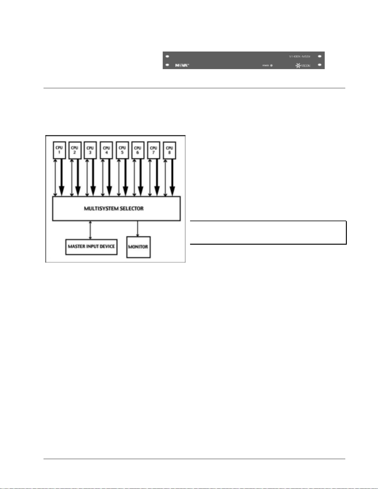
V1400X-MSSV Multisystem Selector............................................................................................................ 1
INSTALLATION................................................................................................................... 2
Quick Installation........................................................................................................................................... 2
Unpacking and Inspection............................................................................................................................ 3
Physical Installation ...................................................................................................................................... 3
Accessory Kit................................................................................................................................................ 3
Desk Mount............................................................................................................................................... 3
Rack Mount............................................................................................................................................... 3
Cabling............................................................................................................................................................ 3
Power Connection........................................................................................................................................ 3
CPU Connection .......................................................................................................................................... 4
Master Input Device Connection.................................................................................................................. 4
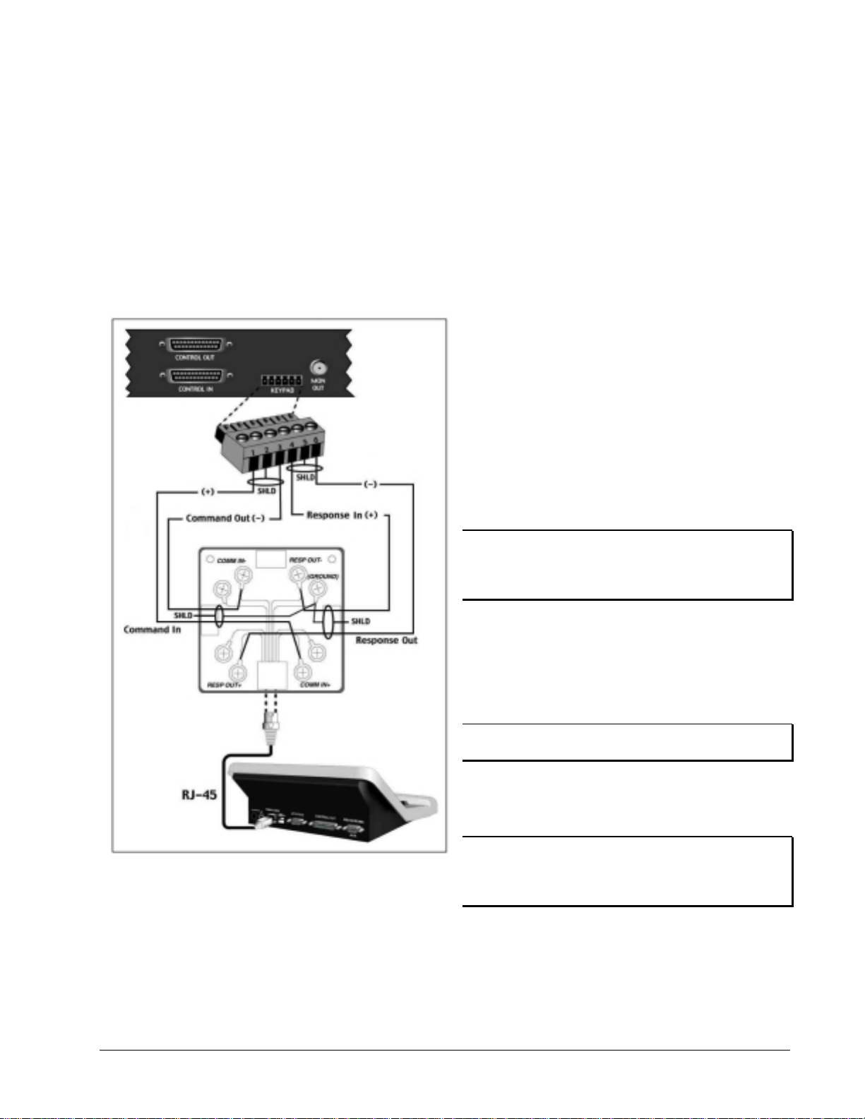
V1300X-DVC/V1300X-RVC Keypads ...................................................................................................... 4
Keypad Connection............................................................................................................................... 4
SHD Adapter/37-Pin Cable................................................................................................................... 5
V1400X-DVC System Console................................................................................................................. 6
Keypad Connection............................................................................................................................... 6
25-Pin Cable ......................................................................................................................................... 6
OPERATION........................................................................................................................ 8
Requirements and Characteristics .............................................................................................................. 8
Addressing ................................................................................................................................................... 8
CPU.............................................................................................................................................................. 8
V1300X-DVC/RVC Requirements and Characteristics............................................................................... 8
Basics........................................................................................................................................................... 8
Firmware ...................................................................................................................................................... 8
Program Message........................................................................................................................................ 8
CPU.............................................................................................................................................................. 8
Applications ................................................................................................................................................... 9
Operation Verification Procedure .............................................................................................................. 10
V1300X-DVC/V1300X-RVC Keypads........................................................................................................ 10
V1400X-DVC System Console .................................................................................................................. 11
CPU Control System Operation.................................................................................................................. 12
MAINTENANCE................................................................................................................. 13

XX055-01-00 Rev 1201 V1400X-MSSV Multisystem Selector Contents •
••
•ii
Fuse Replacement....................................................................................................................................... 13
SHIPPING INSTRUCTIONS............................................................................................... 14
REFERENCE ..................................................................................................................... 15
Coaxial Cable ............................................................................................................................................... 15
Cable Recommendations............................................................................................................................ 16
RS-422/485 Protocol.................................................................................................................................. 16
Control Signals........................................................................................................................................... 16
Manual References for Associated Equipment ........................................................................................ 17
CPUs.......................................................................................................................................................... 17
Input Devices.............................................................................................................................................. 17
TECHNICAL INFORMATION............................................................................................. 18
ELECTRICAL.......................................................................................................................................... 18
CONTROLS & CONNECTORS.............................................................................................................. 18
OPERATIONAL...................................................................................................................................... 19
MECHANICAL........................................................................................................................................ 19
ENVIRONMENTAL................................................................................................................................. 19

XX055-01-00 Rev 1201 V1400X-MSSV Multisystem Selector Introduction •
••
•1
Introduction
V1400X-MSSV Multisystem Selector
This manual covers the installation and operation of the Vicon V1400X-MSSV Multisystem Selector. The
installation procedures should only be performed by a qualified technician using approved materials in
accordance with national, state and local wiring codes. Read these instructions completely before attempting
installation.
The Selector provides convenient control of up to 8
Vicon CPU-based controls and matrix systems via a
Vicon input device (Keypad, System Console, etc.
Keypads, System Consoles or other control units will be
referred to as “Input Device” throughout this manual.
Each CPU is controlled using standard Vicon RS-
422/485 protocol on a 9-pin D-shell connector. Each
Input Device is connected using RS-422/485 protocol
and additional digital signals on a 25-pin D-shell
connector. The Selector provides full video following for
CPU identification.
NOTE: RS-422 and RS-485 are industry standard data
transmission protocols used for external device
communication in this unit.
An added feature of the Selector is the ability to add
slave Input Devices for additional control of a CPU.
Figure 1 shows the Basic System Setup, which is
comprised of a Selector, multiple CPUs and a Master
Input Device and a Monitor.
In addition to the Selector, this manual provides abbreviated descriptions of Vicon Input Devices, as the
operation of the Selector relies solely on the input device. There are variations in configurations that include
the use of a Distribution Control Unit, which are described later.
Refer to the "Manual References for Associated Equipment" section, at the back of this manual, for specific
peripheral equipment installation and operation instructions.
The Selector is available in two versions, Model V1400X-MSSV (120 VAC) and Model V1400X-MSSV-230
(230 VAC). The 230 VAC model is equipped with the correct molded plug on the line cord.
Figure 1
Basic System Setup

XX055-01-00 Rev 1201 V1400X-MSSV Multisystem Selector Installation •
••
•2
Installation
Installation of the Selector is simple. This Section will detail complete installation that is comprised of Physical
Installation and Cabling sub-sections.
Quick Installation

XX055-01-00 Rev 1201 V1400X-MSSV Multisystem Selector Installation •
••
•3
Unpacking and Inspection
All Vicon equipment is tested and inspected before leaving the factory. It is the carrier’s responsibility to
provide suitable delivery. Inspect the cartons upon delivery and, if damage is present, make detailed notes on
the carrier’s bill. Obtain the carrier agent’s signature and file a damage claim as soon as possible.
Open the cartons and inspect the equipment for damage. Save the cartons and packing material. If damage is
present, contact the carrier and file a damage claim immediately. If the equipment must be returned to Vicon
for repair, follow the instructions in the Shipping Information Section of this manual.
Physical Installation
The Selector is designed for desk-top use or for installation in an EIA standard 19-inch (483 mm) instrument
rack. In rack installation, it is important that approximately 1.75 inch (45 mm) of space is left between each
rack-mounted unit for ventilation. This spacing also provides easier access to equipment rear panels.
Accessory Kit
An Accessory Kit is provided which includes 4 rubber feet, 1 power cord with the correct molded plug, 9
Terminal Block Connectors, 1 37-pin female to 25-pin male adapter and 1 37-pin male to 37-pin male cable, 8
75-ohm terminators and rack mounting brackets with screws.
Desk Mount
The Selector can be used on a solid desk surface. Use the 4 rubber feet provided to make a stable base.
Attach an adhesive backed bumper to each corner of the bottom surface and press firmly.
Rack Mount
The Selector can be rack mounted using hardware supplied with the Rack. Place the Selector at the desired
Rack position and attach it using 4 appropriate bolts and nuts. No additional support is required.
Cabling
The Selector must be connected to power, CPU and Master Input Device controls. This sub-section will detail
complete cabling. Power Connection
The Selector is factory set for its operating voltage and requires only proper
use of the provided line cord.
NOTE: Do not insert the line cord plug into the Selector until all cabling has
been completed.
Verify that the correct fuse is installed in the Active Fuse Holder as shown in
Figures 2 and 3.
NOTE: Vicon strongly recommends the use of line conditioners, voltage
regulators and uninterruptible power supply systems (UPS) to prevent
voltage fluctuations that can affect operation and cause damage to the
equipment.
Figure 3
Rear Panel Power Block

XX055-01-00 Rev 1201 V1400X-MSSV Multisystem Selector Installation •
••
•4
CPU Connection
The Selector uses standard RS-422/485 protocol on connectors STAT1-STAT8 (2-piece, 6-pin Terminal
Block Connectors). Connect the wires to the screws on the provided Terminal Block Connectors using the pin
designations in Figure 4 for STAT1-STAT8. Refer to the applicable CPU Control System manual for Keypad
connector pin designations. Refer to the Reference Section of this manual for Table 1, Shielded, Dual
Twisted-Pair Cable Maximum Operating Distances.
The Selector also allows analog video from the selected CPU to be displayed on a local monitor by use of
BNC connectors MON1 - MON8. Connect each individual CPU Monitor Out signal to the rear panel MON
input using standard coaxial cable. Refer to the Reference Section of this manual for the Coaxial Cable sub-
section. 1. Insert the appropriate signal wires into the Terminal Block
Connector as defined in Figure 4. It is recommended to label
both cable ends (CPU end/MSSV end).
2. Connect the CPU end of the cable to the Keypad connector on
the CPU. Some assembly may be required for this connector.
3. Plug the wired Terminal Block Connector into the Selector's
Station 1 receptacle.
NOTE: Station 1 connector is used to represent any of the
Terminal Block Connectors STAT1-STAT8.
4. Connect additional CPU cables to consecutive Station
connectors (2 - 8).
5. Connect the coaxial cable between the CPU MON OUT
connector and the Selector's MON 1-8 input. Install a provided
BNC terminator, from the Accessory Kit, on unused MON
inputs.
Master Input Device Connection
The Selector uses standard RS-422/485 protocol on the Keypad connector (Terminal Block Connector) and
additional digital signals on the Control In Connector (25-pin D-shell type).
V1300X-DVC/V1300X-RVC Keypads
Keypad Connection
Wire one of the provided Terminal Block Connectors using the pin
designations in Figure 5 for the Keypad receptacle. Refer to the
Reference Section of this manual for Table 4, Shielded, Dual
Twisted-Pair Cable Maximum Operating Distances.
Figure 4
STAT1-STAT8 Pin Definition for CPU
Cable
Figure 5
Pin Definition for Master Input Device
Cable (Keypad)

XX055-01-00 Rev 1201 V1400X-MSSV Multisystem Selector Installation •
••
•5
SHD Adapter/37-Pin Cable
Use the provided SHD (Super-High-Density) Adapter (25-pin to 37-pin) and the 37-pin to 37-pin cable for the
Control signals. The SHD Adapter is simply a 2-connector converter of the Control signals from 25 pins to 37
pins. In the event that the Adapter is missing or damaged, fabricate a cable as shown in Figure 16 of the
Reference Section of this manual. 1. Insert the appropriate signal wires into
the Terminal Block Connector as
defined in Figure 5. It is recommended
to label both cable ends (Keypad
end/MSSV end).
2. Insert the appropriate signal wires into
the 12-pin Terminal Block Connector
for the Keypad, as shown in Figure 6.
3. Connect the Selector end of the cable
to the Keypad connector on the
Selector.
4. (Optional) Connect the Slave Keypads
as described in Vicon Installation and
Operation Manual X777.
5. Plug the wired 12-pin Terminal Block
Connector into the Keypad's J1
receptacle.
6. Connect the 25-pin side of the
provided SHD Adapter to the Control
In connector on the Selector's rear
panel, as shown in Figure 7.
NOTE: The Control Out connector on the
Selector is currently not used.
7. Connect one end of the 37-pin cable
to the 37-pin side of the SHD Adapter.
8. Connect the other end of the 37-pin
cable to the Aux connector (J20) on
the Master Keypad.
Figure 6
Pin Definition for Master Keypad Cable
Figure 7
Control In to J20 Cable Assembl
y

XX055-01-00 Rev 1201 V1400X-MSSV Multisystem Selector Installation •
••
•6
V1400X-DVC System Console
Keypad Connection
Wire one of the provided Terminal Block Connectors using the pin designations in Figure 8 for the Keypad
receptacle. The open wires are connected to the RJ-45 Termination Box and can be extended to 25,000 ft
(7600 m), depending on the cable type. Refer to the Reference Section of this manual for Table 4, Shielded,
Dual Twisted-Pair Cable Maximum Operating Distances. Use the RJ-45 to RJ-45 cable, provided with the
System Console, to connect between the Termination Box and the System Console.
25-Pin Cable
Use the provided 25-pin to 25-pin cable for the Control signals.
1. Insert the appropriate signal wires into the
Terminal Block Connector as defined in Figure
8. It is recommended to label both cable ends
(System Console end/MSSV end). Connect the
appropriate signal wires to the RJ-45
Termination Box screw terminals, as shown in
Figure 8.
2. Connect the Master System Console (RJ-45
connector) end of the RJ-45 to RJ-45 cable to
the Power/Comm connector on the Master
System Console, as shown in Figure 8.
NOTE: If the Power/Comm connector on the
System Console is currently wired for power, refer
to the unit's manual to rewire power into the
dedicated power connector.
3. Connect the other end of the RJ-45 cable (RJ-
45 connector) to the Termination Box.
4. Connect one end of the 25-pin cable to the
Control In connector on the Selector rear panel
as shown in Figure 9.
NOTE: The Control Out connector on the Selector
is currently not used.
5. Connect the other end of the 25-pin cable to
the Control Out connector (J2) on the Master
System Console.
NOTE: Refer to the System Console Instruction
Manual for information on daisy chaining additional
System Console units to the Master System
Console.
Figure 8
PWR/COMM Pin Definition for Master System
Console Cable

XX055-01-00 Rev 1201 V1400X-MSSV Multisystem Selector Installation •
••
•7
6. Attach the provided Power Cord to the Rear Panel Power Block. The Selector's Power LED should
illuminate indicating it is powered. In addition, the local monitor should display video of the currently
selected CPU.
Figure 9
Control In to Control Out Cable

XX055-01-00 Rev 1201 V1400X-MSSV Multisystem Selector Operation •
••
•8
Operation
The V1400X-MSSV Selector allows one or more Input Devices to control up to 8 different CPU-Based Matrix
Systems. Since the Selector does not have any panel controls, a Master Input Device (connected directly to
the Selector) is used for operation. Refer to Vicon Instruction Manuals for detailed information on the Keypads
and the System Console.
Requirements and Characteristics
Addressing
All Input Devices (Masters and Slaves) must have a unique address in the total system (no two Input Devices
should be addressed 1, for example). If 2 input devices share the same address, errors in communication will
occur. CPU
Some CPUs should have updated Firmware to work with the Selector. With the latest Firmware version, the
Selector will immediately switch between CPUs. The V1422 and V1466 CPUs are compatible, while the
V1300 and V1344 may require an update. With older revision Firmware, the Selector will have a 1-2 minute
pause. Some CPUs offer a Firmware setting to specify the status of on-line Input Devices. Set this to
ALWAYS ON.
V1300X-DVC/RVC Requirements and Characteristics
Basics
The Keypad can be switched to different CPUs by entering a four digit Camera number and pressing the CAM
button. In MSYS mode, the left most digit (thousands) represents system (CPU) addresses 1-8. The
remaining 3 digits represent normal camera selection. The CAMERA display now represents both CPU and
camera. To select system and camera, enter the system number first followed by camera number and press
the CAM button. Different cameras can be accessed using only the camera number (3 digits or less). For
example, to select, and display locally, the camera number 315 in system 3, enter 3315 and press the CAM
button. To select, and display, camera 25 in the same system, enter 25 and press the CAM button.
Firmware
The Master Keypad must have version 3.0 Firmware or later to operate with the Selector. The Firmware
version will flash across the Keypad STATUS display upon power-up. After setup, the STATUS display will
indicate “WAIT” with the current system number flashing in the left hand digit of the CAMERA display until the
CPU polls the Keypad. When communicating, the display will indicate “MSYS”.
Program Message
When the RUN/PGM switch is set to PGM position, a flashing PROG message will display in the STATUS
display. Move the switch to the RUN position to remove the message.
CPU
Some CPUs with older revision Firmware will delay in response to the Master Keypad. On initial start-up or
when switching CPUs, a message may appear on the Keypad about the CPU not responding. Ignore this
message and the Selector will eventually switch between CPUs.

XX055-01-00 Rev 1201 V1400X-MSSV Multisystem Selector Operation •
••
•9
Applications
Figure 10 shows the Selector with individual Station ports setup in 3 typical configurations using V1300X-
DVC/RVC Keypads as Input Devices. CPU 1 can be controlled from Keypads
1 and 3, not 2 and 4. CPU 2 can be
controlled from Keypads 1, 2 and 3, not
4. CPU 3 can be controlled from
Keypads 1, 3 and 4, not 2. In addition,
Keypad 3 can only control the system
selected by Keypad 1 (Master Keypad).
Keypads 2, 3 and 4 must be set for the
1300 mode, Keypad 1 for MSYS mode.
All four Keypads must have unique
addresses and be set to "always on" or
operation conflicts will occur.
Keypad Monitors 1 and 3 can view
CPUs 1, 2 or 3 simultaneously only.
Keypad Monitor 2 can view CPU 2 and
Keypad Monitor 4 can view CPU 3.
NOTE: Keypad 1 is the Master System
Keypad for the Selector.
Figure 11 shows the Selector with
individual Station ports setup in a
typical configuration using V1400X-
DVC System Consoles as Input
Devices.
The CPU can be controlled from
System Consoles 1 and 2. System
Console 2 can only control, through the
Failsafe Unit, the system selected by
System Console 1 (Master System
Console). Refer to Vicon's Instruction
Manual on the System Console for
connection details. Both System
Console units must have unique
addresses or operation conflicts will
occur.
Both System Consoles must view same
selected camera at all times.
NOTE: System Console 1 is the
Master System Console for the
Selector.
NOTE: Keypads and System Consoles
can be daisy chained together in the
same system.
Figure 10
Typical System Setup With V1300X-DVC/RVC Keypads
Figure 11
Typical System Setup With V1400X-DVC System Consoles

XX055-01-00 Rev 1201 V1400X-MSSV Multisystem Selector Operation •
••
•10
Operation Verification Procedure
V1300X-DVC/V1300X-RVC Keypads
Verify that all external equipment is powered-on and functional.
1. Place the Keypad ON/OFF switch, located on the rear panel, to the ON (I) position. The front panel
POWER LED should illuminate.
2. Setup the Master Keypad in accordance with Vicon Instruction Manual X777 using the following
parameters:
KEYPAD TYPE: MSYS
SPEED CONTROL TYPE: 1300
RECEIVER FUNCTION INHIBIT: NO
JOYSTICK RESPONSE: MED
BAUD RATE: 9.6 K
KEYPAD ADDRESS: (Next available in total system.)
MODIFY PASSCODE: NO
AUTO-LOGOUT: OFF
INSTALL DEFAULT PARAMETERS: NO
ENTER DIAGNOSTICS MODE?: (Press SEQ key to bypass.)
The STATUS display will indicate MSYS, which verifies communication between the Master Keypad and
Selector.
3. Key in MON, 1, MON, 1, CAM on the Keypad. The display reads as follows:
STATUS CAMERA MONITOR
MSYS 1…1 1
System 1 has been selected to display Camera 1 on Monitor 1.
4. Key in 3 and CAM. The display reads as follows:
STATUS CAMERA MONITOR
MSYS 1…3 1
Camera 3 has been selected from System 1 to display on Monitor 1.
5. If system (CPU) 2 is connected, key in 2, 0, 0, 1, CAM. The display reads as follows:
STATUS CAMERA MONITOR
MSYS 2…1 1
System 2 has been selected to display Camera 1 on Monitor 1.
In this manner, various systems, cameras and monitors can be selected.

XX055-01-00 Rev 1201 V1400X-MSSV Multisystem Selector Operation •
••
•11
V1400X-DVC System Console
Verify that all external equipment is powered-on and
functional.
1. Setup the Master System Console in accordance with
it's Vicon Instruction Manual.
2. Go to the Select System Mode Screen. Verify that the
“Multiple VPS” selection is highlighted and press the
ENTER key. This enables the System Console to
handle multiple CPUs. Refer to Figure 12.
3. Go to the VPS System Configuration Screen.
Configure all applicable CPUs for their appropriate
type and select “YES” to exit. This allows the System
Console to operate each CPU with the correct screen
functions and protocol. Refer to Figure 13.
NOTE: Vicon VPS protocol is equivalent to the NOVA
system product line.
4. Go to the 1400 Series Screen for operation. The
System prompt should be displayed with the Monitor
and Camera prompts. The System prompt number
corresponds to the STAT1 - STAT8 port number on
the Selector rear panel. Refer to Figure 14.
5. Select the desired System and press the ENTER key.
The System prompt should display the selected
System.
6. Select the desired Monitor and press the ENTER key.
The Monitor prompt should display the selected
Monitor.
7. Select the desired Camera and press the ENTER key.
The Camera prompt should display the selected
Camera. The pan, tilt, autopan and autoiris functions
should be available for each particular Camera or
dome.
8. In this manner, various Systems, Cameras and
Monitors can be selected and operated.
Figure 12
Select System Mode Screen
Figure 13
VPS S
y
stem Confi
g
uration Screen
Figure 14
1400 Series Screen in MSSV Mode

XX055-01-00 Rev 1201 V1400X-MSSV Multisystem Selector Operation •
••
•12
CPU Control System Operation
To properly control Cameras and Monitors on various CPUs, it is necessary to setup monitor partitioning and
camera seize control on each CPU. Refer to the Instruction Manual for each CPU control system for
information on establishing monitor partitioning and camera seize control.

XX055-01-00 Rev 1201 V1400X-MSSV Multisystem Selector Maintenance •
••
•13
Maintenance
This unit does not require any scheduled maintenance. If a unit does not operate and replacement of the
Fuse, as described below does not correct the problem, contact Vicon’s Service Department.
Fuse Replacement
If a unit is plugged into a known good outlet, switched on, and does not illuminate the Power LED, replace the
Fuse. The Fuse is located in the Power Block at the rear of the unit. Refer to Figure 15.
1. Unplug the Line Cord from the outlet and the Power Block.
2. Remove the Power Block Fuse Cover and remove the Fuse from the Active Slot.
3. Replace the Fuse with one of the proper rating for the appropriate model:
120 VAC: 3AG, 0.25 A, slo-blo.
230 VAC: 3AG, 0.125 A, slo-blo.
WARNING: Using a fuse with an incorrect rating can result in component damage and/or fire.
4. Replace the Fuse Cover and connect the Line Cord.
5. Place the Power Switch to the ON (I) position and confirm that the Power LED illuminates.
Figure 15
Rear Panel Power Block

XX055-01-00 Rev 1201 V1400X-MSSV Multisystem Selector Shipping Instructions •
••
•14
Shipping Instructions
Use the following procedure when returning a unit to the factory:
1. Call or write Vicon for a Return Authorization (R.A.) at one of the locations listed below. Record the name
of the Vicon employee who issued the R.A.
Vicon Industries Inc.
89 Arkay Drive
Hauppauge, NY 11788
Phone: 516-952-CCTV (2288); Toll-Free: 1-800-645-9116; Fax: 516-951-CCTV (2288)
For service or returns from countries in Europe, contact:
Vicon Europe Ltd
Brunel Way
Fareham, PO15 5TX
United Kingdom
Phone: 44/(0)1489/566300; Fax: 44/(0)1489/566322
2. Attach a sheet of paper to the unit with the following information:
a. Name and address of the company returning the unit
b. Name of the Vicon employee who issued the R.A.
c. R. A. number
d. Brief description of the installation
e. Complete description of the problem and circumstances under which it occurs
f. Unit’s original date of purchase, if still under warranty
3. Pack the unit carefully. Use the original shipping carton or its equivalent for maximum protection.
4. Mark the R.A. number on the outside of the carton on the shipping label.

XX055-01-00 Rev 1201 V1400X-MSSV Multisystem Selector Reference •
••
•15
Reference
Coaxial Cable
CAUTION: Selection of proper cable is essential for the best equipment performance. Vicon assumes no
responsibility for poor performance when non-recommended cable types are used. All coaxial
cable impedance should be 75 ohms.
Materials
The preferred cable for video is one with a low DC resistance such as a solid-core bare and pure copper center
conductor. Cables with a copper-plated steel or aluminum center-conductor do not transfer signals effectively in the CCTV
frequency range. However, if the coaxial cable will be flexed during normal use, select a cable with a stranded center
conductor. Cellular (foam) polyethylene dielectric has superior electrical characteristics and inferior moisture resistance
over solid polyethylene. Use solid polyethylene dielectric in moist environments.
Cable Types
RG-59/U and RG-11/U are families of coaxial cables with some types unsuitable for CCTV applications.
Choose a suitable cable type by using the data listed below. The “Maximum Cable Length” is the cable distance between
the receiver and the transmitter. The characteristics of the cables in this table should be used as a guideline when non-
recommended cables must be used. “BC” refers to bare copper and “TC” refers to tinned copper.
Vicoax Systems
Vicoax systems use a superimposed digital data format over the composite video signal. This system eliminates the need
for separate control cables. These digital signals travel, and maintain receiver intelligibility, further than the actual video
signal. Therefore, the maximum distances referenced in this table apply only to digital signal transmission and not video
quality. Exceeding the distances listed in Table 3 will result in loss of receiver control and maintained picture quality.
Cable Type Belden
Type No. Alpha
Type No. West Penn
Type No. Type Center
Conductor Type Shield and
% Coverage DCR/
1000 ft (km)
RG-11/U 8213 9847 811,4811 14 Solid BC BC braid (95%) 2.6 (8.5)
RG-6/U 9248 9804C 806,4806 18 Solid BC Foil + 61% TC braid (100%) 7.5 (24.6)
RG-59/U 8281 9803 815 20 Solid BC 2 TC braids (96%) 9.9 (32.5)
RG-59/U 9259 ---- 816 22 Strand BC BC braid (95%) 15.0 (49)
RG-59/U 9659 ---- ---- 22 Strand BC BC braid (95%) 15.0 (49)
Table 1
Recommended Coaxial Cable Types
Maximum Cable Length ft (m)
Picture Quality RG-59/U RG-6/U RG-11/U
Usable picture 1100 (350) 1500 (450) 2400 (750)
Clean picture 820 (250) 1000 (300) 1600 (500)
Best picture 400 (120) 530 (160) 820 (250)
Table 2
Picture Quality vs. Cable Length
Maximum Cable Length ft (m)
RG-59/U RG-6/U RG-11/U
Usable Vicoax signal. 1500 (450) 1500 (450) 1500 (450)
Table 3
Usable Vicoax Signal vs. Cable Length

XX055-01-00 Rev 1201 V1400X-MSSV Multisystem Selector Reference •
••
•16
Cable Recommendations
RS-422/485 Protocol
For all RS-422/485 protocol connections terminated in open wires or onto a 9 pin or a 25 pin D-shell type
connector use a 2-conductor (twisted-pair) shielded copper wire to make the connections. Refer to Table 4,
Shielded, Dual Twisted-Pair Cable Maximum Operating Distances.
For all RS-422/485 protocol
connections terminated in RJ-45 type (8
conductor) cable, use a cable that does
not exceed 10 ft (3 m). For wire runs
longer than this, use RJ-45 Termination
Boxes locally and longer runs with
shielded twisted-pair cables as shown
in Figure 8 and in accordance with
Table 4.
Control Signals
For the Control Out connector (J20),
use the supplied Vicon Super-High-
Density (SHD) Connector Adapter and
the 37- pin male D-shell to 37-pin male
D-shell connector cable. This adapter
carries signals to and from the
Keypad’s 37-pin female Aux connector
to the Selector’s 25-pin male Control In
connector. In the event that the
supplied cable and SHD Adapter are
not available, a cable can be fabricated,
in accordance with Figure 16. This
cable should not exceed 6 ft (15 m).
CABLE TYPE DISTANCE ft
(
m
)
max. NUMBER REQUIRED
Belden 9406 5000
(
1500
)
1
Belden 9402 5000
(
1500
)
1
Belden 8723 8000
(
2400
)
1
Belden 8162 15000
(
4600
)
1
Belden 9729 15000
(
4600
)
1
Belden 9182 25000 (7600) 2
Table 4
Shielded, Dual Twisted-Pair Cable
Maximum Operating Distances
Figure 16
Control In to J20 Cable Pin Definition
Table of contents
Other Vicon Recording Equipment manuals

Vicon
Vicon V1300X-IAF User guide

Vicon
Vicon V1311R-VPS-1 User manual

Vicon
Vicon VDR Administrator Guide

Vicon
Vicon AurorAcord User manual

Vicon
Vicon VDR-208 User manual

Vicon
Vicon AurorAcord XX091 User manual

Vicon
Vicon Valerus-PoE NVR User manual

Vicon
Vicon NOVA V1400X-HSB-M User manual

Vicon
Vicon Aurora 99 V800KBD User manual