Vicruns VD120 Series User manual

Preface
Thank you for purchasing VD120 Series Inverters!
Unpacking and Inspection:
Every inverter has been inspected rigorously before shipping.
Please confirm carefully when unpacking the packing carton:
● Check if any damage signs of the product and its package.
● Check if the model and inverter rated values on the nameplate are the same as stated on your order
and user manual.
● The box contains the inverter, manufacturer certificate, user manual.
If the product is damaged during transportation, or there is any omission or damage, please contact
our company or your local supplier immediately.


Contents
Chapter 1 Safety and Precautions .................................................... - 1 -
1.1 Safety Precautions .............................................................. - 1 -
Chapter 2 Product Information ....................................................... - 3 -
2.1 Designation Rules .............................................................. - 3 -
2.2 Nameplate..................................................................... - 3 -
2.3 Inverter Series ................................................................. - 3 -
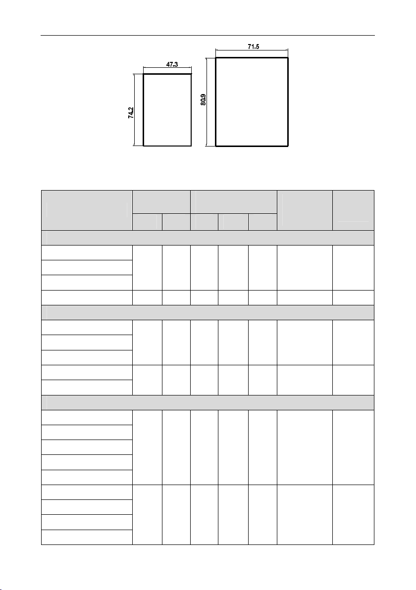
2.4 Product Appearances and Installation Dimension .................................... - 4 -
2.5 Recommended Brake Resistor Selection Table ...................................... - 7 -
2.6 Warranty Introduction............................................................ - 7 -
Chapter 3 Mechanical and Electrical Installation ........................................ - 8 -
3.1 Standard Wiring Diagram ........................................................ - 8 -
3.2 Main Circuit Terminals ........................................................... - 8 -
3.3 Control Circuit Terminal .......................................................... - 9 -
Chapter 4 Operation and Display ....................................................- 12 -
4.1 Introduction to Operation and Display Interface.....................................- 12 -
Chapter 5 Function Parameter Table ................................................. - 14 -
Chapter 6 Parameter Description .................................................... - 64 -
F0 Basic Function.................................................................- 64 -
F1 Start/Stop Control Group ........................................................ - 71 -
F2 Motor 1 Parameter ............................................................. - 77 -
F3 Motor 1 Vector Control Parameter ................................................ - 79 -
F4 Motor 1 V/F Control Parameter ................................................... - 82 -
F5 Input Terminal Group ........................................................... - 86 -
F6 Output Terminal Function Group .................................................. - 98 -
F7 Keyboard and Display Function Group ........................................... - 103 -
F8 Protection Parameters ......................................................... - 107 -
F9 Fault Record and Setting Parameter Group ....................................... - 110 -
FA Process PID Parameter Group .................................................. - 114 -
Fb Enhance Function Group ....................................................... - 118 -
Fd MODBUS Communication Parameter Group ...................................... - 132 -
FF User Parameters Group........................................................ - 133 -
FP Factory Parameter Group ...................................................... - 135 -
A0 Motor 1 Torque Control Parameter Group ......................................... - 135 -
AI Optimize Control Parameter Group ............................................... - 138 -
b0 User Customize Function Code.................................................. - 141 -
b1 Virtual IO Parameter Group ..................................................... - 142 -
b2 AI Curve Setting Parameter Group ............................................... - 146 -
b3 AIAO Correction Parameter Group ............................................... - 148 -
U0 Basic Monitoring Parameters Group ............................................. - 149 -
Chapter 7 EMC Guide ............................................................ - 151 -
7.1 Definition .................................................................... - 151 -
7.2 EMC Standard Introduction..................................................... - 151 -
7.3 EMC Guide .................................................................. - 151 -
Chapter 8 Fault Shooting and Solutions ............................................. - 153 -
8.1 Fault Alarm and Countermeasures .............................................. - 153 -
8.2 Common Faults and Solutions .................................................. - 157 -

Chapter 9 Communication Protocol ................................................. - 158 -
9.1 About Protocol ............................................................... - 158 -
9.2 Application Methods........................................................... - 158 -
9.3 Bus Structure ................................................................ - 158 -
9.4 Protocol Description........................................................... - 158 -
9.5 Communication Frame Structure ................................................ - 158 -
9.6 Command Code and Communication Data Description ............................. - 159 -
Fd MODBUS Communication ...................................................... - 167 -

VD120 Series Inverter User Manual
Safety and Precautions
- 1 -
Chapter 1 Safety and Precautions
1.1 Safety Precautions
1.1.1 At Wiring
● Wiring must be performed only by qualified personnel under instructions described in this
manual. Failure to comply may result in unexpected accidents.
● A circuit breaker must be used to isolate the power supply and inverter. Failure to comply may
result in a fire.
● Ensure that the power supply is cut off before wiring. Failure to comply may result in electric
shock.
● Connect inverter to ground properly by standard. Failure to comply may result in electric shock.
● Do not connect the input power with output terminals U, V, W, confirm the mark on terminal
before connection to avoid wrong wiring. Failure to comply can damage the inverter!
● Never connect the braking resistor between the DC bus terminals P+ and P-. Failure to comply
may result in a fire.
● The wire size of main circuit should conformed to standard, the wiring should comply with EMC
and local safety standard. Failure to comply may result in accidents.
● Use shielded cable for input output control circuit of analog and rapid speed pulse signal, and
ensure the shielding layer is reliably grounded.
1.1.2 Before Power-on:
● Check that the following requirements are met:
● The voltage class of the power supply is consistent with the rated voltage class of the AC drive.
● The input terminals (R, S, T) and output terminals (U, V, W) are properly connected.
● No short-circuit exists in the peripheral circuit.
● The wiring is secured.
● The external units of inverter and wires are configured under the manual instructed, all matched
circuit and wiring are correctly connected.
● Failure to comply will result in damage to inverter!
1.1.3 After Power-on
● Do not open the cover after inverter power-on to prevent electric shock.
● Do not touch or operate the inverter with wet hands. Failure to comply will result in electric shock.
● Do not touch any terminal of inverter after power-on, or drag connection cable. Failure to comply
will result in equipment damage or electric shock.
● Do not try to check or change the manufacturer parameter. Failure to comply may result in
malfunction or damage to inverter!
● Make sure the mechanical equipment is ready to start before inverter run with loading, make sure
related staff is in safety zone. Failure to comply will result in damage or personal hurt!
● Please pay attention to hiding accident which may result in personal hurt or property damage
while motor is run, if it is necessary to identify the motor parameter.
This manual suits for next models
18
Table of contents
Other Vicruns Inverter manuals
Popular Inverter manuals by other brands

BARRON
BARRON EXITRONIX Tucson Micro Series installation instructions

Baumer
Baumer HUBNER TDP 0,2 Series Mounting and operating instructions

electroil
electroil ITTPD11W-RS-BC Operation and Maintenance Handbook

Silicon Solar
Silicon Solar TPS555-1230 instruction manual

Mission Critical
Mission Critical Xantrex Freedom SW-RVC owner's guide

HP
HP 3312A Operating and service manual