Victaulic VicFlex AH1 User manual

I-VICFLEX.AB1/AB2/AB10INSTALLATION INSTRUCTIONS
Victaulic®VicFlex™Flexible Hose with Fittings for Fire Protection Service
Styles AB1, AB2, and AB10 Brackets
I-VICFLEX.AB1/AB2/AB10_1
REV_R
WARNING
• Read and understand all instructions before attempting to install any Victaulic products.
• Always verify that the piping system has been completely depressurized and drained immediately prior
to installation, removal, adjustment, or maintenance of any Victaulic products.
• Confirm that any equipment, branch lines, or sections of piping that may have been isolated for/
during testing or due to valve closures/positioning are identified, depressurized, and drained
immediately prior to installation, removal, adjustment, or maintenance of any Victaulic products.
• Wear safety glasses, hardhat, and foot protection.
Failure to follow these instructions could result in death or serious personal injury and property damage.
• This Victaulic®VicFlex™product shall be used only in fire protection systems that are designed and installed in accordance with current,
applicable National Fire Protection Association (NFPA 13, 13D, 13R, etc.) standards, or equivalent standards, and in accordance with
applicable building and fire codes. These standards and codes contain important information regarding protection of systems from freezing
temperatures, corrosion, mechanical damage, etc.
• These installation instructions are intended for an experienced, trained installer. The installer shall understand the use of this product and
why it was specified for the particular application.
• The installer shall understand common industry safety standards and potential consequences of improper product installation.
• It is the system designer’s responsibility to verify suitability of stainless steel flexible hose for use with the intended fluid media within the
piping system and external environment.
• The material specifier shall evaluate the effect of chemical composition, pH level, operating temperature, chloride level, oxygen level, and
flow rate on stainless steel components to confirm system life will be acceptable for the intended service.
Failure to follow installation requirements and local and national codes and standards could compromise system integrity or cause system
failure, resulting in death or serious personal injury and property damage.
Flexible Hose Listing and Approval Information
Flexible Hose
G412024
104l
AH1 With AB1, AB2, AB10 With AB1, AB2, AB10 With AB1, AB2, AB10 With AB1, AB2, AB10 With AB1, AB2, AB10
AH1-CC With AB1, AB2, AB10 With AB1, AB2, AB10 With AB1, AB2, AB10 With AB1, AB2, AB10 –
AH2 With AB1, AB2, AB10 With AB1, AB2, AB10 With AB1, AB2, AB10 With AB1, AB2, AB10 With AB1, AB2, AB10
AH2-CC With AB1, AB2, AB10 With AB1, AB2, AB10 With AB1, AB2, AB10 With AB1, AB2, AB10 –
AH2-300 With AB2 With AB1, AB2, AB10 – – –
AH2-CC-300 With AB2 With AB1, AB2, AB10 – – –
AH2-638 –With AB1, AB2, AB10 – – –
AH3* –With AB2 With AB2 –With AB1, AB2, AB10
AH4* –With AB1, AB2, AB10 With AB1, AB2, AB10 –With AB1, AB2, AB10
* SERIES AH3 AND AH4 – REGIONAL AVAILABILITY ONLY
NOTE: Flexible hoses are available in lengths from 31 - 72 inches/787 - 1829 mm with either ½-inch/DN15 or ¾-inch/DN20 NPT or BSPT threaded
outlets.

I-VICFLEX.AB1/AB2/AB10_2 REV_R
I-VICFLEX.AB1/AB2/AB10 / Victaulic®VicFlex™Styles AB1/AB2/AB10 Brackets / Installation Instructions
IMPORTANT INSTALLATION INFORMATION
• Victaulic®VicFlex™products shall be installed according to
current, applicable National Fire Protection Association (NFPA
13, 13D, 13R, etc.) standards or equivalent standards and in
accordance with applicable building and fire codes. Victaulic®
VicFlex™products are intended to be installed in wet, dry, or
preaction actuated systems. Deviations from these standards or
alterations to Victaulic®VicFlex™products or sprinklers will void
any Victaulic warranty and will impact system integrity. Installations
shall meet the provisions of the local authority having jurisdiction
and local codes, as applicable, and shall comply with all design
specifications.
• Drop ceiling construction shall meet the requirements of ASTM
C635 and shall be installed in accordance with ASTM C636.
• Victaulic® VicFlex™Sprinkler Fittings and Style AB1, AB2, or AB10
Brackets shall not be intermixed with other manufacturer’s flexible
sprinkler products.
• When using recessed sprinklers, the standard long elbow reducer
is recommended.
• Refer to the specific Victaulic product publication for
applications and listing information. In addition, when installing
Victaulic FireLock®Automatic Sprinklers with Victaulic®
VicFlex™Sprinkler Fittings, refer to the I-40 Installation and
Maintenance Instructions for details on sprinkler installation
requirements. Product publications and installation instructions
can be downloaded at victaulic.com.
• Size the piping system to meet or exceed the minimum required
flow rate for the sprinkler system.
• Per NFPA requirements, flush the system to remove foreign
material. Continue to flush the system until water runs clear.
• DO NOT install sprinkler system piping through heating ducts.
• DO NOT connect sprinkler system piping to domestic hot water
systems.
• DO NOT allow electrical wiring or other cabling to be hung or
wrapped around the sprinkler piping system.
• DO NOT install sprinklers and sprinkler fittings where ambient
conditions may fall below or exceed the maximum listed or
approved temperature ratings.
• The flexible hose shall not be bent or fluctuated up-and-down or
side-to-side when pressurized.
• Victaulic VicFlex flexible hoses may be painted or coated, provided
that the paint or coating is compatible with stainless steel material.
Care shall be taken to ensure that the sprinkler and associated
components are not painted.
• Flexible hose and fittings have limited flexibility* and are
intended only to be installed with bends not less than their
respective minimum bend radii. DO NOT install flexible hose in
a straight configuration.
• Protect wet piping systems from freezing temperatures.
• If construction is altered, the building owner or their representative
is responsible for referencing applicable standards to determine if
additional sprinklers or other system adjustments are required.
• The building owner or their representative is responsible for
maintaining the fire protection system in proper operating
condition.
• After installation is complete, the entire sprinkler system shall be
tested in accordance with applicable standards (NFPA 13, NFPA
25, etc.) that describe the care and maintenance of sprinkler
systems. In addition, the authority having jurisdiction may have
additional maintenance, testing, and inspection requirements that
shall be followed. NOTE: A successful test is not a substitute for
proper system installation and maintenance.
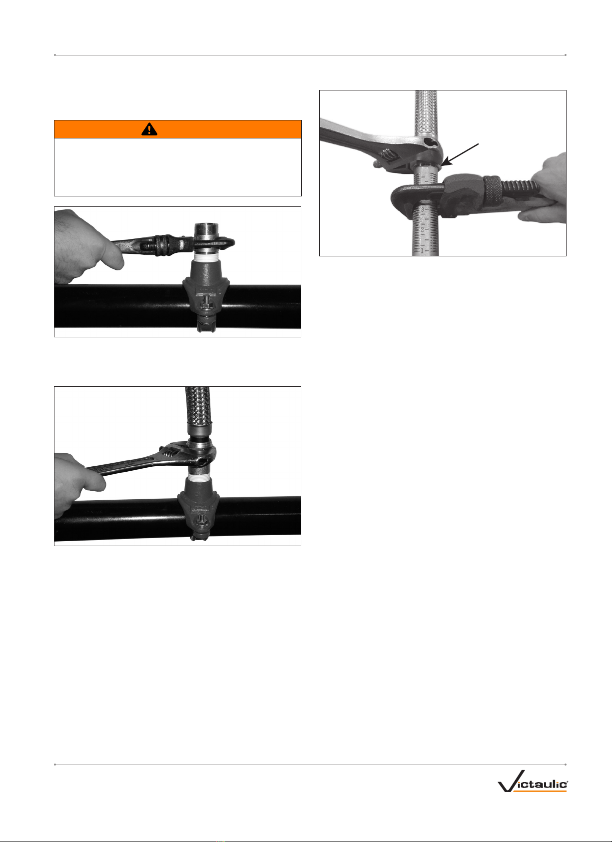
WARNING
• Relocation of Victaulic®VicFlex™ products SHALL be performed
by qualified personnel familiar with the system’s original design
criteria, sprinkler listings/approvals, and state and local codes
(including NFPA 13 standards).
Failure to relocate this Victaulic® VicFlex™product properly could
affect its performance during a fire, resulting in death or serious
personal injury and property damage.
* Reference UL 2443: Section 25.1
INTRODUCTION
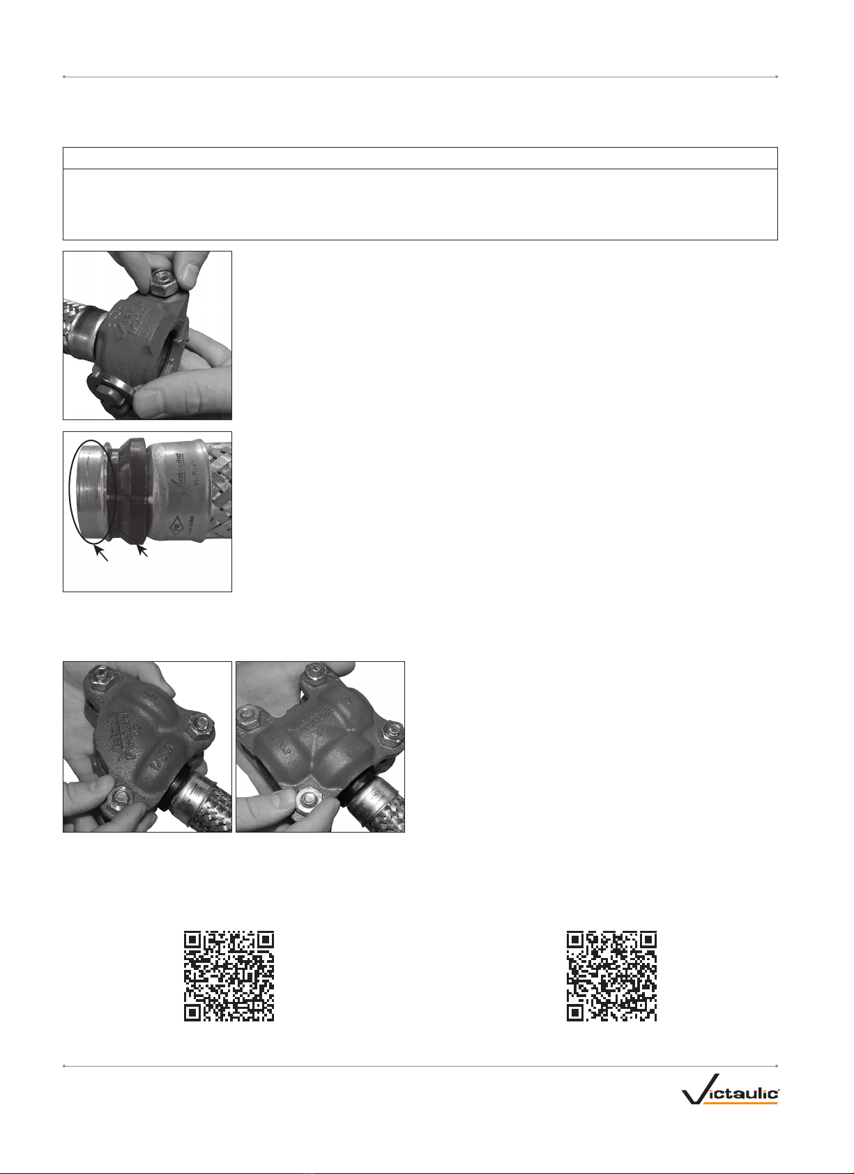
Victaulic®VicFlex™Sprinkler Fittings connect the sprinkler piping directly to the sprinkler using a flexible hose and fittings and are designed for use
in ceiling suspension systems. Each drop assembly comes with one flexible hose, one adapter nipple or captured coupling, one sprinkler reducing
nipple, and the Style AB1, AB2, or AB10 Bracket.
Maximum Working Pressure Rating of Flexible Hose:
200 psi/14 Bar/1379 kPa (FM)
175 psi/12 Bar/1207 kPa (UL)
16 Bar/1600 kPa/232 psi (VdS and LPCB)
1.4 MPa/1400 kPa/203 psi (CCC)
300 psi/21 Bar/2068 kPa (FM – Series AH2-300, AH2-CC-300)
300 psi/21 Bar/2068 kPa (UL – Series AH2-300, AH2-CC-300)
Maximum Ambient Temperature Rating of Flexible Hose:
225° F/107° C (UL, FM, VdS, LPCB)
135° C/275° F (CCC – Series AH3, AH4)
150° F/66° C (UL – Series AH2-CC-300)
Connection to Sprinkler Piping:
1 inch/DN25 NPT/BSPT (UL, FM, CCC)
1 inch/DN25 IGS (UL, FM, VdS)
DN20/¾ inch BSPT (VdS)
DN32/1 ¼ inch BSPT (LPCB)
Minimum Bend Radius of Flexible Hose:
3 inch/76 mm (UL – Series AH1, AH1-CC, AH2-300,
AH2-CC-300)
2 inch/50 mm (UL – Series AH2, AH2-CC)
7 inch/178 mm (FM – Series AH1, AH1-CC, AH2, AH2-CC, AH3,
AH4, AH2-638)
76 mm/3 inch (VdS – Series AH1, AH1-CC, AH2, AH2-CC, AH3,
AH4)
76 mm/3 inch (LPCB – Series AH1, AH1-CC, AH2, AH2-CC)
178 mm/7 inch (CCC – Series AH1, AH2, AH3, AH4)
8 inch/203 mm (FM – Series AH2-300, AH2-CC-300)
Maximum K-Factor of Sprinkler to be Connected to Sprinkler
Reducing Nipple:
Refer to footnotes in the “Friction Loss Data” section
Maximum Number of 90° Bends Per Flexible Hose:
Refer to the “Friction Loss Data” section
Flexible Hose Bend Characteristics:
NOTE: Care shall be taken to avoid torquing the flexible hose.
90°
OR
OR
Minimum
Bend Radius
Minimum
Bend Radius Minimum
Bend Radius
Minimum
Bend Radius
Minimum
Bend Radius
Minimum
Bend Radius
Minimum
Bend Radius
2X
Minimum
Bend
Radius
2X
Minimum
Bend
Radius
SCAN QR CODE FOR ACCESS TO THE FULL
I-VICFLEX.BRG BEND RADIUS GUIDE INSTRUCTIONS
ON VICTAULIC.COM

I-VICFLEX.AB1/AB2/AB10_3
REV_R
I-VICFLEX.AB1/AB2/AB10 / Victaulic®VicFlex™Styles AB1/AB2/AB10 Brackets / Installation Instructions
Item AB1 Description AB2 Description AB10 Description
124-inch/610-mm or 48-inch/1219-mm Square Bar* 24-inch/610-mm or 48-inch/1219-mm Square Bar* 6-inch/152-mm Square Bar*
2Center Gate Assembly with Wing Nut Center Gate Assembly with Adjustment Wing Screw Center Gate Assembly with Wing Nut
3End Bracket with Sheet Metal Screw End Bracket with Sheet Metal Screw End Bracket with Sheet Metal Screw
4Wing Screw Wing Screw Relocation Warning Label
5Relocation Warning Label Relocation Warning Label Helical Spring-Lock Washer
6Helical Spring-Lock Washer Helical Spring-Lock Washer Hex Socket Button Head Cap Screw
7Hex Socket Button Head Cap Screw Hex Socket Button Head Cap Screw –
* Reference publication 10.85 for listing information. Square bar length is in reference to nominal ceiling grid spacing.
2
3
1
5
3
7
6
4
Style AB1 Bracket
2
3
1
3
7
6
4
5
Style AB2 Bracket
2
3
6
5
1
3
6
5
4
Style AB10 Bracket
FLEXIBLE HOSE ASSEMBLY DRAWINGS - Refer to pages 14 – 19 of this manual for flexible hose technical data.
Example Series AH2 Flexible Hose
Shown Below
Example Series AH2-CC Flexible Hose
Shown Below
1
2
3
4
5
1
2
3
4
Item Example Series AH2 Description Example Series AH2-CC Description
1Flexible Hose Assembly Flexible Hose Assembly
2Adapter Nipple Coupling Assembly
3Reducer (Flexible Hose to Sprinkler) Reducer (Flexible Hose to Sprinkler)
4Shipping Cap Identification Sleeve
5Identification Sleeve –
BRACKET ASSEMBLY DRAWINGS - Refer to pages 8 – 12 of this manual for bracket installation instructions.

I-VICFLEX.AB1/AB2/AB10_4 REV_R
I-VICFLEX.AB1/AB2/AB10 / Victaulic®VicFlex™Styles AB1/AB2/AB10 Brackets / Installation Instructions
1-INCH/DN25 IGS CONNECTION TO THE
SPRINKLER PIPING USING A SERIES AH1-CC,
AH2-CC, OR AH2-CC-300 FLEXIBLE HOSE
INCORRECT - Orignal Groove System (OGS) Groove Prole
CORRECT - IGS Groove Prole
Pipe and grooves are not shown to scale
The Style 108 Coupling of the Series AH1-CC, AH2-CC, and
AH2-CC-300 shall be used ONLY with sprinkler piping connections that
are prepared to Victaulic IGS proprietary groove specifications. DO NOT
attempt to install the coupling on sprinkler piping connections that are
prepared to any other groove specification. Refer to Victaulic publication
25.14 for the IGS groove specification, which can be downloaded at
victaulic.com.
WARNING
• The flexible hose shall not be bent or fluctuated up-and-down or
side-to-side when pressurized.
Failure to follow this instruction could cause improper sprinkler
operation, resulting in death or serious personal injury and property
damage.
DO NOT REMOVE
NUT/BOLT/LINKAGE FOR
INITIAL INSTALLATION
1. DO NOT DISASSEMBLE THE COUPLING: The Style 108 Coupling
of the Series AH1-CC, AH2-CC, and AH2-CC-300 is designed so
that the installer does not need to remove the nut, bolt, or linkage
for initial installation. This facilitates installation by allowing the
installer to directly insert the sprinkler piping’s grooved end into the
coupling.
2. The outside surface of the sprinkler piping, between the groove
and the end of the sprinkler piping, shall be generally free from
indentations, projections, weld seam anomalies, and roll marks
to ensure a leak-tight seal. All oil, grease, loose paint, dirt, and
cutting particles shall be removed.
The sprinkler piping’s outside diameter (“OD”), groove dimensions,
and maximum allowable flare diameter shall be within the tolerances
published in current Victaulic IGS specifications, publication 25.14,
which can be downloaded at victaulic.com.
3. Check the gasket to verify that it is suitable for the intended
service. The color code identifies the material grade. Refer to
Victaulic publication 05.01 for the color code chart, which can
be downloaded at victaulic.com, and the “NOTICE” below for
important gasket information.
CAUTION
• If any conditions listed in the "NOTICE" below are met, a thin
coat of a compatible lubricant shall be applied only to the gasket
sealing lips to help prevent pinching, rolling, or tearing during
installation.
• DO NOT use excessive lubricant on the gasket sealing lips.
Failure to use a compatible lubricant may cause gasket damage,
resulting in joint leakage and property damage.
3a. If any conditions listed in the “NOTICE” below are met, apply a
thin coat of a compatible lubricant, such as Victaulic Lubricant
or an EPDM-compatible lubricant, only to the gasket sealing lips.
Silicone grease may be used (silicone spray is not a compatible
lubricant).
NOTICE
• Gaskets for Style 108 Coupling assemblies of Series AH1-CC,
AH2-CC, and AH2-CC-300 Flexible Hoses are pre-lubricated.
Additional lubrication is not required for the initial installation of
wet pipe systems that are installed at or continuously operating
above 0°F/–18°C.
Supplemental lubrication is required only if any of the following
conditions exist. Apply a thin coat of a compatible lubricant to
the gasket sealing lips, as noted in step 3a on this page. It is
not necessary to remove the gasket from the housings to apply
additional lubricant to the gasket sealing lips.
• If the installation or continuous operating temperature is below
0°F/–18°C
• If the gasket has been exposed to fluids prior to installation
• If the surface of the gasket has a dark black or shiny appearance
• If the gasket is being installed into a dry pipe system
• If the system will be subjected to air tests prior to being filled
with water
• If the gasket was involved in a previous installation
Lubricated gaskets will not enhance sealing capabilities on
adverse sprinkler piping conditions. Sprinkler piping condition
and preparation shall conform to the requirements listed in these
product installation instructions.
WARNING
• Never leave a Style 108 Coupling of a Series AH1-CC,
AH2-CC, or AH2-CC-300 partially assembled on grooved
sprinkler piping. ALWAYS TIGHTEN THE HARDWARE
IMMEDIATELY IN ACCORDANCE WITH THESE INSTRUCTIONS.
A partially assembled coupling poses a drop or fall hazard during
installation and a burst hazard during testing.
• Keep hands away from the grooved sprinkler piping and the
openings of the coupling when attempting to insert the grooved
sprinkler piping into the coupling.
• Keep hands away from coupling openings during tightening.
Failure to follow these instructions could result in death or serious
personal injury and property damage.

I-VICFLEX.AB1/AB2/AB10_5
REV_R
I-VICFLEX.AB1/AB2/AB10 / Victaulic®VicFlex™Styles AB1/AB2/AB10 Brackets / Installation Instructions
4. Assemble the joint by
inserting the grooved end of
the sprinkler piping into the
opening of the coupling. The
grooved sprinkler piping shall
be inserted into the coupling
until contact with the center
leg of the gasket occurs. A
visual check is required to
verify that the coupling keys
align with the groove in the
sprinkler piping and engage
with the spacer on the inlet
end of the flexible hose.
WARNING
• The nut shall be tightened until metal-to-metal contact occurs at
the bolt pads, as indicated in steps 5 and 6.
• DO NOT overtighten coupling hardware.
Failure to follow instructions for tightening hardware could result in:
• Personal injury or death
• Bolt damage or fracture
• Damaged or broken bolt pads or coupling fractures
• Joint leakage and property damage
• A negative impact on system integrity
GOOD
OVAL NECK OF BOLT
SEATED PROPERLY
BAD
OVAL NECK OF BOLT
NOT SEATED PROPERLY
5. Using an impact tool or a standard socket wrench with an
⁄-inch (for Imperial nut)/17-mm (for Metric nut) deep well
socket, tighten the nut until metal-to-metal contact occurs at the
bolt pads. Verify that the oval neck of the bolt seats properly in the
bolt hole. DO NOT continue to tighten the nut after metal-to-metal
bolt pad contact is achieved. If you suspect that any hardware
has been over-tightened (as indicated by a bend in the bolt,
bulging of the nut at the bolt pad interface, or damage to the
bolt pad, etc.), the entire coupling assembly shall be replaced
immediately. NOTE: During tightening, support the hose near the
Style 108 Coupling to verify that the inlet end of the Series
AH1-CC, AH2-CC, or AH2-CC-300 Flexible Hose remains straight
and aligned with the coupling.
WARNING
• Visual inspection of each joint is required.
• Improperly assembled joints shall be corrected before the
system is tested or placed into service.
• Any components that exhibit physical damage due to improper
assembly shall be replaced before the system is tested or placed
into service.
Failure to follow these instructions could cause joint failure,
resulting in death or serious personal injury and property damage.
GOOD
BAD
6. Visually inspect the bolt pads at each joint to verify that metal-
to-metal contact is achieved, in accordance with step 5.
NOTICE
• Refer to the instructions on page 13 for reassembly
requirements.

I-VICFLEX.AB1/AB2/AB10_6 REV_R
I-VICFLEX.AB1/AB2/AB10 / Victaulic®VicFlex™Styles AB1/AB2/AB10 Brackets / Installation Instructions
INSTRUCTIONS FOR INITIAL USE OF A VICTAULIC®FIRELOCK™NO. 101 90°ELBOW OR
NO. 102 STRAIGHT TEE INSTALLATION-READY™FITTING WITH A SERIES AH1-CC, AH2-CC, OR
AH2-CC-300 FLEXIBLE HOSE (1-INCH/DN25 IGS CONNECTION)
NOTICE
• The following procedure applies only to 1-inch/DN25 No. 101 90° Elbows and No. 102 Straight Tees (IGS connection).
• No. 101 90° Elbows and No. 102 Straight Tees do not ship preassembled to the Series AH1-CC, AH2-CC, or AH2-CC-300 Flexible Hose.
• The No. 101 or No. 102 does not need to be fully disassembled for initial installation onto the inlet end of the Series AH1-CC, AH2-CC, or
AH2-CC-300 Flexible Hose.
1. Loosen the nut of the Style 108 Coupling. Remove the Style 108 Coupling from the end of the Series
AH1-CC, AH2-CC, or AH2-CC-300 Flexible Hose.
Spacer
Inspect
Inlet End
of Flexible Hose
2. Inspect the inlet end of the Series AH1-CC, AH2-CC, or AH2-CC-300 Flexible Hose to verify that there is no
damage (dents, crushed edges, etc.). A new, Victaulic-supplied Series AH1-CC, AH2-CC, or AH2-CC-300
Flexible Hose shall be used if any damage is present.
3. Verify that the spacer is oriented on the inlet end of the Series AH1-CC, AH2-CC, or AH2-CC-300 Flexible
Hose, as shown to the left.
4. Loosen and remove the hardware from the side of the No. 101 90° Elbow or No. 102 Straight Tee that is intended to connect with the inlet of the
Series AH1-CC, AH2-CC, or AH2-CC-300 Flexible Hose.
NO. 101 NO. 102 5. Insert the inlet end of the Series AH1-CC, AH2-CC, or AH2-CC-300
Flexible Hose into the No. 101 90° Elbow or No. 102 Straight Tee.
Verify that the gasket is seated fully in the gasket pocket of each
housing and that the housings' keys engage with the spacer on the
inlet end of the Series AH1-CC, AH2-CC, or AH2-CC-300 Flexible
Hose.
5a. Reinstall the two bolts and nuts that were removed in step 4.
NOTE: Verify that the oval neck of each bolt seats properly in the bolt
holes. DO NOT tighten the nuts completely. The bolt pads need to
be set at a gap for installation of the fitting. The nuts should be flush
with the top of each bolt to provide the proper gap. Use caution when
handling the fitting/hose assembly (the fitting may not be secured
completely to the inlet end of the Series AH1-CC, AH2-CC, or
AH2-CC-300 Flexible Hose).
6. Follow the steps in the I-101/103 or I-102/104 installation instructions for the required tightening sequence. NOTE: During tightening, verify
that the inlet end of the Series AH1-CC, AH2-CC, or AH2-CC-300 Flexible Hose remains straight and aligned with the opening of the No. 101
90° Elbow or No. 102 Straight Tee. The I-101/103 or I-102/104 can be accessed and downloaded by scanning the applicable QR code below. In
addition, these instructions contain important reassembly instructions and shall be referenced any time a No. 101 90° Elbow or No. 102 Straight
Tee is removed from the sprinkler piping and reused.
SCAN QR CODE FOR ACCESS TO THE FULL I-101/103
INSTALLATION INSTRUCTIONS ON VICTAULIC.COM
SCAN QR CODE FOR ACCESS TO THE FULL I-102/104
INSTALLATION INSTRUCTIONS ON VICTAULIC.COM

I-VICFLEX.AB1/AB2/AB10_7
REV_R
I-VICFLEX.AB1/AB2/AB10 / Victaulic®VicFlex™Styles AB1/AB2/AB10 Brackets / Installation Instructions
CONNECTION TO THE SPRINKLER PIPING
USING AN ADAPTER NIPPLE AND A SERIES
AH1, AH2, AH3, AH4, AH2-300, OR AH2-638
FLEXIBLE HOSE
WARNING
• The flexible hose shall not be bent or fluctuated up-and-down or
side-to-side when pressurized.
Failure to follow this instruction could cause improper sprinkler
operation, resulting in death or serious personal injury and property
damage.
1. Apply pipe joint compound or PTFE thread sealant tape to the
tapered threads of the adapter nipple, in accordance with the pipe
joint compound or tape manufacturer’s instructions. Using a pipe
wrench, tighten the adapter nipple into the sprinkler piping.
2. Confirm that the seal inside the nut of the flexible hose is in place
and is free from damage prior to installation. Connect the nut to
the adapter nipple, as shown above.
• DO NOT use pipe joint compound or PTFE thread sealant tape on
the threads of the adapter nipple. The seal inside the nut of the
flexible hose provides the leak-proof connection.
• Tighten the connection nut to a torque of 40ft-lbs/54 N•m
(approximately ½ to ¾ of a turn past hand-tight). NOTE: To prevent
damage to the seal, tighten the assembly by applying torque only
to the connection nut and DO NOT exceed the specified torque.
INSTALLATION OF THE SPRINKLER REDUCING
NIPPLE ONTO THE FLEXIBLE HOSE
TURN
CONNECTION
NUT ONLY
1. Confirm that the seal inside the nut of the flexible hose is in place
and is free from damage prior to installation. Connect the nut to
the sprinkler reducing nipple. SHORT 90° ELBOW REDUCERS
ARE TYPICALLY USED WITH CONCEALED SPRINKLERS.
• DO NOT use pipe joint compound or PTFE thread sealant tape on
the fine threads of the sprinkler reducing nipple. The seal inside
the nut of the flexible hose provides the leak-proof connection.
• Tighten the connection nut to a torque of 40ft-lbs/54 N•m
(approximately ½ to ¾ of a turn past hand-tight). NOTE: To prevent
damage to the seal, tighten the assembly by applying torque only
to the connection nut and DO NOT exceed the specified torque.

I-VICFLEX.AB1/AB2/AB10_8 REV_R
I-VICFLEX.AB1/AB2/AB10 / Victaulic®VicFlex™Styles AB1/AB2/AB10 Brackets / Installation Instructions
INSTALLATION OF STYLE AB1, AB2, AND
AB10 BRACKETS FOR ASTM C635 CEILING
SUSPENSION SYSTEMS INSTALLED IN
ACCORDANCE WITH ASTM C636 STANDARDS
FOR STYLES AB1 AND AB2 BRACKETS ONLY: For adjustment
purposes, the wing screw on top of the end bracket assembly can be
loosened to allow the end bracket to slide on the square bar. Tighten
the wing screw on top of the end bracket assembly to a torque of
36 inch-lbs/4 N•m (approximately ½ to ¾ of a turn past hand-tight) to
secure the end bracket to the square bar.
1. Attach the end brackets of the Style AB1, AB2, or AB10 Bracket
to the T-bar rails of an ASTM C635 ceiling suspension system
installed in accordance with ASTM C636 standards. Verify that the
ends of the Style AB1, AB2, or AB10 Bracket engage the rails.
Side Facing the
Opening of the
Center Gate
Assembly
1a. For center-of-tile installations, align the end bracket with the
center-of-tile slot of the T-bar rail (with the side facing the opening
of the center gate assembly), as shown above.
1b. Apply light downward pressure, as shown above, to maintain the
position of the end bracket flat against the T-bar rail. To secure
the end brackets to the T-bar rails, tighten the pre-installed sheet
metal screws using a T25 drive bit. Penetrate through the T-bar
rail until the end bracket is seated fully against the T-bar rail, as
shown above. DO NOT over-tighten the screws. Over-tightening
will cause the screw to strip, resulting in an unsecured bracket
connection.
FOR STYLES AB1 AND AB2 BRACKETS ONLY: Verify that the wing
screw on top of the end bracket assembly is tightened to a torque of
36 inch-lbs/4 N•m (approximately ½ to ¾ of a turn past hand-tight).

I-VICFLEX.AB1/AB2/AB10_9
REV_R
I-VICFLEX.AB1/AB2/AB10 / Victaulic®VicFlex™Styles AB1/AB2/AB10 Brackets / Installation Instructions
2. FOR STYLES AB1 AND AB10 BRACKETS ONLY: Move the
center gate assembly of the Style AB1/AB10 Bracket to the desired
location. Loosen the wing nut to open the center gate assembly,
then slide the sprinkler reducing nipple into the center gate
assembly. NOTE: The pivot screw of the center gate assembly is
staked to resist removal of the wing nut.
Adjustment
Wing Screw
Adjustment
Wing Screw
2a. FOR STYLE AB2 BRACKETS ONLY: Move the center gate
assembly of the Style AB2 Bracket to the desired location. Using
a T25 drive bit, loosen the adjustment wing screw, then push
open the center gate assembly. The center gate assembly may
be rotated on the square bar for ease of installation. For vertical
adjustment, rotate the center gate assembly on the square bar
so that the adjustment wing screw is facing downward. Slide the
sprinkler reducing nipple into the center gate assembly.
NOTE: The adjustment wing screw of the center gate assembly is
staked to resist removal.
For center-of tile installations, position the center gate assembly
between the two reference marks on the square bar, as shown above.
2b. FOR STYLES AB1 AND AB10 BRACKETS ONLY: Close the
center gate assembly around the sprinkler reducing nipple. Swing
the pivot screw and washer into the slot on the gate, and tighten
the wing nut to a torque of 50 inch-lbs/6 N•m (approximately
hand-tight, plus ½ to ¾ of a turn). NOTE: Verify that the washer is
seated under the head of the wing nut.
2c. FOR STYLE AB2 BRACKETS ONLY: Close the gate around the
sprinkler reducing nipple. The gate will snap together tightly
around the sprinkler reducing nipple. Using a T25 drive bit, tighten
the adjustment wing screw to a torque of 75 inch-lbs/8.5 N•m
(until adjustment wing screw makes metal-to-metal contact with
bottom of gate). NOTE: The sprinkler reducing nipple can be
adjusted after the drywall is installed by using the adjustment wing
screw on the center gate assembly (adjustment wing screw must
be facing downward to make this vertical adjustment).
SPRINKLER INSTALLATION:
Install the sprinkler by following the manufacturer’s installation
instructions. For Victaulic sprinklers, refer to the I-40 Victaulic®
FireLock™Automatic Sprinklers Installation and Maintenance
Instructions.
CEILING TILE INSTALLATION:
VicFlex Style AB1 and Style AB2 Brackets allow for the installation of
most ceiling tiles after the bracket and VicFlex flexible hose have been
installed. The following will aid in ceiling tile installation:
• Install bracket on main tee ceiling grid (or ceiling t-bar height that
is greater than 1 ⁄ inches/35 mm)
• Cut largest recommended hole, as stated in the sprinkler
manufacturer’s installation instructions
• Install sprinkler at its maximum extension
Ceiling tile installation shall be evaluated when utilizing concealed
sprinklers in combination with ceiling tile thicknesses equal to or greater
than ¾ inches/19 mm OR a ceiling t-bar height that is equal to or less
than 1 ⁄ inches/35 mm.

I-VICFLEX.AB1/AB2/AB10_10 REV_R
I-VICFLEX.AB1/AB2/AB10 / Victaulic®VicFlex™Styles AB1/AB2/AB10 Brackets / Installation Instructions
INSTALLATION OF THE STYLE AB2 BRACKET
FOR ASTM C645 HAT FURRING CHANNEL
CEILING SYSTEMS INSTALLED IN ACCORDANCE
WITH ASTM C754 STANDARDS
(FM AND VdS ONLY)
1. Using a T25 drive bit, remove the pre-installed sheet metal screw
from each Style AB2 end bracket.
NOTE: For adjustment purposes, the wing screw on top of the Style
AB2 end bracket assembly can be loosened to allow the end bracket
to slide on the square bar. Tighten the wing screw on top of the end
bracket assembly to a torque of 36 inch-lbs/4 N•m (approximately ½ to
¾ of a turn past hand-tight) to secure the end bracket to the square bar.
2. Attach the end brackets of the Style AB2 Bracket to the T-bar rails
of the CD Profile (60 mm) Channel Ceiling System. Verify that the
ends of the Style AB2 Bracket engage the rails.
3. To secure the end brackets to the T-bar rails of the CD Profile
(60 mm) Channel Ceiling System, tighten a #10 diameter x 1-inch
length sheet metal screw (not provided) into the center and bottom
right hole locations of each end bracket (four total locations), as
shown above. Penetrate each sheet metal screw through the T-bar
rail until the end bracket is seated fully against the T-bar rail.
DO NOT over-tighten the screws. Over-tightening will cause the
screws to strip, resulting in an unsecured bracket connection.
4. Verify that the wing screw on top of the end bracket assembly is
tightened to a torque of 36 inch-lbs/4 N•m (approximately ½ to ¾
of a turn past hand-tight).
5. Follow steps 2a and 2c on page 9 to complete the assembly.

I-VICFLEX.AB1/AB2/AB10_11
REV_R
I-VICFLEX.AB1/AB2/AB10 / Victaulic®VicFlex™Styles AB1/AB2/AB10 Brackets / Installation Instructions
INSTALLATION FOR WOOD JOISTS/STUDS
(FM ONLY FOR AB1 AND FM/UL FOR AB2)
1. Install the flexible hose into the sprinkler piping and the sprinkler
reducing nipple onto the flexible hose by following the applicable
instructions on pages 4 − 7.
2. Loosen the wing screw of the Style AB1 or AB2 end bracket
assembly.
1½-inch/38-mm Long #10
Wood Screws (4 Total)
Wing
Screw
3. Place the end bracket assembly (without the wing screw) against
the inside surface of the one wood joist/stud with the square bar
resting on top of the wood joist/stud, as shown in the graphic
above.
3a. Slide the end bracket assembly (with the wing screw) toward the
inside surface of the opposite wood joist/stud, as shown in the
graphic above.
4. Install the modified Style AB1 or AB2 Bracket to the wood joists/
studs by using four, 1 ½-inch/38-mm long #10 wood screws in the
locations noted in the graphic shown above. NOTE: Install the top
two wood screws first.
5. Optional: Tighten the wing screw on top of the end bracket
assembly to a torque of 36 inch-lbs/4 N•m (approximately ½ to ¾
of a turn past hand-tight).
6. Perform steps 2 − 2c on pages 8 − 9 to complete the installation.
NOTES:
• For wood joists/studs larger than 2 x 4, longer sprinkler reducing
nipples shall be used, or one of the alternative installation methods
on the following pages shall be followed.
• For the 24-inch/610-mm length Style AB2 Bracket, the maximum
on-center spacing between wood joists/studs is 20 inches/
508 mm.
INSTALLATION FOR ASTM C645 METAL JOISTS/
STUDS INSTALLED IN ACCORDANCE WITH
ASTM C754 STANDARDS
(FM ONLY FOR AB1 AND FM/UL FOR AB2)
1. Install the flexible hose into the sprinkler piping and the sprinkler
reducing nipple onto the flexible hose by following the applicable
instructions on pages 4 − 7.
2. Loosen and remove the wing screw of the Style AB1 or AB2 end
bracket assembly.
Wing Screw
1¼-inch/32-mm Long #10 Self-Drilling
Sheet Metal Screws (4 Total)
NOTE: End Bracket with
Wing Screw is Turned 180°
3. Rotate the end bracket assembly (side with the wing screw
removed in step 2) 180°, as shown in the graphic above. Reinstall
the wing screw loosely into the top of the end bracket assembly.
3a. Place the end bracket assembly (without the wing screw) against
the outside surface of the metal joist/stud with the square bar
resting on top of the metal joists/studs.
3b. Slide the end bracket assembly (with the wing screw) toward the
outside, flat surface of the opposite metal joist/stud, as shown in
the graphic above.
4. Install the modified Style AB1 or AB2 Bracket to the metal joists/
studs by using four, 1 ¼-inch/32-mm long #10 self-drilling sheet
metal screws in the locations noted in the graphic shown above.
NOTE: Install the top two sheet metal screws first.
5. Optional: Tighten the wing screw on top of the end bracket
assembly to a torque of 36 inch-lbs/4 N•m (approximately ½ to ¾
of a turn past hand-tight).
6. Perform steps 2 − 2c on pages 8 − 9 to complete the installation.
NOTES:
• For metal joists/studs larger than 2 x 4, longer sprinkler reducing
nipples shall be used, or one of the alternative installation methods
on the following pages shall be followed.
• For the 24-inch/610-mm length Style AB2 Bracket, the maximum
on-center spacing between metal joists/studs is 20 inches/
508 mm.

I-VICFLEX.AB1/AB2/AB10_12 REV_R
I-VICFLEX.AB1/AB2/AB10 / Victaulic®VicFlex™Styles AB1/AB2/AB10 Brackets / Installation Instructions
ALTERNATIVE #1 – WOOD JOIST/STUD
INSTALLATION (FM ONLY FOR AB1 AND AB2)
1. Install the flexible hose into the sprinkler piping and the sprinkler
reducing nipple onto the flexible hose by following the applicable
instructions on pages 4 − 7.
2. Loosen and remove the wing screw of the Style AB1 or AB2 end
bracket assembly. Remove the end bracket assembly from the
square bar.
3. Measure the distance between the wood joists/studs.
3a. Cut the square bar to the length needed to fit between the two
wood joists/studs. This length shall be measured from the outside
of the end bracket assembly to the point on the square bar that
will butt against the other wood joist/stud.
1½-inch/38-mm Long #10
Wood Screws (4 Total)
Wing
Screw
4. Place the end bracket assembly, removed in step 2, onto the end
of the square bar so that the square bar is flush with the outside of
the end bracket assembly. Reinstall the wing screw loosely into the
top of the end bracket assembly.
5. Install the modified Style AB1 or AB2 Bracket between the wood
joists/studs by using four, 1 ½-inch/38-mm long #10 wood screws
in the locations noted in the graphic shown above. NOTE: Install
the top two wood screws first.
6. Tighten the wing screw on top of the end bracket assembly to a
torque of 36 inch-lbs/4 N•m (approximately ½ to ¾ of a turn past
hand-tight).
7. Perform steps 2 − 2c on pages 8 − 9 to complete the installation.
ALTERNATIVE #1 – METAL JOIST/STUD
INSTALLATION (FM ONLY FOR AB1 AND AB2)
1. Install the flexible hose into the sprinkler piping and the sprinkler
reducing nipple onto the flexible hose by following the applicable
instructions on pages 4 − 7.
2. Loosen and remove the wing screw of the Style AB1 or AB2 end
bracket assembly. Remove the end bracket assembly from the
square bar.
3. Measure the distance between the metal joists/studs.
3a. Cut the square bar to the length needed to fit between the two
metal joists/studs. This length shall be measured from the outside
of the end bracket assembly to the point on the square bar that
will butt against the other metal joist/stud.
Wing
Screw
1¼-inch/32-mm Long #10 Self-Drilling
Sheet Metal Screws (4 Total)
4. Place the end bracket assembly, removed in step 2, onto the end
of the square bar so that the square bar is flush with the outside of
the end bracket assembly. Reinstall the wing screw loosely into the
top of the end bracket assembly.
5. Install the modified Style AB1 or AB2 Bracket between the metal
joists/studs by using four, 1 ¼-inch/32-mm long #10 self-drilling
sheet metal screws in the locations noted in the graphic shown
above. NOTE: Install the top two sheet metal screws first.
6. Tighten the wing screw on top of the end bracket assembly to a
torque of 36 inch-lbs/4 N•m (approximately ½ to ¾ of a turn past
hand-tight).
7. Perform steps 2 − 2c on pages 8 − 9 to complete the installation.

I-VICFLEX.AB1/AB2/AB10_13
REV_R
I-VICFLEX.AB1/AB2/AB10 / Victaulic®VicFlex™Styles AB1/AB2/AB10 Brackets / Installation Instructions
ALTERNATIVE #2 – WOOD JOIST/STUD
INSTALLATION (FM ONLY FOR AB1 AND AB2)
1. Install the flexible hose into the sprinkler piping and the sprinkler
reducing nipple onto the flexible hose by following the applicable
instructions on pages 4 − 7.
2. Loosen and remove the wing screw of the Style AB1 or AB2 end
bracket assembly. Remove the end bracket assembly from the
square bar.
2a. FOR STYLE AB2 BRACKETS ONLY: Remove and turn the
center gate assembly 180° so that the adjustment screw is facing
downward when the bracket is installed in the orientation shown
below.
3. Measure the distance between the wood joists/studs.
3a. Cut the square bar to the length needed to fit between the two
wood joists/studs. This length shall be measured from the outside
of the end bracket assembly to the point on the square bar that
will butt against the other wood joist/stud.
1½-inch/38-mm Long
#10 Wood Screw
(4 Total)
Wing Screw Center Gate
Assembly
Turned 180º
4. Place the end bracket assembly, removed in step 2, onto the end
of the square bar so that the square bar is flush with the outside of
the end bracket assembly. Reinstall the wing screw loosely into the
top of the end bracket assembly.
5. Install the modified Style AB1 or AB2 Bracket between the wood
joists/studs by using four, 1 ½-inch/38-mm long #10 wood screws
in the locations noted in the graphic shown above. NOTE: Install
the top two wood screws first.
6. Tighten the wing screw on top of the end bracket assembly to a
torque of 36 inch-lbs/4 N•m (approximately ½ to ¾ of a turn past
hand-tight).
7. Perform steps 2 − 2c on pages 8 − 9 to complete the installation.
ALTERNATIVE #2 – METAL JOIST/STUD
INSTALLATION (FM ONLY FOR AB1 AND AB2)
1. Install the flexible hose into the sprinkler piping and the sprinkler
reducing nipple onto the flexible hose by following the applicable
instructions on pages 4 − 7.
2. Loosen and remove the wing screw of the Style AB1 or AB2 end
bracket assembly. Remove the end bracket assembly from the
square bar.
2a. FOR STYLE AB2 BRACKETS ONLY: Remove and turn the
center gate assembly 180° so that the adjustment screw is facing
downward when the bracket is installed in the orientation shown
below.
3. Measure the distance between the metal joists/studs.
3a. Cut the square bar to the length needed to fit between the two
metal joists/studs. This length shall be measured from the outside
of the end bracket assembly to the point on the square bar that
will butt against the other metal joist/stud.
1¼-inch/32-mm Long
#10 Self-Drilling
Sheet Metal Screws
(4 Total)
Wing Screw Center Gate
Assembly
Turned 180º
4. Place the end bracket assembly, removed in step 2, onto the end
of the square bar so that the square bar is flush with the outside of
the end bracket assembly. Reinstall the wing screw loosely into the
top of the end bracket assembly.
5. Install the modified Style AB1 or AB2 Bracket between the metal
joists/studs by using four, 1 ¼-inch/32-mm long #10 self-drilling
sheet metal screws in the locations noted in the graphic shown
above. NOTE: Install the top two sheet metal screws first.
6. Tighten the wing screw on top of the end bracket assembly to a
torque of 36 inch-lbs/4 N•m (approximately ½ to ¾ of a turn past
hand-tight).
7. Perform steps 2 − 2c on pages 8 − 9 to complete the installation.

I-VICFLEX.AB1/AB2/AB10_14 REV_R
I-VICFLEX.AB1/AB2/AB10 / Victaulic®VicFlex™Styles AB1/AB2/AB10 Brackets / Installation Instructions
INSTRUCTIONS FOR REASSEMBLY OF A SERIES
AH1-CC, AH2-CC, OR AH2-CC-300 FLEXIBLE
HOSE
WARNING
• Always verify that the piping system has
been completely depressurized and drained
immediately prior to installation, removal,
adjustment, or maintenance of any Victaulic
products.
• Confirm that any equipment, branch lines, or sections of piping
that may have been isolated for/during testing or due to valve
closures/positioning are identified, depressurized, and drained
immediately prior to installation, removal, adjustment, or
maintenance of any Victaulic products.
Failure to follow this instruction could result in death or serious
personal injury and property damage.
1. Verify that the system is depressurized and drained completely
before attempting to remove a Series AH1-CC, AH2-CC, or
AH2-CC-300 Flexible Hose from the sprinkler piping.
2. While supporting the Style 108 Coupling, loosen the nut until
backed off no further than flush with the end of the bolt. Carefully
remove the flexible hose/coupling assembly from the sprinkler
piping.
3. Fully disassemble the Style 108 Coupling from the inlet end of
the Series AH1-CC, AH2-CC, or AH2-CC-300 Flexible Hose by
removing the nut, bolt, gasket, and linkage from the housings.
Inspect all components for any damage or wear. If any damage or
wear is present, use a new Victaulic-supplied coupling assembly.
4. Verify that the outside surface of the sprinkler piping, between the
groove and the end of the sprinkler piping, is generally free from
indentations, projections, weld seam anomalies, and roll marks
to ensure a leak-tight seal. All oil, grease, loose paint, dirt, and
cutting particles shall be removed.
The sprinkler piping’s outside diameter (“OD”), groove
dimensions, and maximum allowable flare diameter shall
be within the tolerances published in current Victaulic IGS
specifications, publication 25.14, which can be downloaded at
victaulic.com.
Spacer
Inspect
Inlet End
of Flexible Hose
5. Inspect the end of the Series AH1-CC, AH2-CC, or AH2-CC-300
Flexible Hose to verify that there is no damage (dents, crushed
edges, etc.). A new, Victaulic-supplied Series AH1-CC, AH2-CC, or
AH2-CC-300 Flexible Hose shall be used if any damage is present.
6. Verify that the spacer is oriented on the inlet end of the Series
AH1-CC, AH2-CC, or AH2-CC-300 Flexible Hose, as shown above.
CAUTION
• A thin coat of a compatible lubricant shall be used to help
prevent the gasket from pinching, rolling, or tearing during
reassembly.
• DO NOT use excessive lubricant on the gasket sealing lips and
exterior.
Failure to use a compatible lubricant may cause gasket damage,
resulting in joint leakage and property damage.
7. Apply a thin coat of a compatible lubricant, such as Victaulic
Lubricant or an EPDM-compatible lubricant, to the gasket sealing
lips and exterior. Silicone grease may be used (silicone spray is not
a compatible lubricant). It is normal for the gasket to have a hazy
white appearance after it has been in service.
8. Place the lubricated gasket
onto the inlet end of the
flexible hose, then place the
Style 108 Coupling housings
over the gasket. Verify that
the gasket is seated fully
in the gasket pocket of
each housing and that the
housings' keys engage with
the spacer.
9. Install the linkage onto the
housings, as shown to the
left.
10. Install the bolt, and thread a
nut onto the bolt.
NOTE: Verify that the oval
neck of the bolt seats
properly in the bolt hole.
DO NOT tighten the nut
completely. The bolt pads
need to be set at a gap for
reinstallation of the coupling.
The nut should be flush with
the top of the bolt to provide
the proper gap.
11. Follow all steps on page 5.

I-VICFLEX.AB1/AB2/AB10_15
REV_R
I-VICFLEX.AB1/AB2/AB10 / Victaulic®VicFlex™Styles AB1/AB2/AB10 Brackets / Installation Instructions
TECHNICAL DATA FOR
FLEXIBLE HOSES
The following section provides friction loss
information for flexible hoses that can be used
with Style AB1, AB2, and AB10 Brackets.
WARNING
• It is the system designer’s responsibility to verify suitability of stainless steel flexible hose for
use with the intended fluid media within the piping system and external environment.
• The material specifier shall evaluate the effect of chemical composition, pH level, operating
temperature, chloride level, oxygen level, and flow rate on stainless steel components to confirm
system life will be acceptable for the intended service.
Failure to follow these instructions could cause product failure, resulting in death or serious
personal injury and property damage.

I-VICFLEX.AB1/AB2/AB10_16 REV_R
I-VICFLEX.AB1/AB2/AB10 / Victaulic®VicFlex™Styles AB1/AB2/AB10 Brackets / Installation Instructions
SERIES AH1 AND AH1-CC FLEXIBLE HOSE FRICTION LOSS DATA (FM AND UL)
Model
Length of Flexible Hose
inches/mm
Outlet Size#
inches/Metric
Equivalent Length of 1-inch/DN25 Schedule 40 Pipe
feet/meters
Maximum Number
of 90° Bends§
FM* UL‡ FM UL
AH1-31
AH1-CC-31
31
790
½53.8 52.0
2 3
DN15 16.4 15.9
¾44.3 55.0
DN20 13.5 16.8
AH1-36
AH1-CC-36
36
915
½63.7 63.0
2 4
DN15 19.4 19.2
¾55.5 66.0
DN20 16.9 20.1
AH1-48
AH1-CC-48
48
1220
½87.9 78.0
3 4
DN15 26.8 23.8
¾83.0 80.0
DN20 25.3 24.4
AH1-60
AH1-CC-60
60
1525
½112 . 2 88.0
4 4
DN15 34.1 26.8
¾110.4 90.0
DN20 33.6 27.4
AH1-72
AH1-CC-72
72
1830
½136.5 112.0
4 5
DN15 41.6 34.1
¾137.9 118 .0
DN20 42.0 36.0
* 7-inch/178-mm minimum bend radius (tested with standard 5 ¾-inch/146-mm length straight reducer)
‡ 3-inch/76-mm minimum bend radius (tested and UL Listed only with standard 5 ¾-inch/146-mm length straight reducer)
# ¾-inch/DN20 outlet data shown with K14.0 - For other K-factor friction loss data, refer to Victaulic publication 10.95
For the UL Listing, when the 48-inch/1220-mm length bracket is used with the Series AH1 or AH1-CC Flexible Hose, the maximum sprinkler K-factor is K8.0 and the
maximum spacing is 30 inches/762 mm
§ A higher number of bends may be permitted, provided the sum of degrees is equal to or less than the total maximum allowable degrees of bends
(e.g. Two 90° bends equal 180°. Three 90° bends equal 270°). The minimum bend radius and maximum number of 90° offset (bends), stated in these installation instructions,
refer to the final installed condition of the hose.
For friction loss data for elbows, refer to Victaulic publication 10.95.
NOTE: Differences in equivalent lengths are due to varying test methods, per UL 2443 and FM 1637 standards. Refer to these standards for additional information regarding
friction loss test methods.
When using a No. 101 90° Elbow or a No. 102 Straight Tee in place of a Style 108 Coupling on the end of a Series AH1-CC Flexible Hose, the friction loss data shown
above shall be added to the No. 101 or No. 102 friction loss data published in Victaulic publication 10.54.
SERIES AH2 AND AH2-CC FLEXIBLE HOSE FRICTION LOSS DATA (FM AND UL)
Model
Length of Flexible Hose
inches/mm
Outlet Size#
inches/Metric
Equivalent Length of 1-inch/DN25 Schedule 40 Pipe
feet/meters
Maximum Number
of 90° Bends§
FM* UL‡ FM UL
AH2-31
AH2-CC-31
31
790
½13.8 16.0
2 4
DN15 4.2 4.9
¾14.9 18.0
DN20 4.5 5.5
AH2-36
AH2-CC-36
36
915
½16.6 21.0
2 5
DN15 5.1 6.4
¾19.4 23.0
DN20 5.9 7. 0
AH2-48
AH2-CC-48
48
1220
½23.4 32.0
3 8
DN15 7.1 9.8
¾30.3 37.0
DN20 9.2 11. 3
AH2-60
AH2-CC-60
60
1525
½30.2 46.0
410
DN15 9.2 14.0
¾33.9 46.0
DN20 10.3 14.0
AH2-72
AH2-CC-72
72
1830
½37.0 55.0
412
DN15 11. 3 16.8
¾37. 5 60.0
DN20 11. 4 18.3
* 7-inch/178-mm minimum bend radius (tested with standard 5 ¾-inch/146-mm length straight reducer)
‡ 2-inch/50-mm minimum bend radius (tested and UL Listed only with standard 5 ¾-inch/146-mm length straight reducer)
# ¾-inch/DN20 outlet data shown with K14.0 - For other K-factor friction loss data, refer to Victaulic publication 10.85
For the UL Listing, when the 48-inch/1220-mm length bracket is used with the Series AH2 or AH2-CC Flexible Hose, the maximum sprinkler K-factor is K8.0 and the
maximum spacing is 30 inches/762 mm
§ A higher number of bends may be permitted, provided the sum of degrees is equal to or less than the total maximum allowable degrees of bends
(e.g. Two 90° bends equal 180°. Three 90° bends equal 270°). The minimum bend radius and maximum number of 90° offset (bends), stated in these installation instructions,
refer to the final installed condition of the hose.
For friction loss data for elbows, refer to Victaulic publication 10.85.
NOTE: Differences in equivalent lengths are due to varying test methods, per UL 2443 and FM 1637 standards. Refer to these standards for additional information regarding
friction loss test methods.
When using a No. 101 90° Elbow or a No. 102 Straight Tee in place of a Style 108 Coupling on the end of a Series AH2-CC Flexible Hose, the friction loss data shown
above shall be added to the No. 101 or No. 102 friction loss data published in Victaulic publication 10.54.

I-VICFLEX.AB1/AB2/AB10_17
REV_R
I-VICFLEX.AB1/AB2/AB10 / Victaulic®VicFlex™Styles AB1/AB2/AB10 Brackets / Installation Instructions
SERIES AH2-300 AND AH2-CC-300 FLEXIBLE HOSE FRICTION LOSS DATA (FM)
Model
Length of Flexible Hose
inches/mm
Outlet Size#
inches/Metric
Equivalent Length of 1-inch/DN25 Schedule 40 Pipe
feet/meters*
Maximum Number
of 90° Bends§
AH2-300-31
AH2-CC-300-31
31
790
½13.8
2
DN15 4.2
¾14.9
DN20 4.5
AH2-300-36
AH2-CC-300-36
36
915
½16.6
2
DN15 5.1
¾19.4
DN20 5.9
AH2-300-48
AH2-CC-300-48
48
1220
½23.4
3
DN15 7.1
¾30.3
DN20 9.2
AH2-300-60
AH2-CC-300-60
60
1525
½30.2
4
DN15 9.2
¾33.9
DN20 10.3
AH2-300-72
AH2-CC-300-72
72
1830
½37.0
4
DN15 11. 3
¾37. 5
DN20 11. 4
* 8-inch/203-mm minimum bend radius (tested with standard 5 ¾-inch/146-mm length straight reducer)
# ¾-inch outlet data shown with K14.0 - For other K-factor friction loss data, refer to Victaulic publication 10.84
§ A higher number of bends may be permitted, provided the sum of degrees is equal to or less than the total maximum allowable degrees of bends
(e.g. Two 90° bends equal 180°. Three 90° bends equal 270°). The minimum bend radius and maximum number of 90° offset (bends), stated in these installation instructions,
refer to the final installed condition of the hose.
For friction loss data for elbows, refer to Victaulic publication 10.84.
NOTE: Differences in equivalent lengths are due to varying test methods, per the FM 1637 standard. Refer to this standard for additional information regarding friction loss
test methods.
SERIES AH2-300 AND AH2-CC-300 FLEXIBLE HOSE FRICTION LOSS DATA (UL)
Model
Length of Flexible Hose
inches/mm
Outlet Size#
inches/Metric
Equivalent Length of 1-inch/DN25 Schedule 40 Pipe
feet/meters*
Maximum Number
of 90° Bends§
AH2-300-31
AH2-CC-300-31
31
790
½17.0
3
DN15 5.2
¾16.0
DN20 4.9
AH2-300-36
AH2-CC-300-36
36
915
½25.0
4
DN15 7.6
¾22.0
DN20 6.7
AH2-300-48
AH2-CC-300-48
48
1220
½30.0
4
DN15 9.1
¾28.0
DN20 8.5
AH2-300-60
AH2-CC-300-60
60
1525
½32.0
4
DN15 9.8
¾31.0
DN20 9.4
AH2-300-72
AH2-CC-300-72
72
1830
½40.0
5
DN15 12. 2
¾36.0
DN20 11. 0
* 8-inch/203-mm minimum bend radius (tested with standard 5 ¾-inch/146-mm length straight reducer)
# ¾-inch outlet data shown with K14.0 - For other K-factor friction loss data, refer to Victaulic publication 10.84
§ A higher number of bends may be permitted, provided the sum of degrees is equal to or less than the total maximum allowable degrees of bends
(e.g. Two 90° bends equal 180°. Three 90° bends equal 270°). The minimum bend radius and maximum number of 90° offset (bends), stated in these installation instructions,
refer to the final installed condition of the hose.
For friction loss data for elbows, refer to Victaulic publication 10.84.
NOTE: Differences in equivalent lengths are due to varying test methods, per the UL 2443 standard. Refer to these standards for additional information regarding friction
loss test methods.
SERIES AH2-638 FLEXIBLE HOSE FRICTION LOSS DATA (FM)
Model
Length of Flexible Hose
inches/mm
Outlet Size#
inches/Metric
Equivalent Length of 1-inch/DN25 Schedule 40 Pipe
feet/meters*
Maximum Number
of 90° Bends
AH2-638 28
711
½22.2
1
DN15 6.8
¾13.1
DN20 3.9
* 7-inch/178-mm minimum bend radius (tested with standard 5 ¾-inch/146-mm length straight reducer)
# ¾-inch outlet data shown with K14.0 - For other K-factor friction loss data, refer to Victaulic publication 10.85
For friction loss data for elbows, refer to Victaulic publication 10.85.
NOTE: Differences in equivalent lengths are due to varying test methods, per the FM 1637 standard. Refer to this standard for additional information regarding friction los
test methods.

I-VICFLEX.AB1/AB2/AB10_18 REV_R
I-VICFLEX.AB1/AB2/AB10 / Victaulic®VicFlex™Styles AB1/AB2/AB10 Brackets / Installation Instructions
SERIES AH3 FLEXIBLE HOSE FRICTION LOSS DATA (FM) –REGIONAL AVAILABILITY ONLY
Model
Length of Flexible Hose
inches/mm
Outlet Size#
inches/Metric
Equivalent Length of
1-inch/DN25 Schedule 40 Pipe feet/meters*
Maximum Number
of 90° Bends§
AH3-31 31
790
½33.8
2
DN15 10.3
¾34.2
DN20 10.4
AH3-36 36
915
½43.0
2
DN15 13.1
¾44.1
DN20 13.4
AH3-48 48
1220
½65.2
3
DN15 19.9
¾67. 8
DN20 20.7
AH3-60 60
1525
½87. 4
4
DN15 26.6
¾91.6
DN20 27.9
AH3-72 72
1830
½109.7
4
DN15 33.4
¾115. 5
DN20 35.2
* 7-inch/178-mm minimum bend radius (tested with standard 5 ¾-inch/146-mm length straight reducer)
# ¾-inch/DN20 outlet data shown with K14.0 - For other K-factor friction loss data, refer to Victaulic publication 10.94
§ A higher number of bends may be permitted, provided the sum of degrees is equal to or less than the total maximum allowable degrees of bends
(e.g. Two 90° bends equal 180°. Three 90° bends equal 270°). The minimum bend radius and maximum number of 90° offset (bends), stated in these installation instructions,
refer to the final installed condition of the hose.
For friction loss data for elbows, refer to Victaulic publication 10.94.
NOTE: Differences in equivalent lengths are due to varying test methods, per the FM 1637 standard. Refer to this standard for additional information regarding friction loss
test methods.
SERIES AH4 FLEXIBLE HOSE FRICTION LOSS DATA (FM AND CCC) –REGIONAL AVAILABILITY ONLY
Model
Length of Flexible Hose
inches/mm
Outlet Size#
inches/Metric
Equivalent Length of 1-inch/DN25 Schedule 40 Pipe
feet/meters*
Maximum Number
of 90° Bends§
AH4-31 31
790
½20.6
2
DN15 6.3
¾16.3
DN20 5.0
AH4-36 36
915
½29.7
2
DN15 9.0
¾21.8
DN20 6.7
AH4-48 48
1220
½27. 5
3
DN15 8.3
¾28.3
DN20 8.6
AH4-60 60
1525
½35.7
4
DN15 10.9
¾34.9
DN20 10.6
AH4-72 72
1830
½45.9
4
DN15 14.0
¾41.5
DN20 12.6
* 7-inch/178-mm minimum bend radius (tested with standard 5 ¾-inch/146-mm length straight reducer)
# ¾-inch/DN20 outlet data shown with K14.0 - For other K-factor friction loss data, refer to Victaulic publication 10.82
§ A higher number of bends may be permitted, provided the sum of degrees is equal to or less than the total maximum allowable degrees of bends
(e.g. Two 90° bends equal 180°. Three 90° bends equal 270°). The minimum bend radius and maximum number of 90° offset (bends), stated in these installation instructions,
refer to the final installed condition of the hose.
For friction loss data for elbows, refer to Victaulic publication 10.82.
NOTE: Differences in equivalent lengths are due to varying test methods, per the FM 1637 standard. Refer to this standard for additional information regarding friction loss
test methods.
Series AH4 Flexible Hose Assembly Model Number Correlation
Series AH4 Hose Assembly
Designation
Outlet
Size
Series AQB Hose Assembly
Designation
Series AFB Hose Assembly
Designation
AH4-31 ½AQB31HLD AFB31HLD
¾AQB31TLD AFB31TLD
AH4-36 ½AQB36HLD AFB36HLD
¾AQB36TLD AFB36TLD
AH4-48 ½AQB48HLD AFB48HLD
¾AQB48TLD AFB48TLD
AH4-60 ½AQB60HLD AFB60HLD
¾AQB60TLD AFB60TLD
AH4-72 ½AQB72HLD AFB72HLD
¾AQB72TLD AFB72TLD

I-VICFLEX.AB1/AB2/AB10_19
REV_R
I-VICFLEX.AB1/AB2/AB10 / Victaulic®VicFlex™Styles AB1/AB2/AB10 Brackets / Installation Instructions
SERIES AH1, AH1-CC, AH2, AH2-CC, AH3*, AND AH4* FLEXIBLE HOSE FRICTION LOSS DATA (VDS)
Length of
Flexible
Hose
mm/
inches
Outlet
Size
Metric/
inches
Maximum
Number of
90° Bends at
76.2-mm/3-inch
Bend Radius
Series AH1 and AH1-CC Series AH2 and AH2-CC Series AH3* Series AH4*
Equivalent Length of
Steel Pipe in meters/feet
According to EN 10255
DN 20 (26,9 x 2,65)
Equivalent Length of
Steel Pipe in meters/feet
According to EN 10255
DN 25 (33,7 x 3,25)
Equivalent Length of
Steel Pipe in meters/feet
According to EN 10255
DN 20 (26,9 x 2,65)
Equivalent Length of
Steel Pipe in meters/feet
According to EN 10255
DN 25 (33,7 x 3,25)
790
31
DN15/½ 34.0
12.9
5.5
18.0
5.9
19.4
5.5
18.0
DN20/¾
915
36
DN15/½ 34.6
15.0
6.4
21.0
6.9
22.5
6.4
21.0
DN20/¾
1220
48
DN15/½ 36.1
20.0
8.5
27.9
9.2
30.0
8.5
27.9
DN20/¾
1525
60
DN15/½ 47. 6
25.0
10.7
35.1
11.4
37. 5
10.7
35.1
DN20/¾
1830
72
DN15/½ 49.2
30.0
12.8
42.0
13.7
45.0
12.8
42.0
DN20/¾
* SERIES AH3 AND AH4 – REGIONAL AVAILABILITY ONLY
Series AH1, AH1-CC, AH2, AH2-CC, AH3, and AH4 Flexible Hoses are VdS Approved for use in wet systems only.
Only VdS Approved pendent spray sprinklers of 10-mm, 15-mm, and 20-mm nominal diameters with K-factors of 57, 80, and 115 shall be used.
Tested with a 5 ¾-inch/146-mm length straight reducer.
When using a No. 101 90° Elbow or a No. 102 Straight Tee in place of a Style 108 Coupling on the end of a Series AH1-CC or AH2-CC Flexible Hose, the friction loss data
shown above shall be added to the No. 101 or No. 102 friction loss data published in Victaulic publication 10.54.
The VdS Approval applies only for use with the following manufacturers’ suspended ceiling systems:
Ceiling Suspension Systems for Styles AB1, AB2, and AB10 Brackets
AMF
Armstrong
Chicago Metallic
Dipling
Durlum
Geipel
Gema-Armstrong
Hilti
Knauf
Lafarge
Lindner
Odenwald
Richter
Rigips
Rockfon Pagos
Suckow & Fischer
USG Donn
Other manufacturers’ ceiling systems, with comparable or better performance, can be considered for approval. VdS standards for safety include, but are not limited to:
pressure cycling, corrosion resistance, flow characteristics, vibration resistance, leakage, mechanical strength, and hydrostatic strength. Differences in equivalent lengths
are due to varying test methods, per FM 1637 and VdS standards. Refer to these standards for additional information regarding friction loss test methods.
SERIES AH1, AH1-CC, AH2, AND AH2-CC FLEXIBLE HOSE FRICTION LOSS DATA (LPCB)
Length of
Flexible Hose
mm/inches
Outlet Size
Metric/inches
Maximum Number
of 90° Bends at
76.2-mm/3-inch
Bend Radius
Series AH1 and AH1-CC* Series AH2 and AH2-CC**
Equivalent Length of
Steel Pipe in meters/feet
According to EN 10255
DN 25 (33,7 x 3,25)
Equivalent Length of
Steel Pipe in meters/feet
According to EN 10255
DN 25 (33,7 x 3,25)
790
31
DN15/½ 213.6
44.6
1.8
6.0
DN20/¾
915
36
DN15/½ 316.9
55.4
3.6
11.9
DN20/¾
1220
48
DN15/½ 319.9
65.1
4.3
14.0
DN20/¾
1525
60
DN15/½ 324.5
80.2
4.1
13.6
DN20/¾
1830
72
DN15/½ 328.5
93.4
5.5
18.1
DN20/¾
* Hose Type 2 and Size: DN20/0.8-inch Nominal ID, per LPS 1261
** Hose Type 2 and Size: DN25/1-inch Nominal ID, per LPS 1261
Series AH1 (104l/0l), Series AH2 (104l/02), Series AH1-CC (104l/03), and Series AH2-CC (104l/04) Flexible Hoses are LPCB Approved for use in wet systems only.
Only LPCB Approved pendent spray sprinklers of 10-mm, 15-mm, and 20-mm nominal diameters with K-factors of 57 and 80 shall be used.
Tested with a 5 ¾-inch/146-mm length straight reducer.
When using a No. 101 90° Elbow or a No. 102 Straight Tee in place of a Style 108 Coupling on the end of a Series AH1-CC or AH2-CC Flexible Hose, the friction loss data
shown above shall be added to the No. 101 or No. 102 friction loss data published in Victaulic publication 10.54.

I-VICFLEX.AB1/AB2/AB10INSTALLATION INSTRUCTIONS
Victaulic®VicFlex™Flexible Hose with Fittings for Fire Protection Service
Styles AB1, AB2, and AB10 Brackets
For complete contact information, visit victaulic.com
I-VICFLEX.AB1/AB2/AB10 6829 REV R UPDATED 09/2020 Z000AB1000
VICTAULIC AND VICFLEX ARE REGISTERED TRADEMARKS OR TRADEMARKS OF VICTAULIC COMPANY AND/OR ITS AFFILIATED ENTITIES
IN THE UNITED STATES AND/OR OTHER COUNTRIES. © 2020 VICTAULIC COMPANY. ALL RIGHTS RESERVED.
SERIES AH1 FLEXIBLE HOSE FRICTION LOSS DATA (CCC)
Model
Length of Flexible Hose
mm/inches
Equivalent Length – meters/feet
Straight Configuration Bend Configuration
AH1-31 790
31
4.78 5.80
15.7 19.0
AH1-36 915
36
5.59 10.15
18.3 33.3
AH1-48 1120
48
9.75 16.25
32.0 53.3
AH1-60 1525
60
12.15 22.94
39.9 75.3
AH1-72 1830
72
14.26 25.98
46.8 85.2
178-mm/7-inch minimum bend radius
Friction loss data is in accordance with GB5135.16. Corresponding flow rate is 113.55 liters per minute/30 gallons per minute.
SERIES AH2 FLEXIBLE HOSE FRICTION LOSS DATA (CCC)
Model
Length of Flexible Hose
mm/inches
Equivalent Length – meters/feet
Straight Configuration Bend Configuration
AH2-31 790
31
0.87 2.70
2.9 8.9
AH2-36 915
36
1.00 2.80
3.3 9.2
AH2-48 1120
48
2.23 4.66
7. 3 15.3
AH2-60 1525
60
2.90 6.50
9.5 21.3
AH2-72 1830
72
3.31 7.16
10.9 23.5
178-mm/7-inch minimum bend radius
SERIES AH3 FLEXIBLE HOSE FRICTION LOSS DATA (CCC) –REGIONAL AVAILABILITY ONLY
Model
Length of Flexible Hose
mm/inches
Equivalent Length – meters/feet
Straight Configuration Bend Configuration
AH3-31 790
31
5.19 7.91
17.0 26.0
AH3-36 915
36
6.17 9.92
20.2 32.6
AH3-48 1120
48
8.93 14.55
29.3 47.7
AH3-60 1525
60
11.10 20.03
36.4 65.7
AH3-72 1830
72
13.43 23.64
44.1 77.6
178-mm/7-inch minimum bend radius
Other manuals for VicFlex AH1
1
This manual suits for next models
11