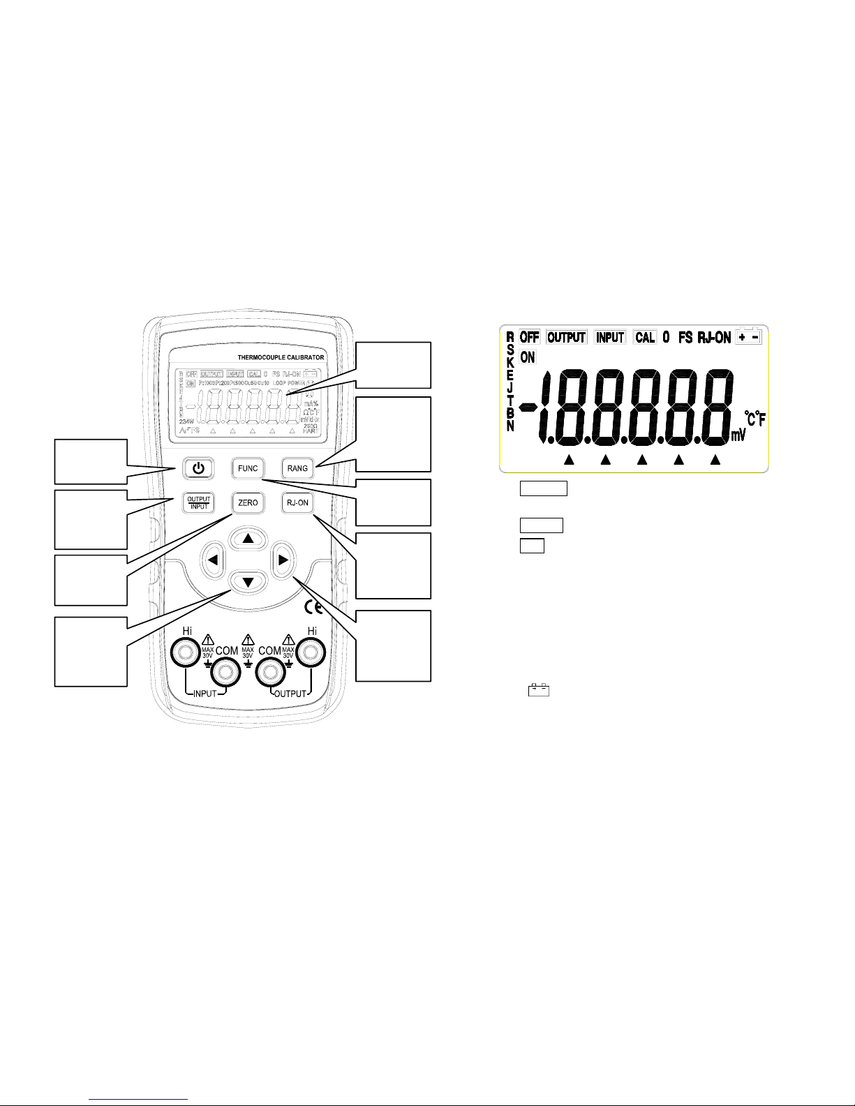
Victor VC02+ Technical manual

- 1 -
Operation Instruction
for Thermocouple Calibrator

- 2 -
WARRANTY
Our company warrants to the original purchaser that each product it manufactures will be free from defects in
material and workmanship under normal use and service for a period of one year from date of purchase. Our company’s
warranty does not apply to fuses, test leads or any product which, in our company’ s opinion, has been misused, altered,
or damaged by accident or abnormal conditions of operation or handling.
To obtain warranty service, contact your nearest Service Center (or send the product, with a description of the
difficulty, and postage prepaid, to the nearest Service Center). Our company assumes no risk for the damage in transit.
Our company will, at its option, repair or replace the defective product free of charge or refund your purchase price.
However, if our company determines that the failure was caused by misuse, alterations, accident or abnormal condition
of operation or handing, you will be billed for the repair and the repaired product will be returned to you transportation
prepaid.
SHIPPING TO MANUFACTURER
FOR REPAIR OR ADJUSTMENT
All shipment of our company’s instruments should be made via United Parcel Service or “Best Way” prepaid. The
instrument should be shipped in the original carton; or if it is not available, use any suitable container that is rigid and of
adequate size. If a substitute container is used, the instrument should be wrapped in paper and surrounded with at least

- 3 -
four inches of excelsior or similar shock-absorbing material.
CLAIM FOR DAMAGE IN SHIPMENT
TO ORIGINAL PURCHASER
The instrument should be thoroughly inspected immediately upon original delivery to purchaser. All material in the
container should be checked against the enclosed packing list. The manufacturer will not be responsible for shortages
against the packing sheet unless notified immediately.
If the instrument is damaged in any way, a claim should be filed with the carrier immediately. (To obtain a quotation
to repair shipment damage, contact the nearest Service Center.) Final claim and negotiations with the carrier must be
completed by the customer.

- 4 -
INDEX
P a g e
1. Safety Information………………………………………………………………………………………………………… 1
2. Instrument Panel Layout and Functions……………………………………………………………………………… 2
3. Instrument Maintenance………………………………………………………………………………………………… 3
4. Power-on/off of Instrument……………………………………………………………………………………………… 4
5. Output from Instrument……………………………………………………………………………………………………4
6. Instrument Measurement…………………………………………………………………………………………………6
7. Setting Function………………………………………………………………………………………………………… 7
8. Performance Index……………………………………………………………………………………………………… 7
9. Notice of the Manual………………………………………………………………………………………………………10

- 5 -
Section One Safe Use
To ensure safe use, the meter and manual employ
the following symbols:
Warning identifies conditions and actions that
may pose hazard(s) to the user and
avoid methods.
Caution identifies conditions and actions that
may damage the meter or the
equipment under test and avoid
methods.
Note reminds Users of knowledge of symbols
for the operation and explanations of the
features.
To avoid possible electric shock or any other
dangers, please do follow the under-mentioned rules:
Warning
• Do not operate the meter around explosive gas,
vapor, or dust, which is extreme dangerous.
• Never apply voltage exceeding 30V between any
two terminals and earth ground terminals.
Caution
• Do not open the meter’s case except for the
professional technicians.
• Use a damp cloth with neutral detergent for
cleaning the meter periodically. Do not use abrasives
or solvents.
Note
• To ensure accuracy, preheat for 5 minutes after
power-on.
• Please contact the manufacture or dealers if the
Users have higher accuracy requirement.
Section Two Components and Functions of Meter’s
Panel

- 6 -
Illustration for LCD display area
a) OUTPUT : indicates the meter is in output
state.
b) INTPUT :
indicates the meter is in input state.
c) CAL :indicates the meter is in calibration
state.
d) 0 FS : indicates the present calibrated
zero point or full point etc. when the meter is in
calibration state.
e) RJ- ON : indicates the meter has undergone
cold junction compensation work (See detailed
section).
f) : indicates the batteries are
exhausting and needs replacement (See
detailed section).
g) ▲:indicates present set output value.
h) mV、°C、℉ :
indicates the unit for present output
value.
LCD
display
power-on
key
input/out
put shift
key
output
clearing
ke
y
range
selection
key
function
key
thermocou
ple cold
compensat
ion key
τυ output
value set
key
πθ output
value set
key
input/outp
our
terminal

- 7 -
i) O N : indicates connection of output
signals.
j) R、S、K、E、J、T、B、N: indicates graduated no.
of thermocouple(TC).
Section Three Maintenance
This section provides some basic maintenance
procedures. Repair, calibration, and servicing not
covered in this manual must be performed by qualified
personnel. For maintenance procedures not described in
this manual, contact a Service Center.
(1)
General maintenance
zPeriodically wipe the case with a damp cloth and
detergent; do not use abrasives or solvents.
zTake out the batteries if the meter won’t be used for
a long time.
zDirt or moisture in the terminals can affect readings.
Clean the terminals as follows:
(1)Turn the meter off and remove all test leads.
(2)Shake out any dirt that may be in terminals.
(3)Soak a new swab with alcohol. Clean each
terminal with the swab.
(2)
Replacing the batteries
The meter is powered by two LR6 alkaline batteries
(AA). Warning
To avoid electrical shock or personal injury:
zRemove test leads from the meter before
opening the battery door.
zClose and latch the battery door before using
the meter.
Note
zThe new and old batteries can not be mixed.
zMake sure the battery’s odes are in accordance
with the marks illustrated in battery pool when
replacing them.
zTake out the batteries if the meter won’t be used
for a long time.
zDispose the old batteries in accordance with the
local law.
Replace the batteries as follows (See Figure 3-1):
1. Turn the rotary switch to OFF and remove the
test leads from the terminals;
2. Take off the support of the meter, remove the
battery door by a standard-blade screwdriver,
and then take off the battery case;
3. Replace with two new batteries;
4. Reinstall the battery case, spin the screws and
tighten screws.

- 8 -
Figure 3-1 replacing batteries
Section Four Power on/Power off the Meter
(
1
)
Turn on/off the meter
Press 〔power〕key to electrify the meter, and
repress〔power〕key for more than 1 second to cut off the
power.
When turning on the power, the meter starts to make
inner diagnose and display in full screen, and then
undertakes corresponding operation.
Note
To ensure correct electrifying operation, please wait
for 5 seconds to turn on the meter again after cutting off
the power.
(
2
)
Automatically turn off the power
The default factory value is set as: the meter will
automatically turn off if no operation has been made
within 15 miniutes.
The Users can set by themselves to choose whether
using this function or not (See the detailed section).
Section Five Output of the Meter
The meter generates DC current or thermocouple
simulate temperature by the Users from the
corresponding output terminals(OUTPUT).
Caution
Do not apply any voltage to output terminal;
otherwise damage to interior circuit may occur if the
voltage is not proper.
(
1
)
DC voltage output
1. Insert the testing probe into the jack of the meter’s
output terminal (OUTPUT), and connect the other
end with input terminal of the Users’ meter, see
Figure 5-1:
2. Press〔FUN〕key , select V/mV function, and display
‘V’ or ‘mV’ unit;
3. Press 〔RANG〕key, select 100.00mV or 1.0000V
range;
4. Press 〔τ〕/〔υ〕key, select output set bit;

- 9 -
Figure 5-1
5. Press 〔π〕/〔θ〕key , change the value of set bit, and
the value can carry or abdicate automatically, and
hold the key, the value will change constantly after
one second;
6. Press〔ZERO 〕key, the output will be set as
000.00mV or 0.0000V.
(2)
Thermocouple (TC )simulate output
1. Insert the testing probe into the jack of the meter’s
output terminal (OUTPUT) and connect the other
end with input terminal of the Users’ meter, see
Figure 5-1;
2. Press〔INPUT/OUTPUT〕key, select output function
3. Press 【FUN】 key , select thermocouple(TC)
function, and display ‘°C’ unit and ‘R’ graduation no.;
4. Press 〔RANG 〕key, select corresponding
graduation no.;
5. Press 〔τ〕/〔υ〕key, select output set bit;
6. Press〔π〕/〔θ〕key , change the value of set bit, and
the value can carry or abdicate automatically, and
hold the key, the value will change constantly after
one second.
7. Automatic compensation of cold junctions
When calibrating meter with temperature cold
junction compensation directly, press 〔RJ-ON〕key to
start the automatic compensation function of cold
junctions of this meter, and it will output the necessary
temperature thermoelectric force, and display ‘RJ-ON’.
(See detailed section for the accuracy of cold junction
compensation), and :
Output thermoelectric force = the corresponding
thermoelectric force of set temperature –the
corresponding thermoelectric force of room temperature
* The Users need to wait for 2 seconds when
starting the interior cold junction compensation of
the meter and the meter will make automatic
compensation every 10 seconds
* When the operation ambient temperature change,
the Users need to wait until the interior
compensation sensor stabilizes (about 10 minutes)
and then use
* if the Users do not use the automatic
compensation function of this meter, press the
〔RJ-ON〕key and the symbol‘RJ-ON’will not
display any more
8. Press〔ZERO〕key, the output will be set as 0000°C

- 10 -
(R、S graduation)、400°C(B graduation)、0000.0°C
(other graduation).
9. Press 〔℃/℉〕key , select Centigrade or Fahrenheit
unit.
Section Six Measurement
Warning
Usage: the maximum voltage allowed between the
terminals and within the terminals and the ground is
30V, any exceeding over this voltage may cause
damage to the meter and even make injury to
persons.
Caution
Usage: do not apply any voltage exceeding the
maximum allowed to the input terminals, which may
cause damage to the meter.
Usage: when connected to the measured meter,
please first cut off the electricity supply. A
connection to the measured meter with power may
cause damage of this meter.
Usage: pay particular attention to not to connect the
current signal to the input terminal, incorrect
connection may cause damage to this meter and
the meter under measured.
(
1
)
Measuring DC voltage
1. Insert the testing probe into the jack of the meter’s
input terminal (INPUT), and connect the other end
with output terminal of the Users’ meter, see Figure
6-1:
Figure 6-1
2. Press〔INPUT/OUTPUT〕key , and the LCD displays
‘INPUT’, ‘ON’, ‘mV’,indicating the meter is in input
state;
3. The meter starts to measure, and the LCD displays
‘000.00’ which indicates waiting and then displays
measurement result.
4. The refreshing rate of measurement is about twice
every second, and if the measured value exceeds
the measurement range, the LCD displays ‘OL’.
(2)
Measuring thermocouple(TC)
1. Insert the testing probe into the jack of the meter’s
input terminal (INPUT), and connect the other end
with output terminal of the Users’ meter, see Figure
6-1:

- 11 -
2. Press〔INPUT/OUTPUT〕key , and the LCD displays
‘INPUT’,indicating the meter is in input state;
3. Press【FUN】 key , select thermocouple(TC) function,
and display ‘°C’ unit and ‘R’ graduation no.;
4. Press〔RANG〕key, select corresponding graduation
no.;
5. The LCD displays ‘0000’ , indicating waiting and then
displays measurement result.And the refreshing rate
is approximately once a second, and if the measured
value exceeds the measurement range, the LCD
displays ‘OL’.
6. Automatic compensation of cold junctions
When calibrating meter with temperature cold
junction compensation directly, press 〔RJ-ON〕key to
start the automatic compensation function of cold
junctions of this meter, and :
Displayed temperature = the corresponding
temperature of input thermoelectric force + room
temperature
7. Press 〔℃/℉〕key , select Centigrade or Fahrenheit
unit.
Section Seven Function Setting
The following operation can change the automatic
power off function of the meter:
1. When the meter is in power-off state, press〔power〕
key and the LCD displays fully , loose〔power〕key
and pres〔RANG 〕key, the meter enters into
maintenance state and the LCD displays ‘AP –XX’
2. Press 〔θ〕key and the LCD displays symbol
‘AP-OF’, the meter stops automatically power-off
function ; The LCD displays symbol ‘AP-ON’, the
meter restores automatically power-off function, and
the meter exit from maintenance state if cutting off
the power again.
Section Eight Performance Index
Accuracy is specified for a period of one year after calibration, at 23±5ºC, with relative humidity to 75%.
Accuracy specifications are given as: ± ([% of reading] + [number of least significant digits]) (“Counts” refers
to the number of increments or decrements of the least significant digit).
Output function and technical index
Output Range Output range Resolution Accuracy Illustration
DCV 100mV
-10.00~110.00mV 0.01mV 0.05%+30uV Max. output
current ±2mA

- 12 -
1V -0.1000~1.1000V 0.1mV 0.05%+0.3mV
TC
R -40~1760℃1℃0.05%+3 (less than or equals to
100°C)
0.05%+2(more than 100°C)
Employs ITS-90
temperature
standard
The accuracy does
not include the
error of interior
temperature
compensation
sensor
The accuracy does
not include the
impact of interior
thermoelectric
force
S -20~1760℃1℃
RTD
B 400~1800℃1℃
0.05%+3 (less than or equals to
600°C)
0.05%+2(more than 600°C)
E -200.0~1000.0℃0.1℃
0.05%+20 (less than or equals to
-100°C)
0.05%+10(more than -100°C)
K -200.0~1370℃0.1℃
J -200.0~1200.0℃0.1℃
T -200.0~400.0℃0.1℃
N -200.0~1300.0℃0.1℃
Input function and technical index
Input Range Output range
Resolut
ion Accuracy Illustration
DC voltage
DCmV 100mV -10.00~110.00mV 0.01mV 0.05%+3 Input resistance:1MΩ
thermocouple
TC R -40°C~1760°C 1°C 0.05%+3(less than or equals to
100°C)
Input resistance :1MΩ
Employs ITS-90 temperature standard

- 13 -
S -200°C~1760°C 0.05%+2(more than 100°C)The accuracy does not include the error
of interior temperature compensation
sensor
The accuracy does not include the
impact of interior thermoelectric force
B 400°C~1800°C
0.05%+3(less than or equals to
600°C)
0.05%+2(more than 600°C)
K -200.0°C~1370.0°C
0.1°C
0.05%+20(less than or equals to
-100°C)
0.05%+10(more than -100°C)
E -200.0°C~1000.0°C
J -200.0°C~1200.0°C
T -200.0°C~400.0°C
N -200.0°C~1300.0°C
General feature
zpower : two 1.5V alkaline batteries(LR6)
zpower consumption : about 50m/3V
zmaximum allowed
voltage :30V(within terminals or between terminal and earth ground)
zoperation temperature
range :0°C~50°C
zoperation humidity
range :≤80%RH
zstorage temperature
range :≤- 10°C~55°C
zstorage humidity range : ≤90%RH
ztemperature coefficient : 0.1×(dedicated accuracy)%/℃(5℃~18℃、28℃~40℃)
zmeasurement : 180(L)×90(W)×47(D)mm(with protector)

- 14 -
zweight : about 500g
zaccessory : User’s Manual, industrial testing lead CF-36 (clips for probe)
zsafety : complies with IEC1010 (safety standard issued by International Electrician
Committee)
Section Nine Note for the Manual
zThe present operation instruction is subject to change without notice;
zThe content of the operation instruction is regarded as correct. Whenever any user finds its mistakes, omission,
etc., he or she is requested to contact the manufacturer;
zThe present manufacturer is not liable for any accident and hazard arising from the customer misuse or
inadvertent operation;
zThe functions described in this operation instruction should not be used as grounds to apply this product to a
particular purpose.
Table of contents
Other Victor Test Equipment manuals