Victron energy VE.Bus User manual

Manual
EN
Handleiding
NL
Manuel
FR
Anleitung
DE
Manual
ES
Appendix
VE.Bus Multi Control Panel


Copyrights 2008 Victron Energy B.V.
All Rights Reserved
This publication or parts thereof may not be reproduced in any form, by any method, for any
purpose.
For conditions of use and permission to use this manual for publication in other than the English
language, contact Victron Energy B.V.
VICTRON ENERGY B.V. MAKES NO WARRANTY, EITHER EXPESSED OR IMPLIED,
INCLUDING BUT NOT LIMITED TO ANY IMPLIED WARRANTIES OF MERCHANTABILITY OR
FITNESS FOR A PARTICULAR PURPOSE, REGARDING THESE VICTRON ENERGY
PRODUCTS AND MAKES SUCH VICTRON ENERGY PRODUCTS AVAILABLE SOLELY ON AN
“AS IS” BASIS.
IN NO EVENT SHALL VICTRON ENERGY B.V. BE LIABLE TO ANYONE FOR SPECIAL,
COLLATERAL, INCIDENTAL, OR CONSEQUENTIAL DAMAGES IN CONNECTION WITH OR
ARISING OUT OF PURCHASE OR USE OF THESE VICTRON ENERGY PRODUCTS. THE
SOLE AND EXCLUSIVE LIABILITY TO VICTRON ENERGY B.V., REGARDLESS OF THE
FORM OF ACTION, SHALL NOT EXCEED THE PURCHASE PRICE OF THE VICTRON
ENERGY PRODUCTS DESCRIBED HERE IN.
Victron Energy B.V. reserves the right to revise and improve its products as it sees fit. This
publication describes the state of this product at the time of its publication and may not reflect the
product at all times in the future
.


1
EN NL FR DE ES Appendix
1. Introduction
The VE.Bus Multi Control panel (VBMC) is the correct choice if you want to remotely control
a simple Multi system based on VE.Bus.
If more than 1 AC input has to be controlled by the panel or if the transfer currents exceed
the maximum of the VBMC, the Digital Multi Control (DMC) should be used instead.
Connecting the VBMC to your system is a simple procedure. In most cases just connecting
it with a RJ45 cable is sufficient and no extra set-up handling is required.
Note:
The VBMC is completely backwards compatible so it is also very well suitable to be used
with non VE.Bus systems. (The word “system” refers to an installation of one or more Multis
or Quattro’s.)
This manual describes only VE.Bus systems. Please contact Victron Energy if you need
specific information about using this panel with non-VE.Bus systems. To determine whether
or not your system is VE.Bus, check the firmware version in the Multi. All Multi firmware
versions 15xxyyy, 17xxyyy and 18xxyyy are non VE.Bus. (Quattro’s are always VE.Bus.)

2
2. Installation
Without external transfer switch
Installation of the VBMC in a VE.Bus system without external transfer relay is really only a matter
of connecting the interface cable. No special setup of the VBMC is needed. Scaling to the system
is done automatically.
(In the unlikely situation that the VBMC is set to a higher limit than is allowed for the system, the
system maximum is automatically taken. For example: In a system with a 30A VBMC in
combination with a 16 A Multi the shore current maximum is limited to 16A. Even in the case that
the VBMC is set to 25A.)
With external transfer switch
This paragraph deals with systems with 2 AC inputs built with a non-intelligent external transfer
switch. This paragraph can be skipped if you have a system with more than one AC input build
with VE.Bus. (For instance by using Quattro’s or by using Multis with the extended VE.Bus
functionality.)
If an external transfer switch is placed before the Multis then this switch determines which AC
source is used. The Multis do not have any information about the state of the switch. The VBMC
provides a way to specify different current limits for both AC sources.
To achieve this, the VBMC must have information about the state of the external transfer switch.
For this purpose a screw connector is placed at the backside of the VBMC.
Normally the VBMC will send the current set point as determined by the knob to the Multis. If
however the terminals of this screw connector are short circuited the VBMC sends a preconfigured
current limit to the Multis. Because this functionality is mainly used to connect a generator this
preconfigured current limit is called ‘generator current limit’ throughout this manual. Paragraph 4
describes how this limit can be changed.
The two terminals of the screw connector are to be connected to the external transfer switch. An
auxiliary relay of the external transfer switch is most common place to do so. Refer to the transfer
switch manual for more information.

3
EN NL FR DE ES Appendix
Wiring
To install your VBMC you will need:
•An UTP (Unshielded Twisted Pair) cable with two RJ45 connectors (to connect to
a Multi or Quattro) available in 5, 10, 15, 20, 25 and 30 meters.
•When using an external transfer switch you will also need two wires for
connecting the panel to the transfer switch. This connection can be made by
using 2 wires of 0.25 – 1.0mm². Refer to the transfer switch manual for more
information.

4
3. Using the VE.Bus Multi Control panel
The VBMC is used to remotely set the shore current, read out the status of your system and turn
on and off the Multis or Quattro’s.
3.1 Turning the system on and off
Use the switch on the front to turn the system on, off or to charger only operation.
3.2 Setting the system input current limit
The shore current is set by the control knob on the VBMC. Turn the knob to the desired value.
There are 2 models of the VBMC: a 16 Amp and a 30 Amp. Use the appropriate panel for your
system.
When PowerAssist is enabled there is a minimum AC input current limit of approximately 2-3Amp
per device. Setting a lower limit than this minimum will result in the minimum limit. This is normal
Multi/Quattro behavior. There is a feature in the Multi/Quattro that, when PowerAssist is enabled
and the shore current setting from the remote panel is zero amps, the internal transfer relay is
opened and the device starts inverting.
3.3 LED brightness
For your comfort, the brightness of the LEDs is controlled automatically using a light sensor. When
the ambient light level becomes lower the LEDs will be less bright which is more pleasant for the
eye and reduces power consumption.

5
EN NL FR DE ES Appendix
4. Configuring the VE.Bus Multi Control panel
In most cases the panel will function without extra configuration.
Only when using an external transfer switch or when using non-VE.Bus Multis the panel
needs to be configured. During configuration 2 parameters can be set.
1 The scaling factor
This parameter is for backwards compatibility only and needs to be set when using non-
VE.Bus Multis. Please contact Victron Energy for more information about connecting non-
VE.Bus Multis.
2 The generator current limit
This parameter needs only to be configured when using an external transfer switch and is
of no influence otherwise. The generator current limit can be set from 0 up to about 200
Amps.
The factory default value for the generator current limit is 16 Amps.
Important note:
Small 3000 rpm generator sets of certain brands will overheat when operating for long
periods at full load. In some cases the maximum current will have to be set at no more than
70 % of the rated maximum current. The current limit of 1500 rpm generator sets can in
general be set at around 90 % of the rated output current.
4.1 Procedure
Configuration of the 2 parameters is done in three steps. In each step a value 0-9 must be
programmed. During these steps the LEDs display information about the step number and the
value being programmed in this step.
4.1.1 Reading the LEDs
The remote panel has 2 columns of LEDs. During configuration each column represents 0-9
according to the table below.
(Each LED represents a value. 0
(off)
, 1
(blink)
or 2
(on)
. Add the values of the LEDs in a column to
obtain the values 0-8. All LEDs flashing indicates 9.)
Value 0 1 2 3 4 5 6 7 8 9
LED
indication
means LED is off, means LED is blinking, means LED is on

6
The left column denotes the current step (1, 2 or 3) while the right represents the value 0-9 being
programmed for this step.
STEP VALUE
4.1.2 Entering configuration mode
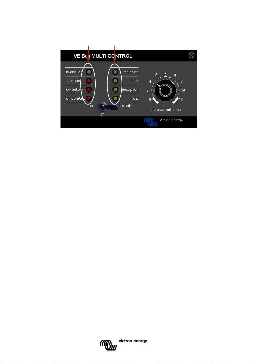
To enter the configuration mode press the button on the back of the panel until the bottom LED in
the left column starts flashing indicating step 1.
Note: The connected Multis or Quattro’s switch to ‘Inverter only’ when the configuration button is
pressed and during configuration mode.
4.1.3 Step 1
The scaling factor is configured in the first step. This parameter is not used in VE.Bus systems so
press the button again to proceed to step 2.
(The left LED column will “display” 2, indicating step 2.)
4.2.4 Step 2 and 3
Because the generator current limit range largely exceeds the 0-9 range we need two steps to
configure the generator current limit. By using 2 steps we can create a value from 0-99. This is
done as follows: In step 2 we program the tens and in step 3 we program the units. For example to
configure a value of 68 we program 6 in step 2 and 8 in step 3.
Important: A range of 0-99A for the generator current limit is not enough to cover all systems.
Therefore the panel multiplies the programmed value by 2 to obtain the generator current limit.
So programming for instance 95 (in steps 2 a 9 and in step 3 a 5) will result in a generator current
limit of 2x95=190A.
Steps to perform:
•Determine the required generator current limit.
•Divide this value by 2 to obtain the value which must be programmed during step 2 & 3.
•Turn the knob until the right LED column “displays” the correct value for step 2.
•Press the button to proceed to step 3. (The left LED column will “display” the value 3)
•Turn the knob until the right LED column “displays” the correct value for step 3.
•Press the button to exit configuration mode and make the new settings effective.
(The panel will function normally displaying the state of the connected system)

7
EN NL FR DE ES Appendix
Example for a 230V/4kVA generator (3000 rpm):
A 4kVA/230V generator can supply a maximum current of 17,4A. Using the 70%
safety margin we will set the generator current limit to 12A. To set the
configuration, using either a 16A or 30A panel, do the following:
•Press and hold the configuration button until the bottom LED
in the left column
starts flashing indicating step 1.
This step can be ignored because we assume VE.Bus Multis.
•Press the button to go to the next step.
(The lower left
LED
will turn on indicating step 2.)
•Determine the value for step 2 by dividing the required generator current by 2.
12/2 = (0)6.
Because this is lower than 10 the value to be set during step 2 is 0.
The value to be set during step 3 is 6.
•Turn the knob until all LEDs in the right columns are off. Setting the value for step
2 to 0.
•Press the button to go to step 3.
•Turn the knob until the bottom 3 LEDs in the right columns are on. Setting the
value for step 3 to 6.
•Press the button to finalize the configuration.


1
EN NL FR DE ES Appendix
1. Introductie
Het VE.Bus Multi Control paneel (VBMC) is de juiste keuze als u op afstand een simpel
Multi systeem gebaseerd op VE.Bus wilt bedienen. Indien meer dan 1 AC input door het
paneel bestuurd moet worden of indien de overneemstromen het maximum van de VBMC
overschrijden, dient u het Digital Multi Contol paneel (DMC) te gebruiken.
De VBMC met uw systeem verbinden is een eenvoudige procedure. In de meeste gevallen
is beide met elkaar verbinden doormiddel van een RJ45 kabel voldoende.
Opmerking:
The VBMC is volledig backwards compatible. Dit houdt in dat het ook geschikt is om te
gebruiken met non-VE.Bus systemen (het woord “systeem” verwijst naar een installatie van
één of meerdere Multi’s of Quattro’s).
Deze handleiding beschrijft alleen VE.Bus systemen. Indien u specifieke informatie nodig
heeft over het gebruik van dit paneel met non-VE.Bus systemen kunt u contact opnemen
met Victron Energy. Controleer de firmware versie in de Multi om vast te stellen of uw
systeem wel of niet VE.Bus is. De Multi firmware versies 15xxyyy, 17xxyyy and 18xxyyy zijn
non-VE.Bus. Quattro’s zijn altijd VE.Bus.

2
2. Installatie
Zonder externe omschakelautomaat
Het enige wat u moet doen om de VBMC te installeren in een VE.Bus systeem zonder externe
omschakelautomaat is de interface kabel verbinden. Er is geen speciale set-up van de VBMC
nodig.
Als in alle onwaarschijnlijkheid de VBMC toch ingesteld is op een hoger limiet dan dat van het
systeem, dan zal automatisch het maximum van het systeem gehanteerd worden. Bijvoorbeeld: in
een systeem met een 30A VBMC en een 16A Multi staat het walstroom maximum gelijk aan 16A.
Zelfs als de VBMC op 25A ingesteld is.
Met externe omschakelautomaat
Deze paragraaf betreft systemen met twee AC inputs die gebouwd zijn met een niet intelligente
externe omschakelautomaat. U kunt deze paragraaf overslaan indien u een systeem heeft met
meer dan één AC input dat gebouwd is met VE.Bus. Bijvoorbeeld door het gebruik van Quattro’s
of door het gebruik van Multi’s met de VE.Bus functionaliteit.
Als er een externe omschakelautomaat geplaatst is voordat er Multi’s geplaatst zijn bepaalt de
automaat welke AC bron gebruikt wordt. De Multi’s hebben geen informatie over de toestand van
de automaat. De VBMC biedt een manier om verschillende stroomgrenzen in te stellen voor beide
AC bronnen.
Om dit te bereiken heeft de VBMC informatie nodig over de toestand van de externe
omschakelautomaat. Hiervoor is er een connector aan de achterzijde van de VBMC geplaatst.
Normaliter stuurt de VBMC de met de controleknop ingestelde stroomwaarde naar de Multi’s.
Indien de connector wordt kortgesloten zal de VBMC een ingestelde stroomgrens aan de Multi’s
doorgeven. Deze stroomgrens wordt in deze handleiding de ‘generator stroomgrens’ genoemd
omdat deze functionaliteit voornamelijk gebruikt wordt om generatoren te verbinden. Paragraaf 4
beschrijft hoe u deze grens kunt wijzigen.
De twee klemmen van de connector moeten verbonden worden met de externe
omschakelautomaat. Een hulprelais van de externe omschakelautomaat is de gebruikelijke plaats
hiervoor. Kijk voor meer informatie in de handleiding van de omschakelautomaat.

3
EN NL FR DE ES Appendix
Bedrading
Om uw VBMC te installeren heeft u het volgende nodig:
•Een UTP (Unshielded Twisted Pair) kabel met twee RJ45 connectors (om het
paneel te verbinden met een Multi of Quattro); beschikbaar in 5, 10, 15, 20, 25 en
30 meter.
•Als u een externe omschakelautomaat gebruikt heeft u tevens twee draden nodig
om het paneel met de automaat te verbinden. Deze verbinding kunt u
bewerkstelligen door 2 draden van 0.25 – 1.0mm² te gebruiken. Kijk voor meer
informatie in de handleiding van de omschakelautomaat.

4
3. Het VE.Bus Multi Control paneel gebruiken
U kunt de VBMC gebruiken om op afstand de walstroom in te stellen, de status van uw systeem af
te lezen en uw Multi’s of Quattro’s aan/uit te zetten.
3.1 Uw systeem aan en uit zetten
U kunt het systeem met de schakelaar aan de voorkant aan/uit of op alleen laden zetten.
3.2 De systeem input stroomgrens instellen
U kunt de walstroom bepalen doormiddel van de controleknop op de VBMC. Draai de knop om de
gewenste waarde te kiezen. Er zijn twee VBMC modellen: een 16A en een 30A. Gebruik het
paneel dat geschikt is voor uw systeem.
Als PowerAssist is ingeschakeld is er een minimum AC input stroomgrens van omstreeks 2-3A
per apparaat. Kiezen voor een lagere grens dan dit minimum resulteert alsnog in hantering van
het minimum. Dit is gebruikelijk Multi/Quattro gedrag. Er is een functionaliteit in de Multi/Quattro
die ervoor zorgt dat wanneer PowerAssist ingeschakeld is, en de ingestelde walstroom op het
paneel op nul ampère staat, de interne omschakelautomaat wordt geopend en het apparaat begint
om te vormen.
3.3 LED helderheid
Voor uw comfort wordt de helderheid van de LED’s automatisch bepaald doormiddel van een
lichtsensor. Als de omgevingslichtsterkte lager wordt zal de helderheid van de LED’s ook dalen.
Dit is prettig voor het oog en verminderd tevens het stroomverbruik.

5
EN NL FR DE ES Appendix
4. Het VE.Bus Multi Control paneel configureren
In de meeste gevallen werkt het paneel zonder extra configuratie.
Alleen als u een externe omschakelautomaat of non-VE.Bus Multi’s gebruikt dient u het
paneel te configureren. Tijdens deze configuratie kunt u twee parameters instellen.
1 De schaalwaarde
Deze parameter moet alleen ingesteld worden indien u non-VE.Bus Multi’s gebruikt. Neem
alstublieft contact op met Victron Energy indien u meer informatie over het verbinden van
non-VE.Bus Multi’s wenst.
2 De generator stroomgrens
Deze parameter hoeft alleen geconfigureerd te worden indien u een externe
omschakelautomaat gebruikt. Is dit niet het geval dan heeft deze parameter geen invloed.
De generator stroomgrens kan ingesteld worden op 0 tot ongeveer 200 Ampère. De
standaard fabriekswaarde is 16 Ampère.
Belangrijke opmerking:
Kleine 3000 RPM generatorsets van bepaalde merken raken oververhit als ze gedurende
lange periodes met maximale belasting draaien. In sommige gevallen moet de
maximumstroom op maximaal 70% van de nominale maximumstroom ingesteld worden. De
stroomgrens van 1500 RPM generatorsets kan over het algemeen ingesteld worden op
rond de 90% van de nominale outputstroom.
4.1 Procedure
Het configureren van de 2 parameters wordt gedaan in drie stappen. Bij elke stap moet er een
waarde van 0-9 geprogrammeerd worden. Tijdens deze stappen geven de LED’s informatie weer
over het stap nummer en de waarde die geprogrammeerd wordt.
4.1.1 De LED’s lezen
Het paneel heeft twee kolommen met LED’s. Tijdens de configuratie vertegenwoordigt elke kolom
0-9 zoals in de onderstaande tabel wordt weergegeven.
(Elke LED belichaamt een waarde. 0
(uit)
, 1
(knipper)
of 2
(aan)
. Voeg de waardes van de LED’s toe in een
kolom om de waardes 0-8 te verkrijgen. Alle LED’s knipperen betekent waarde 9.)
Waarde 0 1 2 3 4 5 6 7 8 9
LED
indicatie
LED is uit, LED knippert, LED is aan

6
De linkerkolom geeft de huidige stap aan (1, 2 of 3). De rechterkolom geeft de waarde (0-9) aan
die tijdens de huidige stap geprogrammeerd wordt.
STAP WAARDE
4.1.2 Configuratiemodus
Om de configuratiemodus te starten dient u op de knop aan de achterzijde van het paneel te
drukken. Zodra de onderste LED in de linkerkolom begint te knipperen kunt u met stap 1
beginnen.
Opmerking: De verbonden Multi’s of Quattro’s schakelen naar ‘Inverter only’ zowel wanneer de
configuratie knop ingedrukt wordt als tijdens de configuratiemodus.
4.1.3 Stap 1
De schaalwaarde wordt geconfigureerd in de eerste stap. Deze parameter wordt niet gebruikt in
VE.Bus systemen dus druk opnieuw op de configuratie knop om verder te gaan naar stap 2.
(De linker LED kolom zal 2 weergeven.)
4.2.4 Stap 2 en 3
Omdat de generator stroomgrens ver boven de 9 kan liggen zijn er twee stappen nodig om de
generator stroomgrens te configureren. Zodoende kunt u een waarde van 0-99 instellen. In stap 2
programmeert u het eerste cijfer en in stap 3 het tweede cijfer. Indien u bijvoorbeeld een waarde
van 68 wilt programmeren, stelt u 6 tijdens stap 2 en 8 tijdens stap 3 in.
Belangrijk: De waardes 0-99A voor de generator stroomgrens bedekken niet alle systemen.
Daarom verdubbeld het paneel de geprogrammeerde waarde om de generator stroomgrens te
verkrijgen. Dus als u bijvoorbeeld 95 programmeert (9 in stap 2 en 5 in stap 3), resulteert dit in
een generator stroomgrens van 2x95=190A.

7
EN NL FR DE ES Appendix
Te ondernemen stappen:
•Bepaal de vereiste generator stroomgrens.
•Deel deze waarde door 2 om zodoende de waarde te verkrijgen die
geprogrammeerd moet worden tijdens stap 2 & 3.
•Draai de knop totdat de rechter LED kolom de juiste waarde voor stap 2
weergeeft.
•Druk op de knop om verder te gaan met stap 3 (de linker LED kolom zal de
waarde 3 weergeven).
•Draai de knop totdat de rechter LED kolom de juiste waarde voor stap 3
weergeeft.
•Druk op de knop om de configuratiemodus af te sluiten en de nieuwe instellingen
op te slaan. (Het paneel zal normaal functioneren en de status van het
verbonden systeem weergeven).
Voorbeeld voor een 230V/4kVA generator (3000 RPM):
Een 230V/4kVA generator kan maximaal 17,4A stroom leveren. Omdat we de
veiligheidsmarge van 70% gebruiken, stellen we de generator stroomgrens in op
12A. Om de configuratie in te stellen, met een 16A ofwel een 30A paneel, doe het
volgende:
•Houd de configuratieknop ingedrukt totdat de onderste LED in de linkerkolom
begint te knipperen – dit geeft aan dat stap 1 is bereikt.
U kunt deze stap negeren omdat we uitgaan van VE.Bus Multi’s.
•Druk op de knop om naar de volgende stap te gaan.
(De LED linksonder zal aangaan wat aangeeft dat stap 2 is bereikt).
•Bepaal de waarde voor stap 2 door de benodigde generatorstroom te delen door twee.
12/2 = (0)6.
Omdat dit lager is dan 10 staat de waarde die ingesteld moet worden tijdens stap 2
gelijk aan 0.
De waarde die ingesteld moet worden tijdens stap 3 is 6.
•Draai de knop totdat alle LED’s in de rechterkolom uit zijn. Zodoende stelt u de waarde
voor stap 2 in op 0.
•Druk op de knop om naar stap 3 te gaan.
•Draai de knop totdat de onderste LED’s in de rechterkolom aan zijn. Zodoende stelt u
de waarde voor stap 3 in op 6.
•Druk op de knop om de configuratie af te ronden.

Other manuals for VE.Bus
2
This manual suits for next models
1
Table of contents
Languages:
Other Victron energy Control Panel manuals

Victron energy
Victron energy Skylla-i Control GX User manual

Victron energy
Victron energy Blue Power BMV-602 User manual

Victron energy
Victron energy Digital Multi Control User manual

Victron energy
Victron energy VE.Net Blue Power Panel User manual

Victron energy
Victron energy Color Control GX User manual

Victron energy
Victron energy Color Control GX User manual

Victron energy
Victron energy Color Control GX User manual

Victron energy
Victron energy CCGX User manual