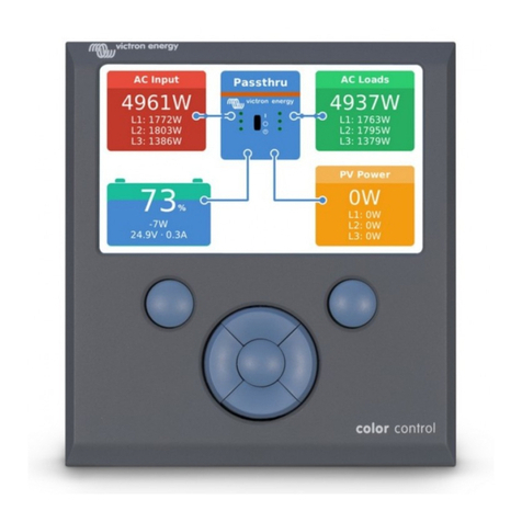
Victron energy Color Control GX User manual

2020-11-10 02:37 1/58 Color Control GX manual
Victron Energy - https://www.victronenergy.com/live/
Color Control GX manual
The Color Control GX (CCGX) sits at the heart of your energy installation. All the other system-
components - such as inverter/chargers, solar chargers, and batteries - are connected to it. The CCGX
ensures that they all work in harmony.
Monitoring can be done either with the CCGX in front of you - or from anywhere in the world using an
internet connection and the VRM Website
The CCGX also provides Remote firmware updates and even allows the settings to be Changed
Remotely.
The Color Control GX is part of the GX product family. GX products are Victron's state-of-the-art
monitoring solution that run our Venus OS operating system.

Last update: 2020-08-19 12:10 ccgx:start https://www.victronenergy.com/live/ccgx:start?rev=1597831811
https://www.victronenergy.com/live/ Printed on 2020-11-10 02:37
All the information in this manual refers to the latest software. Your device will update itself to the
latest version automatically. Check our blog posts to see that your device has the latest
firmware:https://www.victronenergy.com/blog/category/firmware-software/
1. Installation
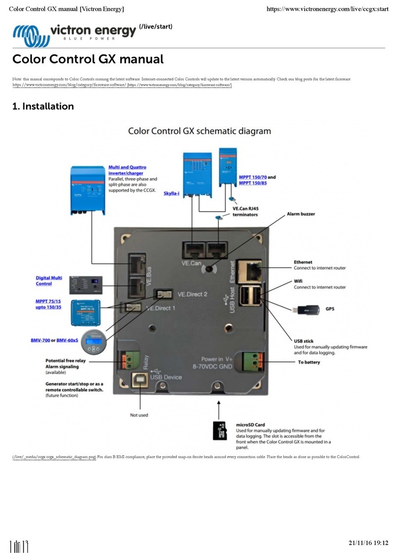
1.1 Overview of connections
1.2 Snap-on ferrite beads for class B EMI compliance
In order to reduce Electromagnetic emissions in compliance with class B EMI you should place the
provided snap-on ferrite beads around every connection cable as close as possible to the Color
Control.
HQ1700 and later
For serial numbers HQ1700 and later, mount a single snap-on ferrite bead (supplied with the unit)

Last update: 2020-08-19 12:10 ccgx:start https://www.victronenergy.com/live/ccgx:start?rev=1597831811
https://www.victronenergy.com/live/ Printed on 2020-11-10 02:37
1.3 Power
Power the device using the Power in V+ connector. It accepts 8 to 70 V DC. The device will not power
itself from any of the network connections. The supplied DC power cable includes an inline 3.15 A
slow blow fuse.
Powering in systems with VE.Bus BMS
When the CCGX is used in an installation with a VE.Bus BMS, connect the Power in V+ on the CCGX to
the terminal labelled 'Load disconnect' on the VE.Bus BMS. Connect both negative leads to the
negative stub of a common Battery.
A Cautionary word about Powering from the AC-out terminal of a VE.Bus Inverter, Multi or
Quattro:
If you power the CCGX from an AC adaptor connected to the AC-out port of any VE.Bus product

2020-11-10 02:37 5/58 Color Control GX manual
Victron Energy - https://www.victronenergy.com/live/
(Inverter, Multi or Quattro), then a deadlock will occur after the VE.Bus products are powered-down
for any reason (after any operational fault or during a black start). The VE.Bus devices will not boot-up
until the CCGX has power …but the CCGX will not boot-up until it has power. This deadlock can be
rectified by briefly unplugging the CCGX VE.Bus cable at which point you will observe the VE.Bus
products will immediately begin to boot-up.
Or a modification can be done to the RJ45 cabling. See FAQ Q20 for more information about this.
Note that both with or without above modification, powering the monitoring equipment with the AC-
out of an inverter/charger (ofcourse) has the disadvantage that all monitoring is shut down when
there is a problem that causes the inverter/charger to shut down. Examples are Inverter overload,
high temperature or low battery voltage. It is therefore recommended to power the GX device from
the battery.
Isolation
Because the CCGX is connected to many different products, please ensure that proper care is taken
with isolation to prevent ground loops. In 99% of installations this will not be a problem.
The VE.Bus ports are isolated
The VE.Direct ports are isolated
The VE.Can ports are isolated
The USB ports are not isolated. Connecting a Wi-Fi Dongle or GPS Dongle will not create a
problem as it is not connected to another power supply. Even though there will be ground loop
when you mount a separately-powered USB hub, during extensive testing we have not found
that it caused any issues.
The Ethernet port is isolated, except for the shield: use unshielded UTP cables for the Ethernet
network
Extending USB ports by use of a self-powered USB hub
Although the number of USB ports can be extended by using a hub, there is a limit to the amount of
power that the onboard USB port can provide. When extending the number of USB ports, we
recommend you always use powered USB hubs. And to minimize the chance of issues, be sure to use
good-quality USB hubs. As Victron also offers a VE.Direct to USB adapter, you can use this
arrangement to increase the number of VE.Direct devices you can connect to your system, please see
this document for the limit of how many devices can be attached to various different GX devices.
1.4 Connecting Victron products
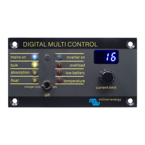
1.4.1 Multis/Quattros/Inverters (VE.Bus products)
In order to keep this document short we are going to refer to all Multis, Quattros and Inverters as
VE.Bus products.
The earliest version of the VE.Bus devices which can be connected to the CCGX is 19xx111 or
20xx111, which were released in 2007. VE.Bus firmware 26xxxxx and 27xxxxx are also supported

Last update: 2020-08-19 12:10 ccgx:start https://www.victronenergy.com/live/ccgx:start?rev=1597831811
https://www.victronenergy.com/live/ Printed on 2020-11-10 02:37
…but 18xxxxx is not.
Note that it is not possible to use the Remote On/Off (header on the VE.Bus control PCB) in
combination with a CCGX. There should be wire between the left and middle terminal, as it is when
shipped from the factory. In case a wired switch that disables the system is required, use the Safety
Switch Assistant.
Single VE.Bus products
To connect a single VE.Bus product, connect it to one of the VE.Bus sockets on the back of the CCGX.
Both sockets are identical, use either one. Use a standard RJ45 UTP cable, see our pricelist.
Parallel, split- and three-phase VE.Bus systems
To connect multiple VE.Bus products, configured as a parallel, split-phase or three phase VE.Bus
system, connect either the first or the last VE.Bus product in the chain to either one of the VE.Bus
sockets on the back of the CCGX. Use a standard RJ45 UTP cable, see our pricelist.
Systems consisting of five or more VE.Bus products, connected to a CCGX with serial number HQ1628
or earlier require the 'CCGX dongle for large VE.Bus systems (Product Number: BPP900300100).
VE.Bus systems with Lithium batteries and a VE.Bus BMS
Connect the CCGX to the socket labelled ‘MultiPlus/Quattro’, or to one of the Multis/Quattros in
the system. Do not connect it to the Remote panel socket on the VE.Bus BMS.
Note that it will not be possible to control the On/Off/Charger Only switch. This option is
automatically disabled in the CCGX menu when a VE.Bus BMS is used. The only way to control a
Multi or Quattro when used with a VE.Bus BMS is to add a Digital Multi Control to the system.
Setting the input current limit is possible in systems with a VE.Bus BMS.
Combining MultiPlus/Quattro with a VE.Bus BMS and a Digital Multi Control is possible. Simply
connect the Digital Multi Control to the RJ-45 socket on the VE.Bus BMS labelled Remote panel.
To allow auto-power-down in the CCGX in case of a low battery, make sure the CCGX is powered
via the VE.Bus BMS: connect Power in V+ on the CCGX to Load disconnect on the VE.Bus BMS.
And connect both negative leads to the negative stub of a common Battery.
Combining the CCGX with a Digital Multi Control
It is possible to connect both a CCGX and a Digital Multi control to a VE.Bus system. The ability to
switch the product On, Off or set it to Charger Only via the CCGX will be disabled. The same applies to
the input current limit: when there is a Digital Multi Control in the system, the input current limit
which is set at that control panel will be the master-setting, and changing it on the CCGX will not be
possible.
Connecting multiple VE.Bus systems to a single CCGX
Only one VE.Bus system can be connected to the VE.Bus ports on the back of the CCGX. The
professional way to to monitor more systems is to add a second CCGX.
If you do require to connect more than one system to the same CCGX, use an MK3-USB. Functionality
will be limited:
Only the system connected to the built-in VE.Bus ports is used to generate the data on the
Overview pages.
All connected systems will be visible on the Device-list
All connected systems will be taken into account for Energy consumption and distribution

2020-11-10 02:37 7/58 Color Control GX manual
Victron Energy - https://www.victronenergy.com/live/
calculations (kWh graphs on VRM)
Only the system connected to the built-in VE.Bus ports is used for the Generator start/stop logic
The CCGX will not send proper data to VRM any more. The Venus GX does send information of
both systems to VRM: its therefor better to use a Venus GX for systems like this.
In case of an ESS system, only the system connected to the built-in VE.Bus ports is used in the
ESS mechanisms. The other one is displayed in the device list only.
Alternatively the VE.Bus to VE.Can interface (ASS030520105) can be used. Add one for each
additional system. Note that we advise against it; this interface is a deprecated product. Make sure
that the VE.Can network is terminated and powered. For powering the VE.Can network, see Q17 in our
data communication whitepaper.
1.4.2 Battery Monitor BMV-700 series; and MPPTs with a VE.Direct port
Either one or two compatible products can be connected directly on the back of the CCGX using a
standard VE.Direct cable. There are two types of VE.Direct cable available:
Straight VE.Direct cables, ASS030530xxx1.
VE.Direct cables with an angled connector on one end. These are designed to minimize the2.
required depth behind a panel, ASS030531xxx
VE.Direct cables have a maximum length of 10 metres. It is not possible to extend them. If longer
lengths are required, use the VE.Direct to VE.Can interface. Note that this only works for BMV700 and
BMV702. Not for the BMV712, MPPT solar chargers and Inverters with a VE.Direct port. See next
paragraph for more information on that VE.Can interface.
Connecting more than two devices to your CCGX using VE.Direct
First of all, note that the maximum of VE.Direct devices that can be connected is 5 for the CCGX. How
they are connected, so direct, via USB or via CAN, does not change the maximum. See here for the
maximum limit on Venus GX, Octo GX, and other GX Devices.
Then, these are the options on how to connect more VE.Direct products than available VE.Direct
ports:
Option 1: Use the VE.Direct to USB interface. The CCGX has two USB ports. Use a USB-hub when
more than two USB ports are required.
Option 2: (Only!) the BMV700 and BMV702 can also be connected using the VE.Direct to VE.Can
interface. Note that the BMV712, MPPTs and VE.Direct Inverters cannot be connected using this
canbus interface as it does not translate their data into canbus messages. When using the
VE.Direct to VE.Can interface, make sure that the VE.Can network is terminated, and also
powered. For powering the VE.Can network, see Q17 in our data communication whitepaper.
Lastly, note that this canbus interface is deprecated.
Notes about older VE.Direct MPPTs
The MPPTs need to run firmware version v1.09 or later. See the Victron Professional website
https://professional.victronenergy.com/ to obtain files and for update instructions.
An MPPT 70/15 needs to be from year/week 1308 or later. Earlier 70/15s are not compatible
with the CCGX, and unfortunately upgrading the MPPT firmware will not help. To find the
Last update: 2020-08-19 12:10 ccgx:start https://www.victronenergy.com/live/ccgx:start?rev=1597831811
https://www.victronenergy.com/live/ Printed on 2020-11-10 02:37
year/week number of your model, look for the serial number which is printed on a label on its
back. For example number HQ1309DER4F means 2013, week 09.
1.4.3 Skylla-i, Lynx Shunt VE.Can, Lynx Ion + Shunt and MPPTs with a VE.Can port
To connect a product with a VE.Can port, use a standard RJ45 UTP cable. (Available with straight and
elbow connectors)
Don't forget to terminate the VE.Can network at both ends using a VE.Can terminator. A bag with two
terminators is supplied with each VE.Can product. They are also available separately.
Other notes:
In order to work with the CCGX an MPPT 150/70 needs run firmware v2.00 or newer.1.
You can combine a Skylla-i control panel with a CCGX.2.
You can combine a Ion Control panel with a CCGX.3.
The Skylla-i, Lynx Shunt VE.Can, Lynx Ion + Shunt and the MPPTs with a VE.Can port all power4.
the VE.Can network …so it won't be necessary to power the VE.Can network separately in these
circumstances. All the protocol converters - for example the VE.Bus to VE.Can interface; and the
BMV to VE.Can interface, do not power the VE.Can network.
1.4.4 BMV-600 series
Connect the BMV-600 using the VE.Direct to BMV-60xS cable supplied. (ASS0305322xx)
1.4.5 DC Link box
Connect the DC Link box, using the RJ-12 cable supplied. Then connect the BMV-700 to the CCGX -
see 1.2.2 above for instructions.
1.4.6 VE.Can Resistive Tank Sender Adapter
See its page and manual on our website for details about the Adapter.
To connect a product with a VE.Can port, use a standard RJ45 UTP cable.
Don't forget to terminate the VE.Can network on both ends using a VE.Can terminator. A bag with two
terminators is supplied with each VE.Can product. They are also available separately
(ASS030700000). (Available with straight or elbow connectors.)
Make sure that the canbus is powered, see the Power chapter in the Tank Sender Adapter manual for
details.
1.5 Connecting a PV Inverter
Measuring the output of a PV Inverter will provide the user with an overview of both actual power

2020-11-10 02:37 9/58 Color Control GX manual
Victron Energy - https://www.victronenergy.com/live/
balance and the energy distribution. Note that these measurements are only used to display
information. They are not needed, nor used, by the installation for its performance.
Besides monitoring, the GX device can also curtail some types and brands of PV Inverters, ie. reduce
their output power. This is used, and required, for the ESS Zero feed-in feature.
Direct connections
Type Zero feed-in Details
Fronius Yes LAN Connection, see GX - Fronius manual
SMA No LAN Connection, see GX - SMA manual
SolarEdge No LAN Connection, see GX - SolarEdge manual
ABB Yes LAN Connection, see GX - ABB manual
Using a meter
For PV Inverters that cannot be interfaced digitally, a meter can be used:
Type Zero feed-
in Details
AC Current Sensor No Connected to inverter/charger analog input. Lowest cost - least
accurate. AC Current Sensor Manual
Energy Meter No wired to the CCGX, or connected wirelessly using our Zigbee to
USB/RS485 interfaces. See the Energy Meters start page
Wireless AC
sensors No See the Wireless AC Sensor manual - Discontinued
1.6 Internet connectivity
Connect the CCGX to the internet to get all the advantages of the VRM Portal. The CCGX sends data
from all connected products to the VRM portal - from where you can monitor energy usage, view the
current status of connected products, configure email alarms and download data in CSV and Excel
formats.
To monitor this data from your smartphone or tablet download the iOS or Android VRM App.
In addition to remote monitoring, an active internet connection allows the CCGX to regularly check for
a new firmware versions - which will be automatically downloaded and installed.
There are several ways to connect a CCGX to the internet:
Run a network cable between a router and the CCGX Ethernet LAN port
Connect to a router wirelessly using a USB Wi-Fi dongle plugged into the CCGX
Via the mobile (cellular) network, using a 3G or 4G router
GX GSM - a cellular USB modem
USB Tethering on a mobile phone
This video explains how to connect LAN, WiFi and a GX GSM:

Last update: 2020-08-19 12:10 ccgx:start https://www.victronenergy.com/live/ccgx:start?rev=1597831811
https://www.victronenergy.com/live/ Printed on 2020-11-10 02:37
Video
The chapters below describe the options in detail.
1.6.1 Ethernet LAN port
When you connect an ethernet cable between a router and CCGX, the Settings>Ethernet page of your
CCGX will confirm connection.
1.6.2 Wi-Fi USB dongle
Using a Wi-Fi dongle it is possible to connect to WEP, WPA and WPA2 secured networks. There are five
supported USB Wi-Fi dongles. Two of them are also available from stock at Victron Energy:
Partno. BPP900100200 - CCGX WiFi module simple (Nano USB), small, low cost.
Partno. BPP900200300 - Asus USB-N14, slightly higher cost and also better reception than the
Nano USB. Supported since software version 2.23.
WiFi modules that are no longer available, but still supported, are:
Partno. BPP900200100 - Startech USB300WN2X2D
Partno. BPP900100100 - Zyxel NWD2105
Partno. BPP900200200 - Gembird WNP-UA-002, slightly higher cost and also better reception.

2020-11-10 02:37 11/58 Color Control GX manual
Victron Energy - https://www.victronenergy.com/live/
Although other Wi-Fi dongles may work, they have not been tested and we do not offer support for
other dongles.
The Wi-Fi menu shows the available networks. When a network is selected, it is possible to fill in the
password (if the password is not already known) to connect to the network. Setting up via WPS (Wi-Fi
Protected Setup) is not supported.
When the CCGX finds multiple Wi-Fi networks of which the password is known, the strongest network
is selected automatically. When the signal of the connected network becomes too weak, it will
automatically switch to a stronger network - if it knows the password of that network.
1.6.3 Mobile (cellular) network using a 3G or 4G router
To connect the CCGX to a mobile (cellular) network, such as a 3G or 4G network, use a cellular router.
Connect the CCGX to that router with either a LAN cable or the router's Wi-Fi network.
Make sure you use a router that is designed for unattended setups. Do not use low cost consumer-
grade routers intended for business or leisure travel. A more expensive professional router will quickly
pay for itself, and you won't have wasted journeys simply to perform a re-set. Examples of such
professional routers are the H685 4G LTE from Proroute, as well as the Industrial 4G router range from
Pepwave.
More information in this blogpost.
Note that the CCGX does not support USB 3G/4G dongles.
1.6.4 USB tethering using a mobile phone
This is a useful facility when it works - but don't rely on it because it has not proved very dependable.
Consult the internet for instructions about tethering for your phone and its particular operating
system. We have heard of it working on:
Samsung Galaxy S4
…but not on:
iPhone 5s with iOS 8.1.1
1.6.5 IP Configuration
Almost no installations will need the IP address configuration to be inserted manually as most systems
support automatic IP configuration (DHCP) - and that is also the CCGX default setting. If you do need
to configure the address manually, select the following template:

Last update: 2020-08-19 12:10 ccgx:start https://www.victronenergy.com/live/ccgx:start?rev=1597831811
https://www.victronenergy.com/live/ Printed on 2020-11-10 02:37
Complete details of IP requirements, as well as used port numbers will be found in the VRM FAQ -
ports and connections used by the CCGX.
1.6.6 Connecting both Ethernet and Wi-Fi (failover)
It is possible to connect the CCGX to both Ethernet and Wi-Fi. In this case, the CCGX will try to
determine which interface provides an active internet connection and then use that interface. When
both have an active internet connection, the Ethernet connection is used. The CCGX will automatically
check again for active internet connections when something changes on the interfaces.
1.6.7 Minimize internet traffic
In situations where internet traffic is expensive, for example a satellite uplink or with roaming
GSM/cellular charges, you may want to minimize the internet traffic. The steps to take are:
Disable auto-update
Do not enable remote support
Reduce the Logging interval to a very low frequency. Note that state changes (charging →
inverting, or bulk→float) and also alarms will cause extra messages to be sent
To find out how much data allowance you need to buy the best way is to let the system run for a
couple of days and monitor the internet RX and TX counters in your 3G or 4G router. Or even better,
some mobile companies will report the data used via a website.
The amount of data used is also very dependent on the system:
More products connected to the CCGX will generate more data.
A state change (from inverter to charger for example) will trigger a data transmission, so a
system with very frequent state changes will also tend to generate more data. This is especially
true in certain Hub-1 and Hub-2 systems.
Note that CCGX versions prior to v1.18 will check for software updates daily even when auto-update is
switched off. This was changed in v1.18. Disabling auto-update also disables the check - saving a lot
of data.

2020-11-10 02:37 13/58 Color Control GX manual
Victron Energy - https://www.victronenergy.com/live/
We recommend setting-up your data plan in such a way as to avoid costly 'excess' charges. Make
sure you put a cap on your data usage; or use a pre-paid plan.
One customer - burdened with global costs of between twenty cents and several euros per mb of data
- invented a clever solution: Using a VPN he modified the IP to route ALL traffic to and from the CCGX
via his VPN. Using a firewall at the VPN server allows him to control traffic according to time,
connection type, place and destinations. Although this is beyond the scope of this manual it works,
and - with the help of a Linux and networking expert - it can work for you.
1.6.8 More information about setting up an internet connection and VRM
Setting up a VRM account
Trouble shooting connectivity between the CCGX and the VRM Portal
VRM Portal alarms and monitoring
VRM Portal - Frequently asked questions
1.7 Connecting a USB GPS
Use a GPS to track remote vehicles or boats and, optionally, get an alarm when they leave a
designated area (geofencing). It is also possible to download a gps-tracks.kml file which can be
opened with Navlink and Google Earth for example.
Victron does not sell USB-GPS, but the CCGX will support third-party GPS modules which use the
NMEA0183 command-set - almost all do. It can communicate at both 4800 and 38400 baud rates.
Plug the unit into either of the two USB sockets …connection may take a few minutes, but the CCGX
will automatically recognize the GPS. The unit's location will automatically be sent to the VRM online
portal and its position shown on the map.
The CCGX has been tested for compatibility with:
Globalsat BU353-W SiRF STAR III 4800 baud
Globalsat ND100 SiRF STAR III 38400 baud
Globalsat BU353S4 SiRF STAR IV 4800 baud
Globalsat MR350 + BR305US SiRF STAR III 4800 baud
1.8 Connecting a Fischer Panda Generator
See GX - Fischer Panda generators.
1.9 Connecting third-party NMEA-2000 tank senders
A third party NMEA2000 tank sender must meet the following requirements to be visible on the GX
Device:
Transmit the NMEA2000 Fluid Level PGN, 127505
The NMEA2000 device class needs to either General (80) in combination with function code
Transducer (190), or Sensor (170). Or, the NMEA2000 device class needs to be Sensors (75), in

Last update: 2020-08-19 12:10 ccgx:start https://www.victronenergy.com/live/ccgx:start?rev=1597831811
https://www.victronenergy.com/live/ Printed on 2020-11-10 02:37
combination with function Fluid Level (150).
A single function reporting multiple Fluid Levels is currently not supported.
For some tank senders it is also possible to configure the capacity and the fluid type on the GX Device
menus - for example the Maretron TLA100. This facility may be available with other senders made by
other manufacturers - it's well-worth trying.
Tested compatible NMEA2000 tank senders:
Maretron TLA100
Maretron TLM100
Navico Fluid Level Sensor Fuel-0 PK, partno. 000-11518-001. Note that you need a Navico
display to configure the Capacity, Fluid type, and other parameters of the sensor. See voltage
warning below
Oceanic Systems (UK) Ltd (OSUKL) - 3271 Volumetric Tank Sender. In case it doesn’t work, it
needs a firmware update. Contact OSUKL for that. See voltage warning below
Oceanic Systems UK Ltd (OSUKL) - 3281 Water Level Sender. See voltage warning below
Most likely others work as well. If you know of one working well, please edit this page -or- get in touch
with us on Community -> Modifications.
To connect an NMEA2000 network to the VE.Can port on the CCGX, which both have different type
connectors, there are two solutions:
The VE.Can to NMEA2000 cable. Which by either inserting or leaving out the fuse allows to1.
either power the NMEA2000 network with Victron equipment, or not. Take note of below
warning.
The 3802 VE.Can Adapter by OSUKL. Its advantage is that it lends itself well to connecting a2.
single NMEA-2000 device such as a tank sender into a VE.Can network. It's also able to power a
lower voltage NMEA-2000 network directly from a 48V Victron system.
Warning and solution for 24V and 48V systems
Whilst all Victron components can work up to 70V input on their CAN-bus connections, Oceanic and
Navico senders cannot. They require a 12V powered NMEA2000 connection, as that is what they use
to power their sensor circuitry. See above 3802 VE.Can Adapter by OSUKL for a solution.
1.10 Connecting IMT Solar Irradiance, Temperature and Wind Speed Sensors
1.10.1 Compatibility
Ingenieurbüro Mencke & Tegtmeyer GmbH (IMT) offer a range of digital silicon irradiance sensor
models within the Si-RS485 series that are all compatible with a Victron GX device.
The optional/additional external module temperature, ambient temperature and wind speed sensors
are also supported.
Optional/additional external sensors are either connected to the solar irradiance sensor with pre-
installed plugs or pre-wired to the solar irradiance sensor (external module and ambient temperature
only). When external sensors are connected via an appropriate solar irradiance sensor, all

2020-11-10 02:37 15/58 Color Control GX manual
Victron Energy - https://www.victronenergy.com/live/
measurement data is transmitted to the Victron GX device with the single interface cable.
Each model solar irradiance sensor within Si-RS485 series has a different capability with regards to
external sensors (or comes with an external sensor pre-wired), so carefully consider any future
desires/requirements before initial purchase.
It is also possible to connect an independent IMT Tm-RS485-MB module temperature sensor (visible
as ‘cell temperature’) or IMT Ta-ext-RS485-MB ambient temperature sensor (visible as ‘external
temperature’) directly to the Victron GX device, without a solar irradiance sensor or in addition to one.
1.10.2 Operation
The IMT Si-RS485 series solar irradiance sensors operate using RS485 electrical interface and Modbus
RTU communication protocol.
The required interface software is pre-installed within the Venus OS, however the Victron GX device
must be running recent firmware - FW v2.40 is the minimum requirement.
Physical connection to the Victron GX device is via USB port and requires a Victron RS485 to USB
interface cable.
A suitable external DC power source (12 to 28 VDC) is also required - the sensor is NOT powered via
USB.
1.10.3 Wiring Connections
The schematic in the installation guide below depicts the wiring configuration in a typical installation.

Last update: 2020-08-19 12:10 ccgx:start https://www.victronenergy.com/live/ccgx:start?rev=1597831811
https://www.victronenergy.com/live/ Printed on 2020-11-10 02:37
The table below describes the colour and function of each wire in the installation.
IMT Si-RS485 Series Irradiance
Sensor
Victron RS485 to USB
Interface Description
Brown Orange RS485 Data +
Orange Yellow RS485 Data -
Red - Power Pos - 12 to 28 VDC
Black - Power Neg/Gnd - 0 VDC
Black Thick - Cable Shield - PE
- Red Power Pos - 5 VDC (not used)
- Black Power Neg/Gnd - 0 VDC (not used)
- Brown Terminator 1 - 120R (not used)
- Green Terminator 2 - 120R (not used)
1.10.4 Installation Notes
1- The maximum DC power supply voltage permitted for the IMT Si-RS485 series solar irradiance
sensor range is 28.0 VDC - accordingly for 24 V and 48 V battery banks/systems an appropriate
Victron DC-DC converter (24/12, 24/24, 48/12 or 48/24) or AC-DC adaptor must be utilised in the
installation.
For 12 V battery banks/systems the IMT Si-RS485 series solar irradiance sensor range may be
powered directly from the battery bank and will continue to operate down to minimum voltage of 10.5
V (as measured at the sensor, account for voltage drop in the cable).

2020-11-10 02:37 17/58 Color Control GX manual
Victron Energy - https://www.victronenergy.com/live/
2- For detailed wiring/installation notes and specifications refer to the IMT Si-RS485 series solar
irradiance sensor 'Quick Reference Guide' and Victron RS485 to USB interface cable ‘Datasheet’.
To ensure signal integrity and robust operation, particularly ensure that;
Extension cabling complies with the minimum cross-sectional area specifications in the related
table - dependent on DC supply voltage and cable length
Extension cabling has appropriate shielding and twisted pair cores
The original cable attached to the Victron RS485 to USB interface is reduced to a maximum
length of 20cm in installations where the total cable length is over 10m or there are
installation/site specific interference issues – in this case appropriate/high quality cabling should
be used for the entire cable length, rather than only for the extension length
Cabling is installed separated/away from the main DC or AC power cabling
All wiring is properly terminated (including unused wires) and properly isolated from
weather/water ingress
The sensor housing is not opened or tampered with during installation - as sealing integrity will
be compromised (and warranty void)
3- The IMT Si-RS485TC series solar irradiance sensor includes internal Galvanic Isolation (up to
1000V) between power supply and RS485 Modbus circuits, accordingly the non-isolated Victron RS485
to USB interface is suitable for most installations.
However, if an isolated RS485 to USB interface is preferred the only compatible device is Hjelmslund
Electronics USB485-STIXL (any others type will not be recognised by the GX device).
1.10.5 Multiple Sensors
It is possible to connect multiple IMT Si-RS485 series solar irradiance sensors to a common Victron GX
device, however a dedicated Victron RS485 to USB interface is required for each individual unit.
Multiple units cannot be combined on a single interface (as this is not supported by the related Venus
OS software).
1.10.6 Configuration
There is normally no need for any special/additional configuration – the default ‘as shipped’
configuration is compatible for communication with a Victron GX device.
However, in cases where the IMT Si-RS485 series solar irradiance sensor has been previously used in
another system and/or the settings changed for any reason, it is necessary to restore the default
configuration before further use.
To revise the configuration, download the IMT 'Si-MODBUS-Configuration software tool'. Follow the
instructions in the IMT ‘Si Modbus Configurator Documentation’. and check/update the following
settings:

Last update: 2020-08-19 12:10 ccgx:start https://www.victronenergy.com/live/ccgx:start?rev=1597831811
https://www.victronenergy.com/live/ Printed on 2020-11-10 02:37
MODBUS Address: 1
Baud Rate: 9600
Data Format: 8N1 (10 Bit)
For further support related to configuration of the IMT Si-RS485 Series irradiance sensors please
contact IMT Solar directly.
1.10.7 User Interface - GX Device
Upon connection to the Victron GX device and power up the IMT Si-RS485 Series irradiance sensor will
be automatically detected within a few minutes and appear in the 'Device List' menu.
Within the ‘IMT Si-RS485 Series Solar Irradiance Sensor’ menu all available parameters will be
automatically displayed (dependent on the sensors connected) and update in real time.
Within the ‘Settings’ sub-menu it is possible to manually enable and disable any optional/additional
external sensors that are connected to the IMT Si-RS485 Series irradiance sensor.

2020-11-10 02:37 19/58 Color Control GX manual
Victron Energy - https://www.victronenergy.com/live/
1.10.8 Data Visualisation - VRM
To review logged historical data on the VRM portal, expand the ‘Meteorological Sensor’ widget list and
select the ‘Meteorological Sensor’ widget.
Data from all available sensor types will be automatically displayed in the graph. Individual
sensors/parameters can also be disabled/enabled by clicking on the sensor name/legend.

Last update: 2020-08-19 12:10 ccgx:start https://www.victronenergy.com/live/ccgx:start?rev=1597831811
https://www.victronenergy.com/live/ Printed on 2020-11-10 02:37
2 Configuration
2.1 Configurable parameters
After completing the installation and setting up the internet connection (if required), go through the
menu from top to bottom to configure the CCGX:
Item Default Description
General
Remote
support Off Enable this to allow Victron engineers to access your system in case there is a problem.
Access level User and
installer Set this to 'User' to prevent accidental and unwanted changes to the configuration.
Audible alarm On When there is an alarm on the CCGX or a connected product, the CCGX will beep - unless this setting is set to 'Off'.
Demo mode Off Turn 'On' to demonstrate product and installation features to a client or at an exhibition. This simulation mode will allow
better understanding without (yet) changing any settings.
Firmware
Online
updates: Auto
update
Check
and
update
We recommend the factory default. A reason to disable it would be to eliminate the risk of a firmware update causing
problems.
Online
updates:
Update to
Latest
release
Use the default setting unless you want to participate in test versions. End-user systems should certainly be set to 'Latest
release'.
Offline updates Use this menu to install a new version from a microSD card or USB stick. Insert the card or stick that holds the new
firmware .swu file.
Stored backup firmware With this feature you can go back to the previously installed firmware version.
Date & time
Date/Time
local
Automatic
from
internet
When connected to the internet, time will be automatically synchronised regardless of this setting. Toggle the setting
Manually input the time where no internet connection is present.
Change time
zone Select the correct time zone.
Remote
console
Disable
password
check
Password authentication not required for remote console access.
Enable
password
check
Choose password to allow remote console access.
Other manuals for Color Control GX
7
This manual suits for next models
1
Table of contents
Other Victron energy Control Panel manuals

Victron energy
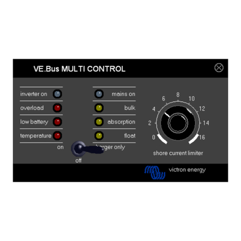
Victron energy VE.Bus User manual

Victron energy
Victron energy Color Control GX User manual

Victron energy
Victron energy Color Control GX User manual

Victron energy
Victron energy Skylla-i Control GX User manual

Victron energy
Victron energy VE.Net Blue Power Panel User manual

Victron energy
Victron energy Blue Power BMV-602 User manual

Victron energy
Victron energy CCGX User manual

Victron energy
Victron energy Digital Multi Control User manual