VICUT VR30 User manual

1/ 30
USER MANUAL
VICUT ROLL LABEL CUTTER VR30

2/ 30
Contents
I. Label Cutter Installation
II. Software “Label Studio” Installation
III. How to Creat First Label
IV. Touch Screen Panel Instruction
V. Calibration
VI. Roll Media Installation
VII. Blade Installation & Cutting Force Test
VIII. Basic Maintenance

3/ 30
I. Label Cutter Installation
Step 1: Preparation before unpacking
A. electric screw driver B. one computer
Step 2: Open the wooden package box by using the electric screw driver.
Step 3: Take Out the Roll Label cutter
Step 4: Take out the box of the spare parts, check if all the parts are completed.
Step 5: Put the machine on the table

4/ 30
Step 6: Connect the power line and turn on the machine
Step 7: Connect the machine with your computer by USB line.
After the connection is successful, the software will show whether the normal connection.

5/ 30
II. Software “Label Studio” Installation
Thanks for choosing our label cutter, please find the softwareCD from accessory box, install
it into a computer, then choose your appropriate exe. (Notice: One software could only be
installed in one computer.)
This program is dedicated to create precise cut layouts for batch label production.
This version of the software offers state of the art accuracy and scanning speed to boost
your production capabilities.
Also, the mark size has been reduced to only 5mm to allow maximum use of the printed
media.

6/ 30
Activating the Program
After installed the program, you will need to activate it before you are able to load in any
jobs. If you have not yet activated, you will see the following message when you try to load
in a job:
To Activate the program, click on the “Help” menu, and select “License Manager (Activate)”
to open the license manager screen. Click on “Activate” and follow the prompts.
Loading Artwork into Label Studio
Currently, Label Studio will load either PDF files, or Adobe Illustrator CS files.
The artwork should include the design elements to be printed, along with a special path
used to specify the cutting contours. The color of the cutting contours should be different
to any other colors used in the job, so that it can be uniquely selected.
Click on the “Load Job” icon and select the desired logo file you want to load.

7/ 30
After selecting the artwork, you will be presented with a series of options, allowing you to
change the physical size of the logo, apply cropping, and most importantly select the
cutting contours.
Selecting the Cutting Contours
On this example, you can see that there is a spot color in the artwork, called “CutContour”.
It does not need to be called this, and could be any color, as long as no other elements in
the design to use this color.

8/ 30
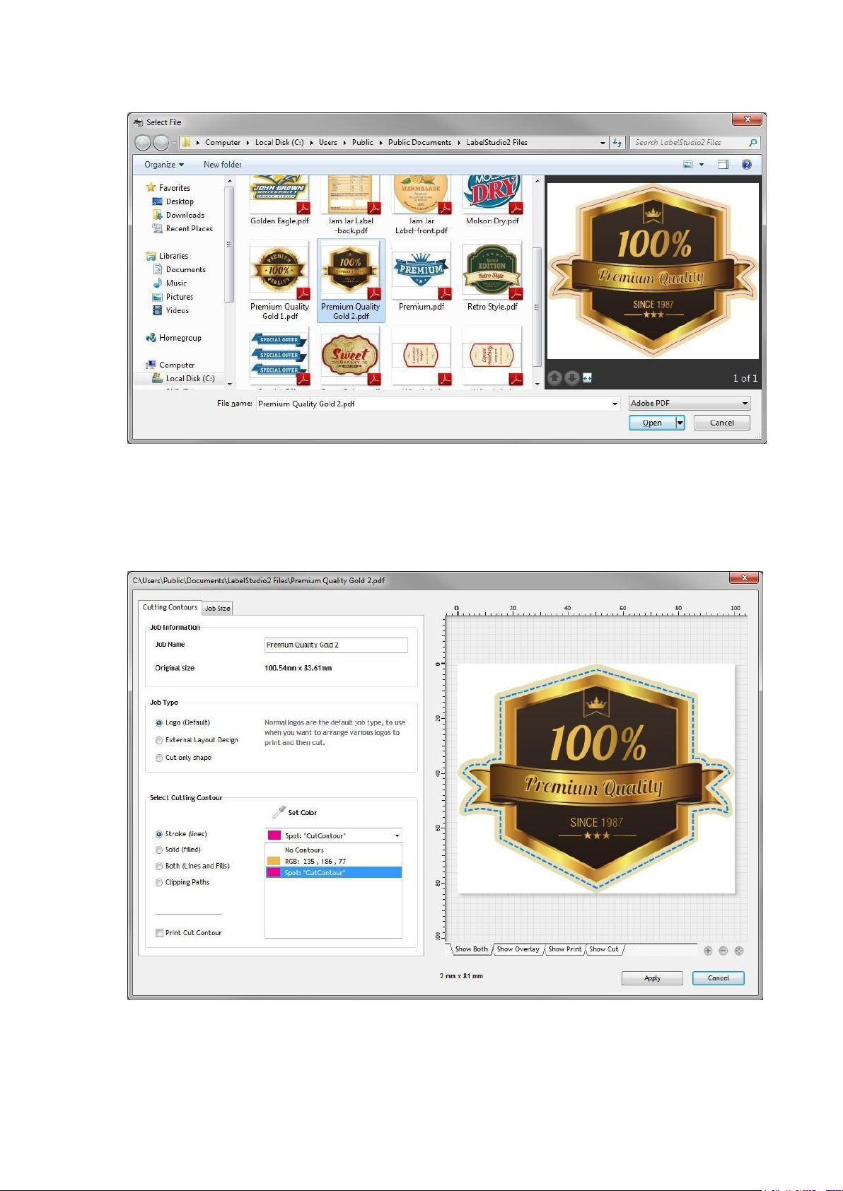
When you select the cutting color, you have the option to also allow this color to print, or by
default, the selected cutting color will not be printed. You can visually inspect the selected
cutting contours by changing the view mode to either “Show Overlay”, “Show Print” or
“Show Cut”.
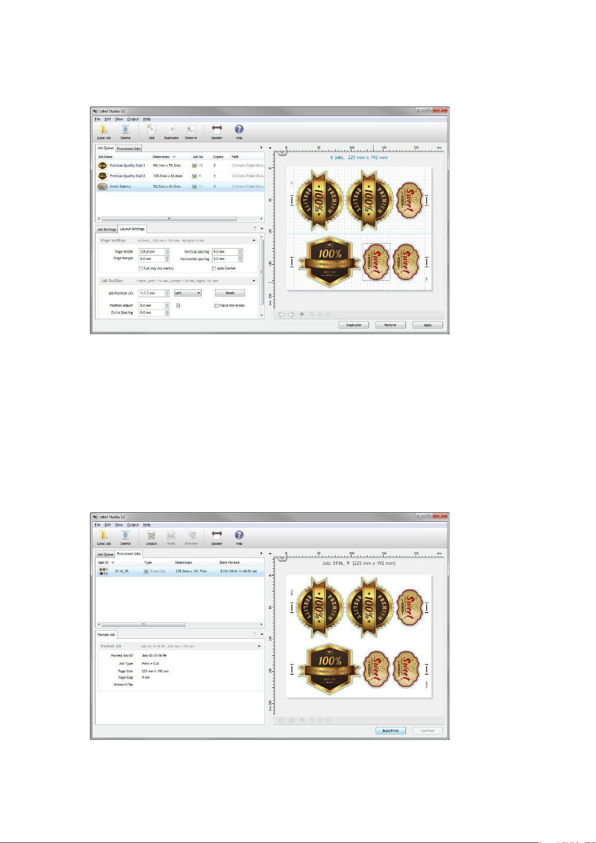
Creating a job layout
After you have loaded the required artwork jobs, you can now build a job layout to be print
and cut. The first thing you should do is specify the page options to match the size you
wish to print.
Paper Width: Total size of printed artwork. This should be slightly less than the maximum
printing size of your printer.
Edge Margin: How much gap to allow from the left and right edge of the paper, before
placing the alignment marks.
Vertical spacing: This setting is the amount of gap to add between each row of logos.
The page layout is designed so that when you print multiple copies of the layout, they
should be printed with no gaps between them (on the printer), as the exact gap spacing
required is already built into the page layout, using the vertical spacing setting. This allows
you to create a single layout that can be repeated as many times as you wish, joining
together seamlessly to fill your roll with the final print.
Horizontal spacing: The amount of gap to allow when positioning logos adjacently in
the horizontal direction.
Auto Center: When this setting is selected, the page is treated as a series of columns, so
if you had 2 logos on the same row, each would be cantered on either the left or right half
of the available layout. This setting is useful for multi row printing, where you want top and
bottom logos to be cantered to each other.
Adding Jobs to the Layout
With the selected jobs selected, click on “Add” to place the selected jobs into the current
layout.
The buttons at the bottom of the screen will change, depending upon the selection,

9/ 30
allowing you to duplicate the current job, add new ones, remove the selected jobs, or clear
the entire layout.
You can quickly add and remove jobs by simply double clicking on the item, either in the
list, or in the preview area.
To select all of the currently packed logos in the layout, click on the preview window,
away from any of the logos to unselect them all, and then double click to select them all.
To select multiple items in the current packed layout, hold down the shift key when you
click on them.
Applying the current layout
Once you are satisfied with the current layout, and wish to proceed, click on “Apply”.
This will remove the packed logos from the Job Queue, and create a new packed job in
the “Processed Jobs” list.
From here, you are able to generate the final artwork (PDF), print it, and also send the job

10 / 30
to be cut. You cannot cut the packed job, until you have created the final Artwork file.
You can control the quality of the final output, from the Output menu. By default the final
artwork is built using High quality mode (600dpi), but you can change it to 300dpi if you
wish.
There are also options to include the cut-lines, and exclude the image, but these options
are only for testing purposes, and should not normally be used when creating final
artwork.
Printing the artwork
After the final artwork has been built, clicking on the “Print” button will launch adobe
reader, displaying the printing dialog.
Here you should select the correct page size settings, and desired number of copies to
print. It is important that you print at 100% actual size, to ensure the cutting data
matches the size of the printed artwork.
Copying the Final Artwork to another folder/computer
If you wish to load the final artwork into a 3rd party program to handle the printing, or
copy it to another computer, you can quickly locate this file by selecting the “Inspect
Artwork file” from the “Output” menu.

11 / 30
The folder will be opened, with the artwork file selected.
Cutting the Packed Layout
After you have built the final artwork, you are now able to cut it out.
Select the file you wish to cut, and click on the “Cut” button to open the cutting spooler,
with that job selected.
Loading artwork into the cutter
You should position the laser in the middle of the right hand side mark, before you begin
cutting, and reset the cutter origin to 0,0.

12 / 30
Before you begin cutting any of your jobs, you will need to calibrate your cutter, and set the
tool options, such as blade offset, etc. These are covered later in this document.
The most important thing that you will need to do is calibrate the laser offset distance, so
the software knows the exact distance between the scanning laser, and the cutting blade,
so it can correct for this. If this setting is not calibrated correctly, the cutting paths will
appear shifted in a particular direction, and not match up with the printed artwork.
How to create a “Cut Only” Job
There may be situations where you do not need to print the artwork or prefer many
scanning to line it up, and simply want to cut out a group of shapes onto blank stock.
This is very easy to do, all you need is to select the “Cut Only (no marks)” in the Layout
settings when creating your layout.
When this setting is selected, you will notice that no scanning marks are drawn, and you
are not prompted to Build or Print the final artwork, and proceed directly to the cutting
stage.
Specifying the number of times to cut the Job
When cutting a job that involves scanning the marks, you do not need to worry about

13 / 30
setting the number of copies to cut, as soon as the last printed logo has been cut, the
software will not be able to detect any more marks, and will end the cutting process.
If you are cutting a “Cut Only” job however, this setting becomes quite important, so the
software knows when to stop cutting.
Click on the “Batch Process” option, and specify the number of copies you want to cut. In
the example above, 20 copies have been selected, and when you click “Cut Labels”, it will
only cut 20 copies, and then stop.
Cutting Wine Labels
One of the key features of Label Studio is the ability to create continuous wine label jobs,
where the spacing between each label is controlled precisely, to allow for automatic
application of the final cut- out result
Firstly, load in the artwork:
If the artwork has been designed with a lot of unwanted white space, you can trim this by
selecting the “Crop area” option when loading the artwork. You should be careful not to
accidentally crop any of the cutting paths.
By default, the “Use Cut area when packing” option is selected, which means the size of
the final cut-out label is what is used when calculating the spacing.

14 / 30
If you are printing both front and back labels, you can create a duel layout by adding both
jobs.
In addition, you can control the left/right positioning of both labels to ensure they are in
the position you need, relative to each other.
To control the position of each logo, you can use the “Job Position (x)” property.
If for example, you want both labels to be aligned to the right, you would select both of
them (using the shift key to multiple select), and then select “Right” as the positioning
option, and enter the desired value that both of the logos right edge ends up as.
Hint:
You can use the up and down cursor keys on the keyboard in any of the measurement
boxes in the program to increment / decrement the current value by 1mm, making quick
adjustments very easy.
How to handle small nested artwork
Because Label Studio is focused on repeat batch processing of simple row(s) of logos, you
will find that on each row, the logos are positioned one after the other.
If you have very small artwork and would like to create several vertical copies on the same
row, you should design a single logo in your design program, with several copies one on
top of the other, then load that logo in as a single logo.

15 / 30
(Example of a single logo used for vertical copies)
Once this logo is packed with other logos, you can see the result.
You can also inspect the printing or cutting elements on the preview window of the
program using the view mode dropdown.

16 / 30
How to design the cutting layout in a different program
If you have a very specific workflow, and need to handle the stepping up in another
program, you can achieve this by using the Template feature.
Firstly, design your artwork in another program, with the page size set to the printing width
of the artwork, and total height of the page (with any spacing between the logos included
in this size).
Make sure you allow about 15mm from each edge to provide enough space to fit the
marks.
After you have built your cutting color, you should save this page, with the cutting shapes
(all set to same cutting color), as a PDF.
Load this PDF into Label Studio, and select “External Template”. The job will go straight to
the Processed Jobs list.
When you build the final artwork file, a blank PDF will be created, containing a white box,
and the marks.
You should load this PDF file into your designing program, and align it to the bottom left
corner of your design and send it to the back.
This will provide the marks to your existing print layout that are synchronized with the
position of the cutting and printing components.
Cutting Settings
The software allows you to specify the settings you would like to use when cutting. The
most important of these is the blade offset (as well as Laser Offset).

17 / 30
In this screen, you can select the settings you wish to use. For items such as force and
speed, if you leave these settings unchecked, the current settings on the machine will be
used.
Loading the sample files
If you would like to practice with some of the included sample files, you will find them
located in the Public Documents\Label Studio2 files folder.
Size Restrictions
Because of the automated media takeup system, the machine is only physically able to cut
within a small area. It is recommended that you do not cut logos any higher than 120 –
130mm, to ensure you get the maximum accuracy that the machine is capable of.
Also, if you are cutting a very small logo, you will need to make multiple copies until the
layout is at least 60mm high, to allow enough space to include the marks.

18 / 30
III. How to Creat First Label
Step 1: Open your label studio software, import your label (the label includes image and
outline)
Step 2: Add label number you want
Step 3: Apply

19 / 30
Step 4: Build print
Step 5: Print the file use roll paper and make sure there is no gap between each. (such as
follow)

20 / 30
Step 6: Install paper on label cutter
Step 7: Move the laser on mark, then click “enter”
Table of contents
Other VICUT Cutter manuals
Popular Cutter manuals by other brands

ATIKA
ATIKA ST 250 Operating manual – safety instructions – spare parts

Woodtec
Woodtec XW053 instruction manual

Woods
Woods BATWING BW15.60 Operator's manual

Grizzly
Grizzly MINI SHEET METAL CUTTER INSTRUCTION SHEET... instruction sheet

Sumake
Sumake ST-660110T Original instructions

Land Pride
Land Pride SC2560 Operator's manual