VideoSys IDU-E User manual

1
T: +44 (0)1293 541 200
E: sales@Videosys.tv
W: www.Videosys.tv
The information contained in this document is the property of Videosys Broadcast Ltd. This document and the
information contained herein is provided for evaluation purposes only and is subject to change without notice.
Videosys Broadcast Ltd assumes no responsibility for errors that might appear in this document and gives no
representations or warranties as to the accuracy of the information contained herein, including but not limited to
the suitability and performances of the product or its intended application.
© Copyright Videosys Broadcast Limited 2018. All Rights Reserved. (Version 8.0)
IDU-E User Manual
Revision v8 - 18.09.20
Videosys Broadcast Ltd
Unit 1-2 Forest Barn Farm
Turners Hill Road
Turners Hill
West Sussex
RH10 4QH
UK

2
T: +44 (0)1293 541 200
E: sales@Videosys.tv
W: www.Videosys.tv
The information contained in this document is the property of Videosys Broadcast Ltd. This document and the
information contained herein is provided for evaluation purposes only and is subject to change without notice.
Videosys Broadcast Ltd assumes no responsibility for errors that might appear in this document and gives no
representations or warranties as to the accuracy of the information contained herein, including but not limited to
the suitability and performances of the product or its intended application.
© Copyright Videosys Broadcast Limited 2018. All Rights Reserved. (Version 8.0)
Contents
Camera Control Indoor Unit
3
Getting started
Introduction
Front and rear panels
Principal of Operation
4
Uni-directional
Bi-directional
Connecting Components
5
RCP, ODU, Tally, Power
Connector Wiring Diagrams
5
Data Out, Power Input Connector, Tally Input Connector, Generic Connector,
Sony Connector, Bi-directional Data Return Port
Navigating Menus
6, 7
Status Screens
Uni-directional Status Screen
Bi-directional Status Screen
Menu Structure
8, 9, 10
Camera Manufacturer, ODU, System, Camera Numbers, Network
Menu Item Descriptions
11, 12
Web Interface
13
Accessing the Web Interface
Navigating the Web Interface
14
Supported Cameras and Commands
15
Unit Updates
15
Backwards Compatibility
15
Physical Parameters
16
Dimensions, Electrical Parameters

3
T: +44 (0)1293 541 200
E: sales@Videosys.tv
W: www.Videosys.tv
The information contained in this document is the property of Videosys Broadcast Ltd. This document and the
information contained herein is provided for evaluation purposes only and is subject to change without notice.
Videosys Broadcast Ltd assumes no responsibility for errors that might appear in this document and gives no
representations or warranties as to the accuracy of the information contained herein, including but not limited to
the suitability and performances of the product or its intended application.
© Copyright Videosys Broadcast Limited 2018. All Rights Reserved. (Version 8.0)
Camera Control Indoor Unit
Introduction
The Videosys camera control system allows the user to replace the cables between the Remote-Control Panels,
Camera Control Units and Cameras. The Videosys IDU connects directly to existing control panels and in
combination with other components from the Videosys camera control range provides a robust broadcast
quality solution.
The Videosys camera control solution consists of three distinct components; an ‘IDU’ (Indoor Unit), ‘ODU’
(Outdoor Unit) and an ‘RX’ (Receiver). Multiples of these components can be used to best fit the operator’s
requirements, for example multiple IDU’s can be connected to allow for many camera control paths over one
ODU. Multiple ODU’s can be used to increase RF coverage, and each camera to be controlled requires an RX.
From this point on to avoid ambiguity and keep things concise, the terms IDU, ODU, RCP and RX will be used.
We hope that you will find the necessary information within this manual and our specific quick setup guides, if
however, you require additional support please don’t hesitate to contact your local distributor.
1OLED Display 7 Red Tally Input Connector (8 pin DIN)
2Cancel Button 8 Green Tally Input Connector (8 pin DIN)
3Enter Button 9 Bi-directional Data Return Connector (D9)
4 Navigation 10 Ethernet Connector (RJ45)
5 Power Input Connector (4 Pin XLR, Male) 11 Data Output Connector (3 Pin XLR, Female)
6 Legacy Camera Connectors (‘Generic’ or ‘Sony’)
3
4

4
T: +44 (0)1293 541 200
E: sales@Videosys.tv
W: www.Videosys.tv
The information contained in this document is the property of Videosys Broadcast Ltd. This document and the
information contained herein is provided for evaluation purposes only and is subject to change without notice.
Videosys Broadcast Ltd assumes no responsibility for errors that might appear in this document and gives no
representations or warranties as to the accuracy of the information contained herein, including but not limited to
the suitability and performances of the product or its intended application.
© Copyright Videosys Broadcast Limited 2018. All Rights Reserved. (Version 8.0)
Principal of Operation
The Videosys camera control system can be configured to operate using one of two fundamentally different
architectures, descriptions of the architectures and their relative advantages and drawbacks are as follows:
Uni-directional
In this mode the IDU acts as a ‘Virtual Camera’ and
talks to the RCP via its native protocol. Changes to this
Virtual Camera are then encoded into our low latency
protocol.
Encoded data is routed from the IDU to the ODU
where it is transmitted. Data is then received via the
RX. Within the RX a ‘Virtual Panel’ is updated with the
received information, the ‘Virtual Panel’ then
communicates with the camera using its native
protocol.
Bi-directional
In this mode an RCP natively communicates to the IDU.
Data is then conditioned and forwarded on to the ODU,
where it is then transmitted. An RX then receives
transmitted data and communicates with the
manufacturer’s camera. Return data is fed from the RX
via a return path back to the IDU. The return path is
typically provided via the data path on many COFDM
video transmitters.
•This approach allows high performance in an extremely
poor RF environment as data loss will not cause link
failure.
•Uni-directional operation boasts simple setup, as only
one data path needs to be configured.
•Due to the use of an intermediate protocol, Uni-
directional operation allows operators to mix and
match different manufacturers cameras and control
panels.
•As each command has to be specifically implemented
and handled, not all of the features available on
manufacturers cameras and control panels will be
available when used with a Uni-directional control link.
Fig 1. A simple Uni-directional camera control setup
•All of the features that would be available via a cabled
setup are available via our Bi-directional setup.
•Due to the bandwidth restrictions of the RF path, RCP
wake-up times might be slightly longer than in a wired
or Uni-directional set up.
•Due to the reliance on two communication paths,
wireless control is not as robust as with Uni-
directional operation.

5
T: +44 (0)1293 541 200
E: sales@Videosys.tv
W: www.Videosys.tv
The information contained in this document is the property of Videosys Broadcast Ltd. This document and the
information contained herein is provided for evaluation purposes only and is subject to change without notice.
Videosys Broadcast Ltd assumes no responsibility for errors that might appear in this document and gives no
representations or warranties as to the accuracy of the information contained herein, including but not limited to
the suitability and performances of the product or its intended application.
© Copyright Videosys Broadcast Limited 2018. All Rights Reserved. (Version 8.0)
Connecting Components
The first step is to connect the components of your camera control system.
RCP
This can be connected via an Ethernet network using
the RJ45 connector, or via the appropriate cable to the
numbered legacy connectors on the back of the unit. A
range of pre- made cables and cable wiring diagrams
are available on our website or via contacting your local
sales representative.
ODU
There are two options for connecting to an ODU, either
via the Data Out Connector or using the RJ45 and via an
Ethernet Network.
Connector Wiring Diagrams
The following diagrams are from the point of view of the rear panel of the IDU facing the user.
Tally
The IDU can be connected into an existing tally
system via the Tally Input Connector, this will
respond to contact closure, open collector input
and TTL logic levels (inverted).
Power
Connect 12V DC to the Power input XLR
connector. When powered the unit will display a
boot screen and then present the user with a
status screen.

6
T: +44 (0)1293 541 200
E: sales@Videosys.tv
W: www.Videosys.tv
The information contained in this document is the property of Videosys Broadcast Ltd. This document and the
information contained herein is provided for evaluation purposes only and is subject to change without notice.
Videosys Broadcast Ltd assumes no responsibility for errors that might appear in this document and gives no
representations or warranties as to the accuracy of the information contained herein, including but not limited to
the suitability and performances of the product or its intended application.
© Copyright Videosys Broadcast Limited 2018. All Rights Reserved. (Version 8.0)
Navigating Menus
The Up, Down, Left, Right, Enter and Cancel buttons can be used to navigate through the menus. Menus are
organised into lists; these can be scrolled through with the Up and Down buttons. To enter the selected submenu
or option press the Enter button. Cancel will return you to previous menu, potentially discarding any unsaved
changes made within the current menu. The Left and Right buttons are predominantly used to select which
character is being edited in settings such as IP address or Frequency.
Status Screens
The first screen that will be displayed to the user is the status screen, depending on the mode that the unit is set
to this will either be the Uni-directional control status screen (fig 1) or the Bi-directional control status screen (fig
2).
Fig 1. Uni-directional operation mode status screen Fig 2. Bi-directional operation mode status screen
Uni-directional Status Screen
The Uni-directional control status screen has numbered rows that represent the RCPs that the IDU can connect
to. There can be a maximum of four RCP’s per IDU, although the unit may display less depending on licencing.
Each RCP can have two states; Connected or Disconnected.
When an IDU and panel are successfully communicating ‘Connected’ is displayed. In Uni-directional mode the
IDU does not know, and therefore cannot tell the user anything about the transmit, receive or RX to Camera
connection status.
Bi-directional Status Screen
Bi-Directional Control (BiDi) can be broken down into four main data paths, each of which must be configured
for correct operation. The status of the BiDi connections are under state machine control, generating 5 pages of
diagnostic information to assist in BiDi configuration, these are navigated using the UP/DOWN arrow buttons.
1. Home Status
2. Return Link Status
3. Forward Link Status
4. Panel Connection Status
5. Camera Connection Status

7
T: +44 (0)1293 541 200
E: sales@Videosys.tv
W: www.Videosys.tv
The information contained in this document is the property of Videosys Broadcast Ltd. This document and the
information contained herein is provided for evaluation purposes only and is subject to change without notice.
Videosys Broadcast Ltd assumes no responsibility for errors that might appear in this document and gives no
representations or warranties as to the accuracy of the information contained herein, including but not limited to
the suitability and performances of the product or its intended application.
© Copyright Videosys Broadcast Limited 2018. All Rights Reserved. (Version 8.0)
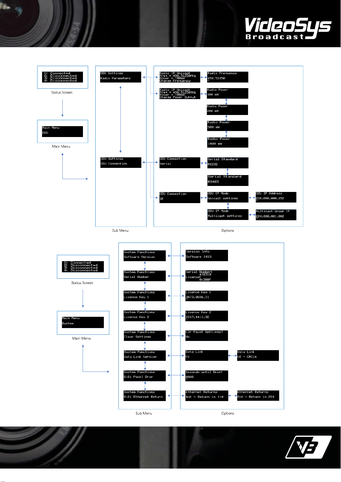
Each screen has a number of possible states, reported as follows:
Home Status
•Not Ready - At least one of the four data paths are not currently connected or configured correctly.
•Sync - All four data paths are connected, but Panel and Camera are still initialising.
•Active - The system is initialised and operational.
Return Link Status
•Return Not OK - No valid data is being received on the return port. Check connections and settings from RX
all the way through to the IDU.
•Return ID?? - Valid data is coming through however the Camera ID being returned from the RX does not
match the Channel number on the IDU.
•Return OK - The IDU is receiving good return data from the RX.
Forward Link Status
•Forward?? - The state of the forward link cannot be determined as the return path is not correct.
•Forward Not OK - Forward link is known to not be OK. Check connections from the IDU to the ODU and
camera control radio frequencies.
•Forward OK - Both Return and Forward links are both OK. The Bi-Directional link is established.
Panel Connection Status
•Panel?? - Status of the connection to the panel cannot be determined. This could be due to the “BiDi Panel
Drop” option being enabled.
•Panel Not Ok - Connection to the panel is not established.
•Panel Sync - Connection to the panel is established, but not yet initialised.
•Panel OK - Connection is OK and ready to be used by an operator.
Camera Connection Status
•Camera?? - The status of the connection to the camera cannot be determined. This is likely to be due to the
Bi-Directional link not being established.
•Camera Type? - RX has an invalid camera type selected.
•Camera Not OK - Connection between the RX and the camera is not established.
•Camera Sync - Connection to the camera is established, but not yet initialised.
•Camera OK - Connection is OK and ready to be used by an operator.
For a full description of BiDi setup please consult the BiDi Quick Start guide available on our website
www.Videosys.tv.

8
T: +44 (0)1293 541 200
E: sales@Videosys.tv
W: www.Videosys.tv
The information contained in this document is the property of Videosys Broadcast Ltd. This document and the
information contained herein is provided for evaluation purposes only and is subject to change without notice.
Videosys Broadcast Ltd assumes no responsibility for errors that might appear in this document and gives no
representations or warranties as to the accuracy of the information contained herein, including but not limited to
the suitability and performances of the product or its intended application.
© Copyright Videosys Broadcast Limited 2018. All Rights Reserved. (Version 8.0)
Menu Structure
Pressing enter will move the user from the status screen
to the main menu, this main menu allows the user to
navigate to a category, these are as follows;
‘Camera Manufacturer’ –Allows the user to select a
camera manufacturer, depending on the camera it
might also guide the user through menus asking which
camera models are being used. There are then options
for Serial, Ethernet, Bi-directional or Uni-directional.
‘Camera Numbers’ – Sets which camera numbers are
matched to which channels, these camera numbers are
used to specify which receiver is listening for that data.
‘Network’ – Contains submenus for the IDUs IP
settings, Channel IP settings and Camera Network
settings. Channel settings are the IP addresses for
panels to connect to via IP. Camera Network
settings has manufacturer specific settings such as
specific ports to use for connection.
‘ODU’ – Communicates with an ODU, displaying and
allowing the user to modify the radio frequency and
transmit power.
‘System’ – Contains a range of settings relating to
the IDU itself, Serial numbers, Licence options, Data
output, Paint settings reset and version information.
CAMERA MANUFACTURER

9
T: +44 (0)1293 541 200
E: sales@Videosys.tv
W: www.Videosys.tv
The information contained in this document is the property of Videosys Broadcast Ltd. This document and the
information contained herein is provided for evaluation purposes only and is subject to change without notice.
Videosys Broadcast Ltd assumes no responsibility for errors that might appear in this document and gives no
representations or warranties as to the accuracy of the information contained herein, including but not limited to
the suitability and performances of the product or its intended application.
© Copyright Videosys Broadcast Limited 2018. All Rights Reserved. (Version 8.0)
SYSTEM
ODU

10
T: +44 (0)1293 541 200
E: sales@Videosys.tv
W: www.Videosys.tv
The information contained in this document is the property of Videosys Broadcast Ltd. This document and the
information contained herein is provided for evaluation purposes only and is subject to change without notice.
Videosys Broadcast Ltd assumes no responsibility for errors that might appear in this document and gives no
representations or warranties as to the accuracy of the information contained herein, including but not limited to
the suitability and performances of the product or its intended application.
© Copyright Videosys Broadcast Limited 2018. All Rights Reserved. (Version 8.0)
NETWORK
CAMERA NUMBERS

11
T: +44 (0)1293 541 200
E: sales@Videosys.tv
W: www.Videosys.tv
The information contained in this document is the property of Videosys Broadcast Ltd. This document and the
information contained herein is provided for evaluation purposes only and is subject to change without notice.
Videosys Broadcast Ltd assumes no responsibility for errors that might appear in this document and gives no
representations or warranties as to the accuracy of the information contained herein, including but not limited to
the suitability and performances of the product or its intended application.
© Copyright Videosys Broadcast Limited 2018. All Rights Reserved. (Version 8.0)
Menu Item Descriptions
Main Status - Shows the connection status of the RCP to the IDU either connected or Disconnected, the camera
number and if Red or Green tally is set for each port indicated by an R and a G.
Main Menu - This is entered from the Status screen by hitting the ENTER button. From here the user can access
the Camera Manufacturer, ODU, System, Network and Camera Numbers menus. Note: some menu options
may be license option specific.
Camera Manufacturer
From here the camera manufacturer type, subject to license option can be selected. The menu structure will
take the user through a logical set of options for the connection type, serial or IP and the mode of operation Uni
or Bidirectional control.
ODU
From the ODU menu the ODU and operation features can be accessed.
Radio Parameters - Shows the status of the radio in the ODU. The transmit frequency and the RF output power
can be set. This will also display the current connection mode, serial or IP.
ODU Connection - Menu allows the selection of serial (RS232 or RS485) or IP (Unicast or Multicast).
System
Software version - Displays the current version of software installed.
Serial Number - Shows the unit serial number and installed license options.
License Key 1 and 2 - License Keys are issued as a two-part numbered code, key 1 and key 2 are entered in the
appropriate window.
Clear Settings - Resets the RCP/OCP parameters back to ‘centre’ positions– all zeros on most panels. This is
used for Uni-directional mode only.
Data Link Version - We have two modes for data transmission, V1 and V2. Note V1 is obsolete but can be
selected to maintain compatibility with older camera data receivers. NOTE: V1 is not compatible with newer RX-
E units, you must use V2.
BiDi Panel Drop - In Bi-directional mode some manufacturers panels will drop the connection as soon as the link
is interrupted. This could be caused by interference or a simple battery change. The user can choose how long
the panel will maintain the connection in seconds before it will be dropped. Default 0000s means infinite –the
panel will never drop connection.
BiDi Ethernet Return - Allows the user to decide which ports the reverse data will input to the IDU, 4 channel
operation the return ports are 1-4 or 2 channel operation the return ports are 2 and 4.

12
T: +44 (0)1293 541 200
E: sales@Videosys.tv
W: www.Videosys.tv
The information contained in this document is the property of Videosys Broadcast Ltd. This document and the
information contained herein is provided for evaluation purposes only and is subject to change without notice.
Videosys Broadcast Ltd assumes no responsibility for errors that might appear in this document and gives no
representations or warranties as to the accuracy of the information contained herein, including but not limited to
the suitability and performances of the product or its intended application.
© Copyright Videosys Broadcast Limited 2018. All Rights Reserved. (Version 8.0)
Network
IDU network connection parameters. The default IP range for the unit is 192.168.1.xxx. NOTE - IP set up is far
easier using the web browser.
Channel IP Settings - Static IP addresses for each connection port 1 to 4. Plus, Gateway and Netmask.
Camera Network - Sony MSU address and Panasonic RCP port addresses are entered here.
ODU-E Network - Settings for the ODU connections. These are duplicate meus as seen under the ODU sub-
menus.
IDU IP Settings - Units base settings.
IP Address –The main IP address for the unit and is used to access the web browser. The default IP address id
192.168.1.200.
Netmask, Gateway - Unit netmask default setting 255.255.255.0 default gateway 192.168.1.254.
Cascade Target IP - Used to cascade IDUs together allowing more cameras to be controlled over a single ODU.
The target is the main unit IP address of the next IDU in the cascade.
NOTE - This also used to be used for the target address of the ODU when using the ODU in IP connection mode.
This has been superseded, the Cascade Target must not be used to target the ODU, the ODU now has its own IP
address entry menu.
Camera Numbers
The production camera numbers can be set for each port 1 through to 4. This becomes important when using
IP panel connections as some manufacturers use the camera number to identify the panel to camera data
connection.

13
T: +44 (0)1293 541 200
E: sales@Videosys.tv
W: www.Videosys.tv
The information contained in this document is the property of Videosys Broadcast Ltd. This document and the
information contained herein is provided for evaluation purposes only and is subject to change without notice.
Videosys Broadcast Ltd assumes no responsibility for errors that might appear in this document and gives no
representations or warranties as to the accuracy of the information contained herein, including but not limited to
the suitability and performances of the product or its intended application.
© Copyright Videosys Broadcast Limited 2018. All Rights Reserved. (Version 8.0)
Web Interface
The IDU has a built-in webserver and serves a range of
useful control pages, if the user has a device with a web
browser on the same network, they can use this interface
to quickly change settings, perform updates and utilise
the virtual RCP feature.
Fig 3. The IDUs Network Configuration Webpage
Fig 4. The IDUs Maintenance Webpage
Accessing the Web Interface
To Access the Web interface, firstly power up the IDU
and connect a PC or laptop up to the same IP network as
the IDU. Find the IP address of the IDU (this can be
found via Network -> IDU settings -> IDU IP Address) and
enter this into the web browser, this will take the user
to the IDUs configuration web page.
Videosys default IP address for the IDU is 192.168.1.200.

14
T: +44 (0)1293 541 200
E: sales@Videosys.tv
W: www.Videosys.tv
The information contained in this document is the property of Videosys Broadcast Ltd. This document and the
information contained herein is provided for evaluation purposes only and is subject to change without notice.
Videosys Broadcast Ltd assumes no responsibility for errors that might appear in this document and gives no
representations or warranties as to the accuracy of the information contained herein, including but not limited to
the suitability and performances of the product or its intended application.
© Copyright Videosys Broadcast Limited 2018. All Rights Reserved. (Version 8.0)
Navigating the Web Interface
Once the webpage has loaded (see ‘Accessing the
Web Interface’) the ‘Network’ Page is then visible
(fig 3), from this page the unit can be easily and
quickly configured as part of an IP network. There is
also a ‘Maintenance’ page (fig 4), giving
device information and allowing for updates (these
can be found on our website).
Fig 5. The IDUs Front Panel Webpage
Fig 6. The IDUs Remote Panel Webpage
The ‘Front Panel’ page (fig 5) literally mirrors the
information presented on the IDUs front panel and
allows for all of the same functionality as the units’
physical front panel. There is also a ‘Remote Panel’
page (fig 6); this is a ‘Virtual RCP’ and allows for all of
the settings that we support in Uni-Directional mode to
be controlled directly from the browser.

15
T: +44 (0)1293 541 200
E: sales@Videosys.tv
W: www.Videosys.tv
The information contained in this document is the property of Videosys Broadcast Ltd. This document and the
information contained herein is provided for evaluation purposes only and is subject to change without notice.
Videosys Broadcast Ltd assumes no responsibility for errors that might appear in this document and gives no
representations or warranties as to the accuracy of the information contained herein, including but not limited to
the suitability and performances of the product or its intended application.
© Copyright Videosys Broadcast Limited 2018. All Rights Reserved. (Version 8.0)
Supported Cameras
and Commands
The vast majority of commands that would be used
day to day are available via Uni-directional control,
and the full command set should be available via Bi-
directional control.
For a full list of supported cameras and commands
please see the software release notes provided with
our software updates, software updates are regularly
released and we hope to keep our range of supported
cameras expanding. If you do not find the information
required or would like assistance, please contact us.
Unit Updates
To update an IDU, a new firmware image is required,
these are available on our website. Please check the
release notes bundled with the firmware images
carefully, they will explain precisely what changes
have been made. The next step is to access the
webpage (see ‘Accessing the Web Interface’). On the
‘Maintenance’ page (fig 5), there is a software update
section, this section can be used to select and upload
the file required. During the update the IDU will show
it is restarting and then that is the update completed.
Further questions regarding which firmware images
should be used or for any additional support please
contact your local distributer.
Backwards
Compatibility
We have multiple generations of hardware, which
due to our commitment to backwards compatibility
can, in the vast majority of cases, still be used to
build a high-performance camera control system.
For integrating new components into a previous
generation system, some of our latest features
might not be available. Please check our software
release notes for the version that you
are running or contact our sales department for
more information.

16
T: +44 (0)1293 541 200
E: sales@Videosys.tv
W: www.Videosys.tv
The information contained in this document is the property of Videosys Broadcast Ltd. This document and the
information contained herein is provided for evaluation purposes only and is subject to change without notice.
Videosys Broadcast Ltd assumes no responsibility for errors that might appear in this document and gives no
representations or warranties as to the accuracy of the information contained herein, including but not limited to
the suitability and performances of the product or its intended application.
© Copyright Videosys Broadcast Limited 2018. All Rights Reserved. (Version 8.0)
Physical Parameters
Dimensions
Width: 220mm excluding rack ears 262mm with rack ears.
Height: 44mm
Length: 349mm
Weight: 1.15kg
Weather proofing: None
Temperature Range: 0-50 °C
Sound Output: 0db - Fanless
Electrical Parameters
Operating Voltage: 9-18V
Current Consumption: > 1A
Be aware that RCPs can be powered up via the IDU,
this will increase the current draw significantly.
Table of contents
Other VideoSys Control Unit manuals
Popular Control Unit manuals by other brands

Dungs
Dungs FRM 100025 instruction manual

Hosiden
Hosiden HRM1017 user manual

Flowserve GESTRA
Flowserve GESTRA GAV 54F Installation & operating instructions

Johnson Controls
Johnson Controls TYCO DPV-1 Technical data

Allen-Bradley
Allen-Bradley 1794-IE8 Series B user manual

Keysight Technologies
Keysight Technologies 81618A user guide

O.S. engine
O.S. engine EC-11 instruction manual

ATI Technologies
ATI Technologies VB12-M Installation and operation manual

Supermicro
Supermicro MicroBlade MBI-6218G-T41X user manual

Vortice
Vortice CREN Instruction booklet

Texas Instruments
Texas Instruments SimpleLink BoosterPack BOOSTXL-CC3120MOD manual

Multiplex
Multiplex HFMx V2 M-LINK operating instructions