4
zConrm set address/function with .
The device applies the setting and returns to
the previous menu entry. .
Display saved error codes
Device errors of the call push-button module that
occur during operation are stored in the the error
memory of the device for diagnosis.
zSelect menu entry with button / and
conrm with
If no error code exists is displayed for 2
seconds and afterwards .
If error codes are saved ashes followed by
the module address and the error code.
zPress button / , to call up further error
codes if necessary.
zPress button to return to menu entry .
Error
code
Error cause Counter actions
Communication error
between device and
call push-button mod-
ule. Once the error
has occurred 3 times,
the system is reset
automatically and the
error code is gener-
ated.
If the error per-
sists, the call
push-button
module must be
replaced.
sticking call button Check call
push-button
module If there
is a defect, re-
place and ad-
dress.
Writing of the call
push-button address
in the call push-button
module fails.
If the error per-
sists, the call
push-button
module must be
replaced and
re-addressed.
Table 2: Error codes and counter actions
The memory should only be deleted once 5
error codes have been stored, so that new error
codes can be saved.
Identical error codes are only saved once.
Dismantle call push-button module cover
For cleaning or replacement, the call push-button
module cover can be dismantled from the front.
zLever up the interlocking cover strips (13) at
the top and bottom using the screwdriver and
remove (Figure 11).
(13)
Figure 11: Removing the cover strips
(13) Cover stripes
zLift the call push-button module upper part
in the bottom lever opening slightly with the
screwdriver and guide it forwards (12).
P
P
(14)
Figure 12: Dismantling the call push-button module
cover
(14) Call push-button module cover
Defective covers can only be replaced by
covers with the same number of push-buttons.
zRemove the module to be replaced and install
the new module in reverse order.
Exchange module/insert
Door station is open and activated.
zPull off connection terminal block (11) on the
device.
zRemove the connection cables’ connectors on
the module to be exchanged.
zRemove screws/nuts from mechanic module
mountings and remove module mounting (see
already available installation instruction, e.g.
door station, frame, etc.).
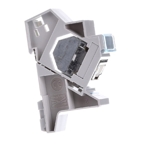
zTo remove the call push-button module,
unlatch the side retaining brackets (15) of the
module mounting by carefully lifting up with a
screwdriver (Figure 13).
(15)
Figure 13: Unlatching module
(15) Retaining brackets module mounting
The module detaches itself from the anchoring.
zRemove the module to be replaced and install
the new module in reverse order.
Re-addressing of the device is required to
operate the door station.
P
P
Appendix
Technical data
Operating voltage 22 ... 24 V=
Current consumption audio Stand by 5 mA
Current consumption audio device operation 110 mA
Current name plate lighting
per call push-button module 45 mA
Menu
setting
Backlighting On Backlighting Off
0 Permanent Off
1
2
3
4
5
6
7
8
9
≈ 750 lx
.
.
.
.
.
.
.
≈ 60 lx
≈ 1600 lx
.
.
.
.
.
.
.
≈ 110 lx
10 Permanent On
Table 3: Brightness of LED backlighting
Door release contact T/T potential-free max. 24 V/1 A
Door release unlocking time 1 ... 10 s
Degree of protection IP 44
Degree of protection (degree of impact resistance) IK07
Relative humidity 0 ... 65% (no condensation)
Operating temperature -20°C … +55°C
Storage/transport temperature -30°C … +80°C
Connecting terminals
for conductor diameter 0.5 ... 0.8 mm
Installation height (middle of the loudspeaker) ca. 1.5 m
Dimensions:
Call push-button button small 75.8 x 14.5 mm
Name plate small 72.1 x 12 mm
Width of name plate insert small max. 0.5 mm
Call push-button button medium 75.8 x 3.6 mm
Name plate medium 72.1 x 30.1 mm
Width of name plate insert medium max. 0.5 mm
Call push-button button large 75.8 x 75.8 mm
Name plate large 72.1 x 66.3 mm
Width of name plate insert large max. 0.3 mm
6LE002642A Ind. A12.2017
