Choosing the tank profile
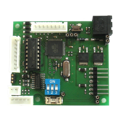
The driving and function setup is determined y the position of the DIP switches. The Tank Module ECO offers seven fixed and one user
defined profile
German, WW2, plastic gear oxes US, WW2, metal gear oxes
German, WW2, metal gear oxes T-34
German, WW2, 3:1 reduced gear ox easy-to-drive tank
user defined
US, WW2, plastic gear oxes setup used y the ThinkTank Configurator
and PC Configurator
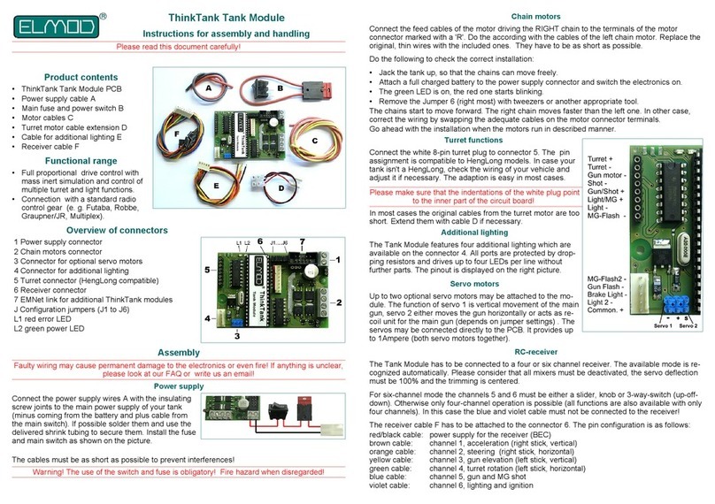
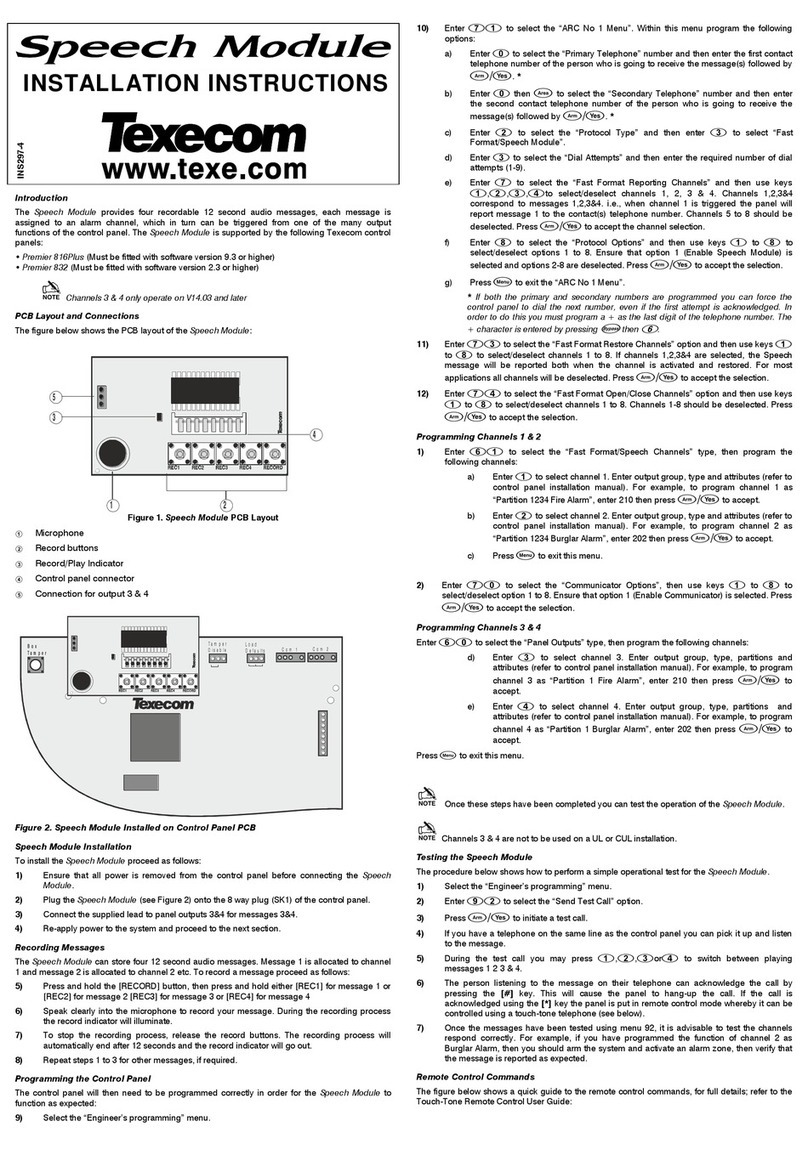
Status LED
The on oard LED shows the current status of the module
on Tank Module is in operational state *no connection to the sender or the transmission path etween
sender and receiver is distur ed. Please check the wiring and the
proper function of the RC radio and receiver. If necessary check
the opera ility of the RC equipment with a servo.
**undervoltage on the CPU detected. Switch the power off for 10
seconds. If the error remains, assure that the PC Configurator
USB dongle is disconnected and retry.
Short going out Stick movement detected
Fast linking No valid signal from receiver*
Slow linking Faulty communication with another module
Dou le linking Faulty CPU power supply**
RC receiver
This Tank Module may e connected with four to eight channel receiver. The currently active mode of operation is recognized automatically.
Please consider that the radio must e setup correctly (all mixers must e deactivated, the servo deflection must e 100% and the trimming is
centered)
If the channels five to eight are used, they must e equipped either as a slider, kno or 3-way-switch (up-off-down). Otherwise only four-
channel operation is possi le (although mostly all functions are also availa le with only four channels). The wires of unused channels may
not e connected to the receiver.
The receiver ca le has to e attached to the receiver connector on the Tank Module. The wire color pin assignment is as follows:
The Tank Module electronics provides the power supply for the receiver (BEC, sta ilized 5V DC) via the red/ lack wires which are part of the
proportional ca le set.
Ch. Control 4-channel mode 5-channel mode 6-channel mode
1Right stick Acceleration Acceleration Acceleration
2Steering Steering Steering
3Left stick Turret, weapon and special functions Turret and weapon control Turret control
4
5Kno or slider Not connected Ignition and light Ignition and light
6Kno or slider Not connected Not connected Weapon control
The channels 7 and 8 may e optionally used to control the user defined sounds of the sound module ThinkTank Blaster.
Ch. Control Function
73-way-switch User defined sounds: Sample 1 and 2
83-way-switch User defined sounds: Sample 3 and 4
Depending on the receiver it may e necessary to adjust the channel order or swap its movement direction. Check the manual of your rc gear
for details.
Turret, eapon and special functions using 4-channel mode
This mode is active if the lue wire of the receiver ca le isn't attached to the receiver. The turret, weapon and special functions are controlled
solely y the left stick of the radio.
Left stick (channels 3 and 4)
éLift the main gun (half deflection) éShot (maximum deflection)
êLower the main gun (half deflection) êMachine gun (maximum deflection)
èRotate turret right Auxiliary MG
çRotate turret left Main light on/off
Ignition (requires ThinkTank Blaster) Aux light on off
