manuals.online logo
Brands
  1. Home
  2. •
  3. Brands
  4. •
  5. Videx
  6. •
  7. Intercom System
  8. •
  9. Videx Art.8835 User manual

Videx Art.8835 User manual

8835 1.0 05/10/07 13/01/11 -Pag.1/4
CC1P1P2NOCOD1D
NC+CCP
Made in Italy
8835-0Aluminium
8835-1Stainless steel
8835-2
Balance
Art.8835 Art.8835-0 Art.8835-1 Art.8835-2
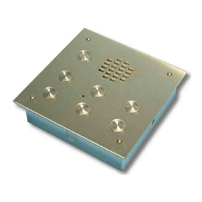
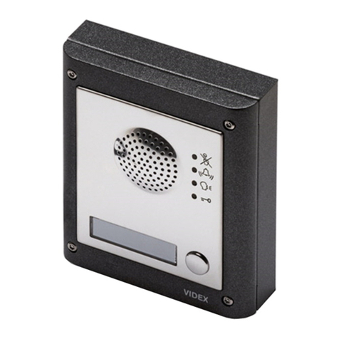
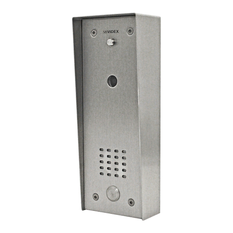
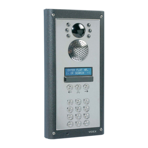
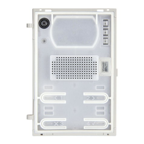
Are used for “1+1” audio door entry systems or in combination with camera mod-
ule Art.8830 for “4+1” video door entry systems using balanced video signal. The
back of the speaker unit module is made from plastic and houses the module
circuitry. The top is a plastic cover covered by a front plate (available in different
finishes) that has 0, 1 or 2 call buttons depending on the speaker unit model
(8835-0, 8835-1, 8835-2).
•The module circuitry includes:
•The voltage rectifier and stabilizer circuits;
•2 modulated tone generator for main and local call;
•The transmitting amplifier with condenser microphone;
•The receiving amplifier and volume control;
•The audio balance circuit with the relevant “BALANCE” control;
•The voltage reader circuit: depending on the voltages changes on terminal “D”
caused by operation the circuit enable or disable speech line and door open;
•1 LED to illuminate the name plate (except the 4835-0 model).
•The lock release relay to enable the electric lock.
Balance trimmer and loudspeaker volume trimmer are on available on the back
of the module.
DCommon speech
D1 Common speech diode for extension panels
Power input 13Vac
CO Door open relay – Common contact
NO Door open relay – Normally open contact
Power input 0V
P2 Push button 2 output (used only in -2 version)
P1 Push button 1 output (used only in -1 and -2)
C1 Push button common (P1, P2)
CElectronic call tone output
CP Call tone output for local call (or floor call)
+C Timed output to control video power supply Art.893N1
NC Door open relay – Normally closed contact
Sono impiegati nei sistemi citofonici “1+1” o nei sistemi videocitofonici “4+1”
con segnale video bilanciato in abbinamento al modulo telecamera Art.8830. Il
modulo si compone di una base posteriore in plastica che ospita la circuiteria,
un coperchio superiore in plastica che permette di alloggiare pulsanti e l’altopar-
lante e di una placca frontale metallica (disponibile in diverse finiture) che può
presentare 0, 1 o 2 pulsanti di chiamata in base al modello di portiere (8835-0,
8835-1 o 8835-2).
L’elettronica del modulo comprende:
•Il circuito di rettifica e stabilizzazione della tensione;
•2 circuiti generatori di nota modulata (per chiamata principale e locale);
•L’amplificatore di trasmissione con microfono a condensatore;
•L’amplificatore di ricezione con altoparlante da 0,5W e regolazione del volume;
•Il circuito di bilanciamento della fonia con relativa regolazione “BALANCE”;
•Il circuito di lettura della tensione D: in base alle variazioni provocate dalle
operazioni svolte durante il funzionamento il circuito abilita o disabilita la fonia
ed il relé apri-porta;
•1 LED d’illuminazione cartellini (escluso 4835-0);
•Il relé di apertura porta.
I trimmer di regolazione del volume altoparlante e balance sono accessibili dalla
parte posteriore del modulo.
DComune fonia
D1 Comune diodi per pulsanti di chiamata aggiuntivi
Ingresso d’alimentazione 13Vac
CO Relè apri-porta - contatto comune
NO Relè apri-porta - contatto normalmente aperto
Ingresso d’alimentazione 0V
P2 Uscita pulsante 2 (utilizzato solo nella versione -2)
P1 Uscita pulsante 1 (utilizzato nelle versione -2 e -1)
C1 Comune pulsanti (P1, P2)
CUscita nota elettronica
CP Uscita nota elettronica per chiamata locale (o di piano)
+C Uscita temporizzata per attivazione alimentatore video 893N1
NC Relè apri-porta - contatto normalmente chiuso
Art.8835
Installation Instructions
Istruzioni di installazione
ART.8835-0, 8835-1, 8835-2 ART.8835-0, 8835-1, 8835-2
MORSETTIERA TERMINALS
8835 1.0 05/10/07 13/01/11 -Pag.2/4
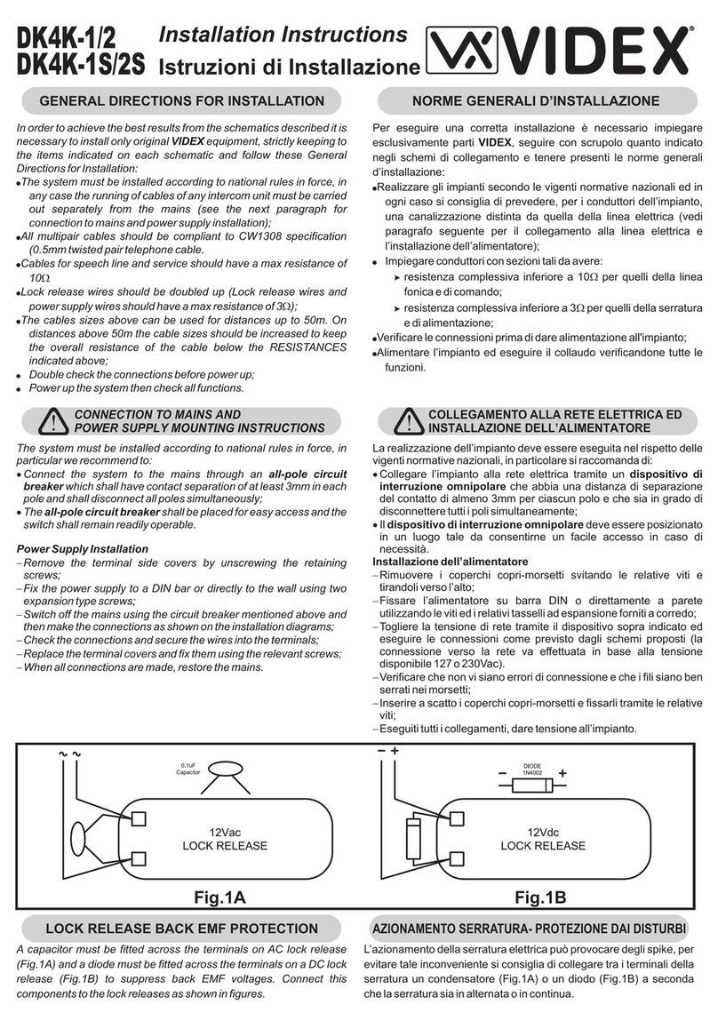
Si raccomanda
di far installare il presente dispositivo
esclusivamente da personale qualifi-
cato
We recommend
This equipment is installed by a
Competent Electrician, Security or
Communications Engineer
8835 1.0 05/10/07 13/01/11 -Pag.3/4
Si raccomanda
di far installare il presente dispositivo
esclusivamente da personale qualifi-
cato
We recommend
This equipment is installed by a
Competent Electrician, Security or
Communications Engineer
8835 1.0 05/10/07 13/01/11 -Pag.4/4
Factory - Office (All Countries Support)
VIDEX ELECTRONICS S.p.A. Via del lavoro,1 63020 MONTEGIBERTO (AP) - ITALY
Phone: (+39) 0734 - 631669 Fax: (+39) 0734 - 632475 www.videx.it e-mail: [email protected]
Northern UK Office (Only UK Support)
VIDEX LTD Unit 5-7 Chillingam Industrial Estate Chapman Street NEWCASTLE UPON TYNE Ne6 2XX
Phone: 0191 2243174 Fax: 0191 - 2241559 www.videx-security.com

This manual suits for next models

3

Other Videx Intercom System manuals

Videx 5188 User manual

Videx

Videx 5188 User manual

Videx VK4K/6256 Series System manual

Videx

Videx VK4K/6256 Series System manual

Videx VRVK Series System manual

Videx

Videx VRVK Series System manual

Videx Kristallo Series User manual

Videx

Videx Kristallo Series User manual

Videx 4000 Series User manual

Videx

Videx 4000 Series User manual

Videx VX2300 System manual

Videx

Videx VX2300 System manual

Videx KRV98 Instruction manual

Videx

Videx KRV98 Instruction manual

Videx 4000 Series User manual

Videx

Videx 4000 Series User manual

Videx 6388 User manual

Videx

Videx 6388 User manual

Videx 8000 Series User manual

Videx

Videx 8000 Series User manual

Videx IP videokit IPVK/6296 Series System manual

Videx

Videx IP videokit IPVK/6296 Series System manual

Videx 4000 Series User manual

Videx

Videx 4000 Series User manual

Videx SENTRY User manual

Videx

Videx SENTRY User manual

Videx VR4K-1/CL User manual

Videx

Videx VR4K-1/CL User manual

Videx 4000 Series User manual

Videx

Videx 4000 Series User manual

Videx 4000 Series 4384 User manual

Videx

Videx 4000 Series 4384 User manual

Videx SMK/N User manual

Videx

Videx SMK/N User manual

Videx 3000 Series User manual

Videx

Videx 3000 Series User manual

Videx 4836 User manual

Videx

Videx 4836 User manual

Videx 3000 Series User manual

Videx

Videx 3000 Series User manual

Videx DK4K-1S User manual

Videx

Videx DK4K-1S User manual

Videx GSM4K Series User manual

Videx

Videx GSM4K Series User manual

Videx 6200 Series User manual

Videx

Videx 6200 Series User manual

Videx 3000 Series User manual

Videx

Videx 3000 Series User manual

Popular Intercom System manuals by other brands

Rosslare AYC-E/Q60 Series instruction manual

Rosslare

Rosslare AYC-E/Q60 Series instruction manual

Bticino 322040 manual

Bticino

Bticino 322040 manual

MAS DP02HMNKG user manual

MAS

MAS DP02HMNKG user manual

Unitech Tashi MT200 Quick reference guide

Unitech

Unitech Tashi MT200 Quick reference guide

Toa VS-900TI Specifications

Toa

Toa VS-900TI Specifications

Sonifex AVN-TB20AR Handbook

Sonifex

Sonifex AVN-TB20AR Handbook

Opiz OP-D7D6-R user manual

Opiz

Opiz OP-D7D6-R user manual

Olympia VDB 824YA manual

Olympia

Olympia VDB 824YA manual

Bpt YVL200 UK Instructions for use and installation

Bpt

Bpt YVL200 UK Instructions for use and installation

CrewPlex MR10-900 operating manual

CrewPlex

CrewPlex MR10-900 operating manual

Fanvil i30 user manual

Fanvil

Fanvil i30 user manual

Aiphone IS SERIES manual

Aiphone

Aiphone IS SERIES manual

Me VISTADOOR VDV-1007 Assembly instructions

Me

Me VISTADOOR VDV-1007 Assembly instructions

Sentex Crown Jewel Programming manual

Sentex

Sentex Crown Jewel Programming manual

Eyevision EV-H298 manual

Eyevision

Eyevision EV-H298 manual

2easy DMR11-D8 quick start guide

2easy

2easy DMR11-D8 quick start guide

Honeywell ETCS operation instruction

Honeywell

Honeywell ETCS operation instruction

Xenon FEVER DEFENCE Assembly instructions

Xenon

Xenon FEVER DEFENCE Assembly instructions

manuals.online logo
manuals.online logoBrands
  • About & Mission
  • Contact us
  • Privacy Policy
  • Terms and Conditions

Copyright 2025 Manuals.Online. All Rights Reserved.