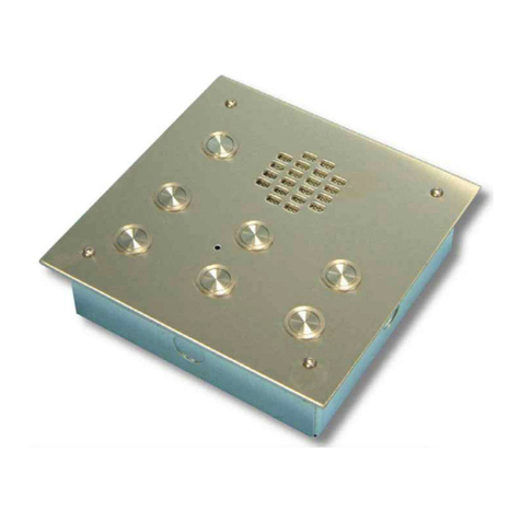
Videx VR120DK-1 User manual

THE POWER TO SECURE
TECHNICAL MANUAL EDITION 1.0
ONE BUTTON DOOR
ENTRY KIT
VR120DK-1

THE POWER TO SECURE
Page 2 VR120DK-1 TECHNICAL MANUAL EDITION 1.1
CONTENTS
PAGE
Manual Introducon 3
System Introducon 3
System Components 4 - 5
• 136 Amplier 4 - 5
Panel and Back Box Dimensions 6
Power Supply (Art.520M) 7
Audiophone (Art.3011) 7
Accessories 7 - 8
• Art.512A Extension Sounder 7
• ES/1 Extension Strobe 8
• Art.506N relay 8
Installaon 9
Cable Type and Cable Size Guide 9 - 11
Block Diagram 11
Panel and Back Box Installaon 12 - 13
Panel Care 13
Tesng the Installaon 14
Accessories Connecon Guide 14 - 15
Wiring Diagrams 16 - 17
• 1 buon audio panel with 1 audiophone 16
• 1 buon audio panel with 3 audiophones 17
Trouble Shoong Guide 18 - 19
Notes 19

THE POWER TO SECURE
Page 3
VR120DK-1 TECHNICAL MANUAL EDITION 1.1
MANUAL INTRODUCTION
The informaon in this manual is intended as an installaon and commissioning guide for the Videx
VR120 vandal resistant one buon audio intercom kit. This manual should be read carefully before
the installaon commences. Any damage caused to the equipment due to faulty installaons where the
informaon in this manual has not been followed is not the responsibility of Videx Security Ltd.
VIDEX run free training courses for engineers who have not installed this system before. Technical
help is also available on 0191 224 3174 during oce hours or via e-mail: tech@videxuk.com.
An electronic copy of this technical manual can be downloaded from the Videx website:
www.videxuk.com
SYSTEM INTRODUCTION
This audio kit will enable a caller at an entrance point to signal an occupant in the dwelling by pressing
a call buon which will send an electronic call tone to an audio telephone. A Yellow ‘SPEAK’ LED
will indicate the call has been answered and a two way conversaon can take place, the occupant can
release an electric lock release by pressing a buon on the telephone base unit. The kit does not include
the electric lock release. A 12V AC release should be used with this kit (The output for the lock is a dry
contact relay so any other type of lock can be used with an appropriate PSU). If this kit is to be used
with a gate, the dry contact output can be used to trigger the gate control board. DDA features such as
a ‘SPEAK’ LED, ‘BUSY’ LED, ‘DOOR OPEN’ LED and reassurance tone are standard on this kit.
A
ush back box is standard in this kit, however a ush stainless steel bezel back box and a surface
back box with rainshield are also available (see page 6).
Key Features
• 12 Gauge stainless steel.
• IP68 rated buon.
• SPEAK, BUSY and OPEN call progress LEDs.
• Call progress reassurance tone.
• Dry contact relay output for lock release or gate controller.
• Timed call, speech and lock release.
• Speaker and microphone volume adjustment.
This audio kit can be used for a single entrance system, however
it can be expanded to include mulple entrance panels.

THE POWER TO SECURE
Page 4 VR120DK-1 TECHNICAL MANUAL EDITION 1.1
SYSTEM COMPONENTS
This kit comprises of a ush or surface vandal resistant 1 buon door panel including a power supply
and audio telephone. Up to a maximum of three audio telephones can be used on this system to call
in parallel.
DOOR PANEL
An audio or video vandal resistant door panel will consist
of a 136 amplier module, buon connector board and
‘n’ number of buons. Addionally call buons can be
engraved to suite the apartment numbers.
Speaker module connecons, switches and jumper
Dip-Switches
The four way dip-switch bank has the following funcons.
Please note: dip-switches must be set before power up. Any
changes made when power is on will not take eect unl a
power down reset.
Speech Time
Switch 1 OFF 1 minute
Switch 1 ON 2 mintues
Relay Time
Switch 2 OFF
Switch 3 OFF 2 seconds Switch 2 ON
Switch 3 OFF 8 seconds
Switch 2 OFF
Switch 3 ON 4 seconds Switch 2 ON
Switch 3 ON 20 seconds
Speech Live
Switch 4 OFF Only when called
Switch 4 ON (only possible
on one door systems)
Speech live whenever
handset lied
Jumper
Jumper JP controls the reassurance tone volume level at the door panel.
adjustment for speech volume
at the apartment (microphone)
adjustment for speech volume level
at the door staon (speaker)
POTS
Speech volume adjustments are carried out at the door panel using a small trimmer driver.
Posion H High volume reassurance tone
Posion L Low volume reassurance tone
No Jumper No reassurance tone

THE POWER TO SECURE
Page 5
VR120DK-1 TECHNICAL MANUAL EDITION 1.1
VX136 Amplier Module VX136 Current Rang on +12Vdc
Connecon Funcon Condion Current (mA)
1 Receive speech from apartment Standby 18mA
2 Transmit speech to apartment System busy 58mA
+ +12Vdc input During a call 122mA
- 0V (Ground) Live speech 108mA
5 Switched 0V from phone to trigger door release relay Lock Release 125mA
TElectronic call tone output to common side of call buons Maximum 130mA
- 0V for use with push to exit input (PTE)
PTE Switched 0V input from push to exit buon to trigger door release relay
CCommon connecon of dry contact relay
NC Normally closed connecon of dry contact relay
NO Normally open connecon of dry contact relay
D+ External link to door open (+12V side) LED. Not used with this kit
D- External link to door open (0V side) LED. Not used with this kit
BSY Busy signal for use with mulple door systems (Normally high, 12V. Low when busy 0V)
SL Switched 0V output to switch on video PSU. (0V throughout a call, open collector in standby)
F1 Switched 0V output to switch on camera. (0V throughout a call, open collector in standby)
mic
4 way dip-switch
reassurance tone jumper
mic and speaker
volume POTS
terminal connecons

THE POWER TO SECURE
Page 6 VR120DK-1 TECHNICAL MANUAL EDITION 1.1
PANEL AND BACK BOX DIMENSIONS
There are three VR120 panel back box opons available, a standard ush back box, a ush back box
with bezel and a surface back box with rainshield (see below).
FLUSH (VRFB120x220)
FRONT PANEL
SURFACE WITH
RAINSHIELD
(VRSB120x220)
FLUSH WITH BEZEL
(VRBB120x220)

THE POWER TO SECURE
Page 7
VR120DK-1 TECHNICAL MANUAL EDITION 1.1
POWER SUPPLY
The standard power supply in this kit is the Art.520M. Outputs of 12Vdc (200mA max), 8Vdc (300mA
max) and 13Vac (1A max) are available. The dc outputs are designed to power the amplier module
only and cannot be used to power other devices such as code locks, lock releases etc. These items must
be connected to the AC output of this power supply.
Terminal Funcon
+12 12Vdc output (200mA max.)
+ 8Vdc output (300mA max.)
- 0V (Ground)
~13Vac (1A max.)
230V~Mains in (Live connecon)
0V Mains in (Neutral connecon)
Art.520M
AUDIOPHONE
Art.3011
T
he Art.3011 audiophone is a smart line electronic call tone phone
and includes a lock release push buon and a 3 level call tone
volume switch and requires a minimum of 5 cores for connecon.
Terminal Funcon
1 Transmit speech to the door panel
2 Receive speech from the door panel
3 0V (Ground)
4 Electronic call tone input
5 Lock trigger (Switched 0V)
6 Not used
Other audiophones that can be used with this kit are the Art.3111
(spare service buon) and the Art.3112 (spare service buon and mute
switch).
ACCESSORIES
The Art.512A is an extension sounder that can be wall mounted and will ring whenever
the audiophone it is connected to rings. The 512A requires an electronic calltone
input.
Art.512A
Terminal Funcon Condion Current Rang (mA)
4 Calltone input During a call 100mA
- 0V (GND) Max 105mA
Connecons
Fuse
compartment
Art.3011
terminal
connecons
Art.512A
3 level call
tone switch

THE POWER TO SECURE
Page 8 VR120DK-1 TECHNICAL MANUAL EDITION 1.1
The ES/1 is a med strobe unit for the hard of hearing or can be used in noisy environments. The strobe will
ash when a call is received and will connue ashing for an adjustable me period or unl the reset buon is
pressed. It requires a 12Vac or dc power input and the adjustable me period can be set between 2 - 100 seconds.
ES/1 Extension Strobe
Connecons
The Art.506N universal boxed 12/24V ac/dc double pole relay can be used for many funcons. Its changeover
relay contacts are rated at 240Vac 5A. It also includes low current transistor switched inputs (+posive and
-negave triggers). The Art.506N relay can also be used to switch a volt free contact to a gate or barrier controller
and also used to drop power o to a fail safe mag lock.
Art.506N relay
Terminal Funcon
1 24V ac or DC input
2 12V ac or DC input
3 0V switched input (link to GND when not using terminal 4)
4Switched +posive input
5GND (0V power when using switched +posive input)
CO1 Common relay 1 connecon
Max. current and
voltage for each relay
5A @ 230Vac
NO1 Normally open relay 1 connecon
NC1 Normally closed relay 1 connecon
CO2 Common relay 2 connecon
NO2 Normally open relay 2 connecon
NC2 Normally closed relay 2 connecon
Connecons
Terminal Funcon Condion Current Rang (mA)
Power 12Vac or dc input Standby 6.6mA
I/P +posive trigger During a call 160 - 175mA
+O/P 12Vdc output Max 180mA
GND 0V (ground)
Reset Switched 0V reset
NC Normally closed relay connecon
CO Common relay connecon
NO Normally open relay connecon
ES/1
Art.506N

THE POWER TO SECURE
Page 9
VR120DK-1 TECHNICAL MANUAL EDITION 1.1
INSTALLATION
Inial Installaon Checks
The wiring diagrams towards the back of this manual should be followed carefully. Heavy duty
conductors on wiring diagrams are shown heavily outlined in some instances where voltage drop is
experienced then these wires should be doubled up.
• Check that all components are free from damage before installing (Do not proceed with the instal-
laon in the event of damage).
• Keep all packaging away from children.
• Do not obstruct the venlaon openings or slots on any of the devices.
• All connecons to mains voltages must be made to the current naonal standards (IEE Wiring regu-
laons)
• Install an appropriate fused spur or isolaon switch to isolate the mains.
• Isolate the mains before carrying out any maintenance work on the system.
• All intercom and access control cables must be routed separately from the mains.
Lock Release Wiring and Back EMF Protecon
When ng an electric lock release back EMF protecon will be required. If ng an AC lock release
then a 100nF ceramic disc capacitor must be ed across the terminals on the lock. If ng a DC
lock release (fail secure or fail safe) then a 1N4002 diode must be ed across the terminals on the lock.
CABLE TYPE AND CABLE SIZE GUIDE
The following cable types described below are measured in mm² for the cross seconal area (CSA) for
each conductor (core) within the cable bundle. The tables show the distances in metres between
system components. All cable types are catagorised using the AWG (American Wire Gauge).
Suitable cables for this system are a BT type telephone cable CW1308 and a YY cable (other similar or
equivalent cables are also suitable). When selecng a parcular cable type care must be taken to ensure
that excessive voltage drop is avoided and the lowest possible resistance is achieved. Use the following
cable types and the tables as a guide to ensure that the best possible performance is achieved.
Cable Types

THE POWER TO SECURE
Page 10 VR120DK-1 TECHNICAL MANUAL EDITION 1.1
CW1308 Telephone cable (CSA 0.22mm² AWG 24 - Maximum Resistance 97.8 Ohm/km)
CW1308 is an internal grade cable and is available in 3 pair, 4 pair, 6 pair, 10 pair, 12 pair, 15 pair, 20 pair
and 25 pair.
CW1308B Telephone cable (CSA 0.22mm² AWG 24 - Maximum Resistance 97.8 Ohm/km)
CW1308B is an internal or external grade cable (if used externally must be protected) and is available in
10 pair and 20 pair.
CW1128 Telephone cable (CSA 0.22mm² AWG 24 - Maximum Resistance 96 Ohm/km)
CW1128 is an external grade poly-lled cable (if used externally must be protected) and is available in 2
pair, 5 pair, 10 pair and 20 pair.
CW1128 / CW1198 Telephone cable (CSA 0.5mm² AWG 20 - Maximum Resistance 91 Ohm/km)
CW1128 / CW1198 is an external grade poly-lled armoured cable (for direct burial) and is available in
2 pair, 5 pair, 10 pair and 20 pair.
CAT5e (CSA 0.2mm² AWG 24 - DC loop resistance <0.188 Ohm/m, converts to 94 Ohm/km)
CAT5e is an internal grade cable and is available in 4 pair. Please note that if CAT5e cable is going to be
used then the DC characteriscs above must be met by measuring the resistance of the cable directly or
by consulng the manufacturer’s datasheet.
YY Control Cable
(CSA 0.5mm² AWG 24 - Maximum Resistance 39 Ohm/km)
(CSA 0.75mm² AWG 18 - Maximum Resistance 26 Ohm/km)
(CSA 1.0mm² AWG 17 - Maximum Resistance 19.5 Ohm/km)
(CSA 1.5mm² AWG 15 - Maximum Resistance 13.3 Ohm/km)
(CSA 2.5mm² AWG 13 - Maximum Resistance 8 Ohm/km)
YY control cable is an internal or external grade cable (if used externally must be protected) and is
available in 4 Core, 7 Core, 12 Core & 18 Core. Each cable comes with numbered cores in white on a
black sheath and also includes a green/yellow earth core.
Connecons from door panel to Audiophone
Connecon 50m 100m 200m 300m 400m
Power 0.35mm² 0.5mm² 0.75mm² 1.0mm² 1.5mm²
All others 0.25mm² 0.35mm² 0.5mm² 0.75mm² 1.0mm²
Maximum acceptable resistance for power terminal connecons = 5 Ohms or less, for all other
connecons = 10 Ohms or less for best possible performance.
Connecons for power supply output to door panel and lock release
50m 100m
Connecon 0.5mm² 0.75mm²
The power supply ideally should be located as close to the door panel as possible, typically between
20 - 30m. Maximum acceptable resistance for above connecons = 3 Ohms or less for best possible
performance.

THE POWER TO SECURE
Page 11
VR120DK-1 TECHNICAL MANUAL EDITION 1.1
Audiophone Cable
Model Min.
Cores
50m 100m 200m 300m 400m 500m
Art.3011 5 4 pair CW1308
or CAT5e
6 pair CW1308 or
7 core 0.5mm² YY
10 pair CW1308 or
12 core 0.5mm² YY
12 pair CW1308 or
12 core 0.5mm² YY 12 core 0.5mm² YY 12 core 1.0mm² YY
Art.3111 5 4 pair CW1308
or CAT5e
6 pair CW1308 or
7 core 0.5mm² YY
10 pair CW1308 or
12 core 0.5mm² YY
12 pair CW1308 or
12 core 0.5mm² YY 12 core 0.5mm² YY 12 core 1.0mm² YY
Art.3112 5 4 pair CW1308
or CAT5e
6 pair CW1308 or
7 core 0.5mm² YY
10 pair CW1308 or
12 core 0.5mm² YY
12 pair CW1308 or
12 core 0.5mm² YY 12 core 0.5mm² YY 12 core 1.0mm² YY
Whenever possible the speech line connecons 1 and 2 (refer back to page 7) should be twisted with
the speech GND connecon as pairs. Maximum acceptable resistance for power terminal connecons =
5 Ohms or less, for all other connecons = 10 Ohms or less for best possible performance.
It should be noted that if a mul-core cable is used and the overall resistance of the cable is higher
than that stated above it is possible to double up on core connecons to both increase the CSA of the
connecon and reduce the overall resistance of the cable.
High Voltage and Low Voltage Cables
When laying high voltage cables (mains) and low voltage cables (intercom and signal) they should
always be routed separatley in dierent ducng. If for any reason they are in the same ducng
whether internally or externally they should always be kept separate whithin the ducng itself, typically
there should be a gap of approximately 12” (inches) between the sets of high voltage and low voltage
cables. If necessary they should be cable ed o to keep them as far apart as possible.
BLOCK DIAGRAM
Audio System Block Diagram
Addional cores will be required for auxiliary devices such as push to exit buons, reman switches, fail
safe lock release etc. If more than one intercom panel is being used then an addional core for the busy
(BSY) connecon between intercom panels will be required.

THE POWER TO SECURE
Page 12 VR120DK-1 TECHNICAL MANUAL EDITION 1.1
PANEL AND BACK BOX INSTALLATION
The following guide lines should be followed with respect to the installaon and care of the VR120
panel and accompanying back box. The back box should be adequately secured to the wall to pre-
vent risk of injury.
• To prevent water ingress to the VR120 panel ensure that a good seal between the back box and the
face plate itself is made. The neoprene seal on the face plate will oer this as long as the back box
front is ush with the wall surface. Always ensure the panel is ghtened suciently to compress the
neoprene seal.
• In the event of gaps due to uneven walls we suggest using a silicon sealant be used. In the event of
water ingress to the back box we would also suggest drilling 3x4mm holes at the boom of the back
box to allow any collecon of water to escape.
• Always ensure all cable entry points are suciently sealed to prevent water ingress (refer to Fig.1,
Fig 2 and Fig.3). All cables should loop down and then back up to the terminaon connecons to
avoid any water travelling along the cable and onto the pcb.
Fig.1
Fig.2
FRONT VIEW REAR VIEW
FLUSH BACK BOX (VRFB120x280)
BEZEL BACK BOX (VRBB120x280)
FRONT VIEW REAR VIEW

THE POWER TO SECURE
Page 13
VR120DK-1 TECHNICAL MANUAL EDITION 1.1
PANEL CARE
The VR120 door panel is manufactured from brushed 12 Gauge 304 grade stainless steel. It is important
that the facia is cleaned on regular occasions to prevent dirt build up and tarnishing of the metal. A
general household metal polish can be used but care should be taken to follow the grain of the metal
when polishing and always only polish in one direcon with a so cloth to avoid light scratching of the
facia. Also try to avoid any polish build up around the call buon which may prevent the buon from
operang correctly.
Cleaners that cannot be used:
To Clean Method
Finger prints Detergent and warm water or a household polish.
Roune cleaning Soap, detergent or dilute (1%) ammonia soluon in warm water.
Staining and discoloura-
on
Mild non-scratching creams and polishes. Take care to avoid build up of
creams in the buons which could cause scking.
The table below idenes the methods of cleaning.
• Chloride containing cleaners.
• Hydrochloric acid based cleaners.
• Sidol stainless steel cleaner (can aect engraving).
• Hydrochloride bleaches.
• Silver cleaners.
Fig.3
REAR VIEW
SURFACE BACK BOX WITH RAINSHIELD (VRSB120x280)

THE POWER TO SECURE
Page 14 VR120DK-1 TECHNICAL MANUAL EDITION 1.1
TESTING THE INSTALLATION
• Check all the connecons have been made correctly and are terminated properly into the terminals
and then power up the system.
• Check the voltage outputs on all of the terminals of the Art.520M power supply.
• Call all the apartments in turn. Check for the call tone to the apartment, speech in both direcons
and that the lock release operates when the lock buon on the audiophone is pressed.
• If the volume of speech needs to be adjusted, this can be done by adjusng the volume POTs on
the rear of the VX136 amplier at the door panel.
• If the call tone volume needs adjusng this can be done at each handset by adjusng the 3 level
volume control switch on the side of the audiophone (refer back to page 7).
Safety Note: The VR120 panel must be earthed to its back box (with the earth strap provided in the kit)
and then the back box earthed to the buildings earth connecon.
ACCESSORIES CONNECTION GUIDE
Below shows how to connect an extension sounder (Art.512A) and an extension strobe (ES/1) when
ed to an audio system. In some instances a separate 12Vdc power supply may be required when
connecng an extension strobe when several 12Vdc devices are connected on the system, this is to
avoid excessive current draw on the exisng power supply.
earth strap
connecon
Extension Sounder

THE POWER TO SECURE
Page 15
VR120DK-1 TECHNICAL MANUAL EDITION 1.1
Extension Strobe
Push to Exit (push to make)
Dry Relay Contacts (Art.506N Relay)

THE POWER TO SECURE
Page 16 VR120DK-1 TECHNICAL MANUAL EDITION 1.1
WIRING DIAGRAMS
1 way audio system with a VR120/136-1 door
panel connected to an Art.3011 audiophone.

THE POWER TO SECURE
Page 17
VR120DK-1 TECHNICAL MANUAL EDITION 1.1
1 way audio system with a VR120/136-1
door panel connected to three Art.3011
audiophones.

THE POWER TO SECURE
Page 18 VR120DK-1 TECHNICAL MANUAL EDITION 1.1
TROUBLE SHOOTING GUIDE
Symptom Test
No speech from the door panel to
the telephone (speech line 2).
Check terminal 2 on the amplier for connuity to terminal 2 on the telephone.
During a call but before liing the handset, check the voltage from terminal 2 of the
136 amplier is 12Vdc. Trace this voltage to terminal 2 to the telephone.
Check the voltage drops to approx. 1Vdc aer the handset is lied. (If not try another
telephone).
If all else fails try another 136 amplier at the door staon.
No speech from the telephone to
the door panel (speech line 1).
Check terminal 1 on the 136 amplier on the door panel for connuity back to terminal
1 on the telephone.
During a call but before liing the handset, check the voltage to on terminal 1 of the
136 amplier is 12Vdc. Trace this voltage to terminal 1 to the telephone.
Check the voltage drops to approx. 4Vdc aer the handset is lied. (If not try another
telephone).
If all else fails try another 136 amplier at the door staon.
No speech in either direcon. Check for 230v AC mains input to power supply (Art.520M).
Check the 315mA fuse in the power supply.
Check for 12Vdc across terminals + & - on the door panel 136 amplier. This should be
there all the me and comes directly from the PSU (Art.520M).
Check for connuity of both speech line cables, terminals 1 and 2 between the 136
amplier to the audiophone or videophone.
Lock will not operate from
telephone.
Check the door open LED comes ON when the lock buon is pressed on the audiophone
or videophone (only aer speech is live to the handset).
Check there is 12Vdc on the + and – terminals of the 136 door amplier.
Check for connuity across the 136 amplier relay contacts C/NO when the lock buon
is pressed on the audiophone or videophone.
Check for connuity across the 136 amplier relay contacts C/NO when the PTE input
has been triggered by a PTE buon or by shorng out terminals PTE and – on the 136
amplier.
If using a fail secure lock release check for voltage across the lock when the lock buon
of the audiophone or videophone is pressed (only aer speech is live to the handset) or
when the PTE input is acvated.
If using a fail safe lock release check the voltage across the lock drops o when the
lock buon of the audiophone or videophone is pressed (only aer speech is live to the
handset) or when the PTE input is acvated.
Nothing happens when any call
buon is pressed.
Check for connuity across the push buon terminals.
Check terminal T on the 136 amplier for call tone voltage 10-12Vdc.
Check the common of the buons has 10-12Vdc present at all mes.
When trouble shoong on this system it will be easier to break the system down to a manageable
size. The simplest way to do this is to remove all but one handset (if more than 1 handset has been
connected). Doing this you can conrm the door panel and control equipment are free from faults. Once
this has been conrmed you can reconnect the addional handsets one by one and then test the system
again each me to see if the fault has re-appeared.

THE POWER TO SECURE
Page 19
VR120DK-1 TECHNICAL MANUAL EDITION 1.1
Symptom Test
Nothing happens when a call
buon is pressed.
Check for connuity on the call wire between the call buon on the door panel to the
call tone input terminal on the audiophone.
When the call buon is pressed you should be able to read 10-12Vdc on terminals 3 &
4 of the Art.3011 audiophone (4 of the audiophone comes direct from the call buon).
Hum on the speech lines. Ensure all intercom cables do not run close to higher voltage cables i.e. mains cables.
Try another 136 amplier at the door panel.
NOTES:

THE POWER TO SECURE
TECHNICAL MANUAL EDITION 1.1
Northern Oce
Videx Security Ltd.
Unit 4-7 Chillingham Industrial Estate
Newcastle Upon Tyne
NE6 2XX
Southern Oce
Videx Security Ltd.
1 Osprey, Trinity Park
Trinity Way’ London
E4 8TD
TECHNICAL SUPPORT
Tel: 0191 224 3174
Fax: 0191 224 4938
Email: tech@videxuk.com
Web: www.videxuk.com
Table of contents
Other Videx Intercom System manuals

Videx
Videx GSM4K/4G User manual

Videx
Videx 3000 Series User manual

Videx
Videx Smart Series User manual

Videx
Videx 4000 Series User manual

Videx
Videx VRVK Series System manual

Videx
Videx 6200 Series User manual

Videx
Videx 2 Wire User manual

Videx
Videx VK4KX System manual

Videx
Videx Videokit CVK4K User manual

Videx
Videx 4000 Series User manual

Videx
Videx VK4K/6358 Series System manual

Videx
Videx ESVK 6388 Series System manual

Videx
Videx 4000 Series User manual

Videx
Videx VK4K Series System manual

Videx
Videx VK8K System manual

Videx
Videx 5178 User manual

Videx
Videx 6358 System manual

Videx
Videx VRVK Series System manual

Videx
Videx SENTRY User manual

Videx
Videx 4000 Series User manual