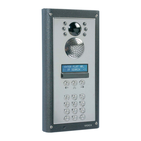
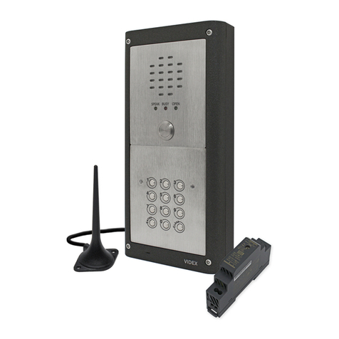
Videx 800 Series User manual


- Introduction and electric symboles - - - - - - - - - - - - - - - -1
- Intercoms - - - - - - - - - - - - - - - - - - - - - - - - - - - - - - - - - - -2
- Intercoms with selection push buttons - - - - - - - - - - - - -3
- Modular push button panels series 800 - - - - - - - - - - - - -4
- Power supplies - accessories - - - - - - - - - - - - - - - - - - -11
- General directions for installation
testing of installation - Trouble shooting guide - - - - - - -15
- Intercom system with n... users
and one outdoor station - - - - - - - - - - - - - - - - - - - -18-19
- Intercom system with two automatically switched
outdoor stations - - - - - - - - - - - - - - - - - - - - - - - - - - -20-21
- Intercom system with n... automatically switched
outdoor stations - - - - - - - - - - - - - - - - - - - - - - - - - - -22-23
- Intercom system with n... users and one outdoor station
with full privacy of speech and lock opening - - - - -24-25
- Intercom system with n... users
and one outdoor station (1+1 system) - - - - - - - - - -26-27
- Two way intercommunicating system - - - - - - - - - - -28-29
- Two way intercommunicating system
plus outdoor station - - - - - - - - - - - - - - - - - - - - - - - -30-31
- Intercommunicating system
with max. 6 extensions - - - - - - - - - - - - - - - - - - - - - -32-33
- Intercommunicating system
with 5 extensions plus outdoor station - - - - - - - - - -34-35
- Intercommunicating system
with 11 extensions - - - - - - - - - - - - - - - - - - - - - - - - -36-37
- Intercommunicating system with 10 extensions plus
outdoor station - - - - - - - - - - - - - - - - - - - - - - - - - - -38-39
- Intercommunicating system with 5 extensions plus
two automatically switched outdoor stations - - - - - -40-41
- Intercommunicating system with 5 or 10 extensions plus
automatically switched outdoor stations - - - - - - - - -42-43
- Intercom systems with digital door
opening keypad - - - - - - - - - - - - - - - - - - - - - - - - - -44-45
- Intercom systems with
proximity reader (VPROX) - - - - - - - - - - - - - - - - - - - -46-47
- Prefazione - Simboli elettrici - - - - - - - - - - - - - - - - - - - - -1
- Citofoni - - - - - - - - - - - - - - - - - - - - - - - - - - - - - - - - - - - -2
- Intercomunicanti - - - - - - - - - - - - - - - - - - - - - - - - - - - - -3
- Pulsantiere modulari serie 800 - - - - - - - - - - - - - - - - - - -4
- Alimentatori ed accessori - - - - - - - - - - - - - - - - - - - - - -11
- Norme generali di installazione
collaudo impianto - Ricerca guasti - - - - - - - - - - - - - - -15
- Impianto citofonico n utenti
con un posto esterno - - - - - - - - - - - - - - - - - - - - - - -18-19
- Impianto citofonico con due posti esterni
scambiabili automaticamente - - - - - - - - - - - - - - - - -20-21
- Impianto citofonico con n posti esterni
scambiabili automaticamente - - - - - - - - - - - - - - - - -22-23
- Impianto citofonico n utenti con
segreto di conversazione - - - - - - - - - - - - - - - - - - - -24-25
- Impianto citofonico n utenti
con 1 posto esterno sistema 1+1 - - - - - - - - - - - - - -26-27
- Impianto intercomunicante con 2 citofoni - - - - - - - -28-29
- Impianto intercomunicante con 2 citofoni
più posto esterno - - - - - - - - - - - - - - - - - - - - - - - -30-31
- Impianto intercomunicante
con 6 citofoni - - - - - - - - - - - - - - - - - - - - - - - - - - - -32-33
- Impianto intercomunicante con 5 citofoni
più posto esterno - - - - - - - - - - - - - - - - - - - - - - - - -34-35
- Impianto intercomunicante
con 11 citofoni - - - - - - - - - - - - - - - - - - - - - - - - - - -36-37
- Impianto intercomunicante con 10 citofoni
più posto esterno - - - - - - - - - - - - - - - - - - - - - - - - -38-39
- Impianto intercomunicante con 5 citofoni
più 2 posti esterni - - - - - - - - - - - - - - - - - - - - - - - - -40-41
- Impianto intercomunicante con 5 o 10 citofoni
ed n posti esterni - - - - - - - - - - - - - - - - - - - - - - - - -42-43
- Impianti citofonici
con tastiera digitale apriporta - - - - - - - - - - - - - - - - -44-45
- Impianti citofonici
con lettore di prossimità - - - - - - - - - - - - - - - - - - - -46-47
INDICE Pag.INDEX Page

11
PREFAZIONE
In questo manuale sono presentati prodotti e schemi di impianto per i
citofoni Serie 900, SMART e le pulsantiere modulari Serie 800
SUDDIVISIONE IMPIANTI
a) Impianti citofonici: Sono impianti per edifici con un numero qua-
lunque di utenti in cui é possibile conversare con il posto esterno.
Collegamenti con sistema di fili 4+1 o 1+1.
b) Impianti citofonici intercomunicanti: Sono impianti in cui é pos-
sibile conversare sia con il posto esterno che con un altro posto
interno.
N.B. - Si raccomanda di rispettare scrupolosamente, in fase di
installazione, gli schemi di impianto e di leggere attentamente
tutte le NOTE E I FOGLI DI ISTRUZIONE ALLEGATI A CIASCUN
PRODOTTO. Gli schemi di impianto presentati sono i più comuni;
nel caso si richiedano soluzioni diverse consultare il nostro Ufficio
Tecnico. Tutte le misure riportate sono in mm.
MARCATURA CE
La marcatura CE di conformità indica che il prodotto soddisfa ai requi-
siti richiesti dalle Direttive della Comunità Economica Europea
(CEE) 93/68 attualmente in vigore.
In particolare la marcatura CE apposta sui prodotti descritti nel presen-
te manuale indica che lo stesso prodotto è conforme alle direttive, ad
esso applicabili, per la:
-Compatibilità Elettromagnetica (EMC) CEE 89/336 e CEE 92/31
con riferimento alle norme standard
EN 50081 – 1 ed EN 50082 – 1.
-Sicurezza Elettrica Bassa Tensione (LVD) CEE 73/23 con riferi-
mento alle norme standard EN 60065
EN 60742 ed EN 61558.
In presenza di campi elettromagnetici di forte intensità è possibile che
gli apparati possano subire un leggero degrado delle prestazioni
audio.
INTRODUCTION
The Technical Manual gives a selection of connection diagrams and
fixing instructions using intercoms Series, 900 SMART and the modular
push button panels Series 800.
WIRING DIAGRAMS SUBDIVISION:
a) Door Entry Systems: Installations for systems with any number of
telephones. From the telephone it is possible to talk with one or
more outdoor stations and to open the door if required.
Wiring with 4+1 or 1+1 system.
b) Intercommunicating Systems: Installations using telephone with
selection keys with possibility of connection to one or more out-
door stations.
Note - Before and during installation carefully read and check all
notes and connection diagrams supplied with main equipment
and accessories. The diagrams and connections shown are for
standard systems; for special systems contact our Technical
Office.
All dimensions are in mm unless otherwise specified.
CE-MARKING DIRECTIVE
The CE-marking of conformity indicates that the item complies with the
requirements of the European Directives 93/68/EEC now in force.
In particular the CE-marking on the items described in this manual indi-
cates that the item complies with the directives that apply to it for:
- Electromagnetic Compatibility (EMC)
89/336/EEC and 92/31/EEC with
reference to the following standards:
EN 50081-1 and EN 50082-1
-Low Voltage Electric Safety (LVD)
73/23/EEC with reference to the following standards: EN 60065,
EN 60742 and EN 61558.
With electromagnetic fields of high intensity it can happen that the devi-
ces degrade lightly their audio performances.
ELECTRIC SYMBOL
SIMBOLI ELETTRICI
Led
Led
Condenser microphone
Microfono a condensatore
AC Buzzer
Ronzatore in AC
AC Extra bell
Suoneria supplementare in AC
Bulb
Lampadina
Earphone / loudspeaker
Auricolare / Altoparlante
Electronic switch
Commutatore elettronico
AC electric lock
Serratura elettrica in AC
Amplifier
Amplificatore
Push - button
Tasto in chiusura comandato manualmente
Relay
Relè con contatto normalmente aperto
Deviation box
Scatola di deviazione
Hook switch
Commutatore a slitta comandato meccanicamente

2
CITOFONI
Art. 924
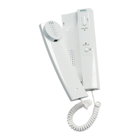
citofono in plastica ABS colore bianco, ronzatore 12Vac, pulsante apri-
porta ,predisposto per chiamata elettronica, microfono a conden-
satore. Da installare a muro mediante due viti e relativi tasselli ad
espansione o da tavolo utilizzando la base zavorrante Art. 938.
Morsetti serrafilo a vite.
Morsettiera
1Microfono
2Auricolare
3Massa
4Ingres. chiam. elettron
5Apriporta
6Ronzatore 12Vac
TELEPHONES
Art. 924
Standard doorphone in ABS plastic case colour white, with 12Vac buz-
zer, door opening button , input for an electronic call tone,
codenser microphone.
Wall mounting by two expansion type screws or directly to standard
round type Ø 60MM embedding box or standard rectangular (American
type) embedding box. Desk mounting by means of the Desk Kit Art.
938.
Terminals: Screw and nut type.
Connecting terminals:
1Microphone
2Receiver (earphone)
3Ground
4Input electronic tone
5Door opener
6Buzzer 12Vac
Art. 924
Art. 926
Art. 926
citofono come articolo precedente ma con
pulsante di servizio
Morsettiera
1Microfono
°
°
8Pulsante di
9Servizio
Art. 926
doorphone as Art. 924 but with servi-
ce button
Connecting terminals:
1Microphone
°
°
8service
9button
Art. 924S
Citofono come Art. 924 ma per impianti con segreto di conversazione.
Possibilità di selezionare due livelli del segnale di chiamata.
Art. 926S
Citofono come articolo precedente ma con pulsante di servizio .
Art. 924MS
Citofono come Art. 924S ma con in più un tasto per disattivare il
segnale di chiamata.
Art. 924S
As Art. 924 but incorporating privacy of speech and lock opening.
Art. 926S
Doorphone as Art. 924S but with service button .
Art. 924MS
As Art. 924 but with call tone ON-OFF switch.
Art. 925 - 925S
Art. 925
Citofono per impianti 1+1. Chiamata elettro-
nica.
Art. 925S
Citofono come Articolo precedente ma con
segreto di conversazione e di apertura ser-
ratura elettrica.
Morsettiera
1Fonia, chiamata, comando serratura
3Comune
Art. 925
Doorphone for 1+1 systems. Electronic
tone only.
Art. 925S
As Art. 925 but incorporating full lock and
speech privacy.
Connecting terminals:
1Speech, call, lock command.
3Common.

3
Art. SMART 1
Art. SMART 1
Citofono in plastica ABS colore bianco, ron-
zatore 12Vac, pulsante apriporta, predispo-
sto per chiamata elettronica, microfono a
condensatore. Da installare a muro median-
te due viti e relativi tasselli ad espansione.
morsetti serrafilo a vite.
Morsettiera
1Microfono
2Auricolare
3-7 Massa
4Ingres. chiamata elettron.
5Apriporta
6Ronzatore 13Vac.
Art. SMART 1
Standard doorphone in ABS plastic case
colour white, 12 Vac buzzer, door opening
button, predisposed for electronic call, con-
denser microphone. Wall mounting by two
expansion type screws.
Screw terminals.
Connecting terminals:
1Microphone
2Receiver (earphone)
3-7 Ground
4Input electronic call
5Door opener
612 Vac Buzzer
Art. SMART 2
Art. SMART 2
Citofono come articolo precedente ma con
pulsante di servizio.
Morsettiera
1Microfono
“
“
8pulsante di servizio
9
Art. SMART 2
Doorphone as Art. Smart 1 but with ser-
vice button.
Connecting Terminals
1Microphone
“
“
8service button
9
INTERCOMUNICANTI
Art. 928-5
Intercomunicante con 1 pulsante apriporta e 4 pulsanti di chiamata, in
plastica ABS colore bianco, chiamate interne con nota elettronica
modulata, microfono a condensatore. Da installare a filo muro median-
te due viti e relativi tasselli ad espansione o da tavolo utilizzando la
base zavorrante Art. 938.
Morsettiera
AMicrofono
BAuricolare.
XIngres. chiam. elettron.
-
Massa.
TComune pulsanti.
PPulsante apriporta o di chiamata
1
2Pulsanti di chiamata
3
4
RRonzatore RZ/102 per eventuale
-
chiamata dal posto esterno
Art. 928-10
Intercomunicante con 1 pulsante apriporta
e 9 pulsanti di chiamata. Stesse caratteristi-
che articolo precedente.
Morsettiera
AMicrofono.
°
°
Pulsanti di chiamata
7
8
9
RRonzatore RZ/102 per eventuale
-
chiamata dal posto esterno
INTERCOMS WITH SELECTION PUSH BUTTONS
Art. 928-5
Intercom set in ABS plastic case colour white, with one door opening
button, and 4 push buttons for internal communication plus outside sta-
tion if required, condenser microphone, electronic tone for internal
calls. Wall mounting by two expansion type screws. Desk mounting by
means of the Desk Kit Art. 938.
Connecting terminals:
AMicrophone
BReceiver (earphone)
XInput electronic call
-
Ground
TCommon push buttons
PDoor opening button. Or call buton.
1
2Call push buttons
3
4
RTerminals for buzzer Art. RZ/102
-
necessary in case of call from the
outdoor station
Art. 928-10
Intercom set as Art. 928-10 with door ope-
ning button and 9 push buttons.
Connecting terminals:
AMicrophone
°
°
Call push buttons
7
8
9
RTerminals for buzzer Art. RZ/102
-
necessary in case of call from the
outdoor station
Art. 928-10
Art. 928-5

4
MODULAR PUSH BUTTON PANELS
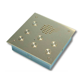
SERIES 800
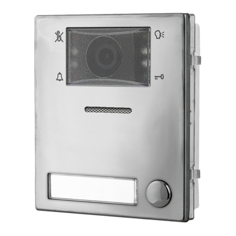
This new range consists of a series of modules in conjunc-
tion with special supports complete with back box or with
supports complete with surface mounting box. The appro-
priate assembling of the various modules with the front sup-
ports allows any size of front door panel with many different
configurations.. The various items of the system can be
identified with following groups:
- Modules
- Front supports complete with opening hinge and
back box
- Surface mounting box.
ACCESSORIES:
- Covering frames.
- Rainshields
Features of modules
Push buttons are protected and reinforced with a plate in stainless
steel, while modules front plates are in:
SStandard-Stainless Steel
AAli
WWhite
BBrown
BZ Bronze
Card name illumination on:
- Door station modules with 2 leds
- Call modules and information modules with lamp 24V 3W
All modules have same dimensions (119X97X29) and can be subdivi-
ded in four groups:
- Speaker Units
- Extension Front Panels
- Information Modules
- Access control Modules
SPEAKER UNIT MODULES
1+1 systems
Art. 835M-0/.. With 0 call buttons.
Art. 835M-1/.. With 1 call button.
Art. 835M-2/.. With 2 call buttons
Art. 835M incorporates in a small space following circuits:
A- Rectifier and voltage regulator.
B- Modulated tone generator.
C- Transmitting amplifier with condenser microphone.
D- Receiving amplifier with “VOLUME” control.
E- Balance circuit with “BALANCE” control to avoid the
Larsen effect.
F- Voltage discriminator to guarantee a full lock
and speech
privacy.
G- 2 leds to illuminate the card name.
Connecting terminals
D- Common speech
D1 - Common speech Diode for additional
extension panel.
- Power input 13Vac.
- Power output 13Vac for the electric lock.
S- Output, command to activate the electric lock.
3- Ground (Common wire).
- Power input 13Vac.
P2 - Speech, call user No.2, command electric lock.
P1 - Speech, call user No.1, command electric lock.
C- Output, common call buttons
C1 - Common push buttons
PULSANTIERE MODULARI
SERIE 800
Sono costituite da una serie di moduli da inserire su appo-
siti supporti completi di scatole da incasso o su supporti
portamoduli completi di scatola di protezione per montag-
gio a filo muro. Assemblando opportunamente i vari modu-
li si ha la possibilità di realizzare pulsantiere di ogni tipo e
configurazione. Il sistema comprende i seguenti gruppi di
particolari:
- Moduli
- Sostegni portamoduli completi di scatola da incasso
- Scatole di protezione per montaggio filo muro complete di sostegni
portamoduli
ACCESSORI:
- Cornici decorative in alluminio
- Tettucci antipioggia per scatole da incasso
Caratteristiche tecniche dei Moduli
I tasti di chiamata sono protetti da lamierino in acciaio inox mentre le
placche frontali dei moduli sono in:
SStandard-Acciaio Inox
AAlluminio anodizzato argento
WAlluminio verniciato bianco
BAlluminio verniciato marrone
BZ Alluminio elettrocolore chiaro (bronzo)
I cartellini portanome si inseriscono agendo all’esterno del modulo.
L’illuminazione dei cartellini avviene:
- Nei moduli portiere elettrico con 2 led.
- Nei moduli di chiamata ed informazione con lampada 24V 3W
Le dimensioni di ciascun modulo sono: mm 120X97X29.
I moduli si distinguono in:
- Moduli con Portiere elettrico (4+1 o 1+1)
- Moduli di chiamata
- Moduli di segnalazione
- Moduli di controllo accessi
MODULI CON PORTIERE ELETTRICO
Impianti citofonici 1+1
Art. 835M-0/.. 0 pulsanti di chiamata
Art. 835M-1/.. 1 pulsante di chiamata
Art. 835M-2/.. 2 pulsanti di chiamata
L’Art. 835M, integra in poco spazio:
A- Circuito rettificatore e stabilizzatore.
B- Generatore di nota modulata.
C- Amplificatore di trasmissione con microfono a condensatore.
D- Amplificatore di ricezione, con regolazione di volume,
su altoparlante da 0.5W.
E- Circuito di bilanciamento con relativa regolazione “BALANCE” per
evitare l'Effetto Larsen.
F- Circuito di lettura tensione per abilitazione e disabili
tazione fonica
e azionamento serratura (segreto di conversazio-
ne e serratura).
G- 2 led illuminazione cartellini.
Morsettiera
D- Comune fonia
D1 - Comune diodi per estensione pulsanti di chiama-
ta.
- Ingresso alimentazione 13Vac
Uscita 13Vac per serratura elettrica.
S- Uscita per azionamento serratura elettrica
3- Massa fonica (filo comune).
- Ingresso alimentazione.
P2 - Fonia, chiamata, comando serratura, utente 2.
P1 - Fonia, chiamata, comando serratura, utente 1.
C- Uscita segnale di chiamata
C1 - Comune pulsanti.
Art. 835M-0/.. Art. 835M-1/.. Art. 835M-2/..
Art. 835M
5
SPEAKER UNIT MODULES
4+1 systems
Art. 837-0/.. with 0 call buttons
Art. 837-1/.. with 1 call button
Art. 837-2/.. with 2 call buttons
The circuit includes:
A- Transmitting amplifier with condenser
microphone and “VOLUME” control
B- Receiving amplifier and “VOLUME” control
C- 2 LEDs to illuminate the cards name
Connecting terminals:
2- Output (speech)
- Power input 13Vac for the led
3- Power input +8Vdc
1- Input (speech)
4- Ground
- Power input 0Vac for the led
P2 - Call button user No. 2
P1 - Call button user No. 1
C- Common push buttons
Extension front panels
These modules have only call
buttons and the lamp for cards
name.
Art. 840/.. Blancking Module.
Art. 843/.. with 3 call buttons.
Art. 844/.. with 4 call buttons.
Art. 845/.. with 5 call buttons.
Common of push buttons is made by
metal removable jumpers
Information module
Art. 846/..
Made in polycarbonate plastic, it has an “Information” card of
62X100 mm. Complete with lamp 24V 3W.
MODULI PORTIERE ELETTRICO
Impianti citofonici 4+1
Art. 837-0/.. 0 pulsanti di chiamata
Art. 837-1/.. 1 pulsante di chiamata
Art. 837-2/.. 2 pul-
santi di chiamata
Il modulo contiene:
A- Amplificatore di trasmissione con microfono a
condensatore. Regolazione volume
B- Amplificatore di ricezione con altoparlante da
0.5W. Regolazione del volume
C- 2 LED illuminazione cartellini
Morsettiera
2- Uscita fonia
- Ingresso 13Vac per led illuminazione cartelini
3- Ingresso alimentazione +8V
1- Ingresso fonia
4- Massa fonia
- 0V per led illuminazione cartellini
P2 - Uscita chiamata utente 2
P1 - Uscita chiamata utente1
C- Comune pulsanti
Moduli di “chiamata”
Sono costituiti da soli pulsanti di chia-
mata per ampliare il numero di utenti
dell’impianto.
Art. 840/.. modulo cieco
Art. 843/.. 3 pulsanti di chiamata
Art. 844/.. 4 pulsanti di chiamata
Art. 845/.. 5 pulsanti di chiamata
Il comune pulsanti è già collegato.
Per separare il comune pulsanti
basta eliminare il ponticello di rilancio
Modulo di “SEGNALAZIONE”
Art. 846/..
Serve per contenere un cartellino informazione di dimensione
mm 62X100. Supporto in policarbonato, completo di lampada
illuminazione 24V 3W.
Art. 837-0/.. Art. 837-1/.. Art. 837-2/..
Art. 840/.. Art. 843/.. Art. 844/.. Art. 845/..
Art. 837-2
Art. 846/..

Morsettiera
1Ingresso alimentazione
213Vac o dc max 300 mA
3Comune relè 1
4Normalmente aperto relè 1
5Normalmente chiuso relè 1
6Comune relè 2
7Normalmente aperto relè 2
8Normalmente chiuso relè 2
Per Art. VX800-2/.. , VX800-2L/.. , VX900-2/.. e
VX900-2L/..
9
10 Comando esterno per chiusura temporizzata relè 1
Per Art. VX800-3/.. e Art. VX 800-3L/..
9Comune relè 3
10 Normalmente aperto relè 3
MODULI CONTROLLO ACCESSI
ART. VX800 TASTIERE DIGITALI
Permettono di aprire la porta o fare altri servizi digitando un codice
segreto, programmabile dall’utente, da 3 a 6 cifre. Sono disponibili a 2
e a 3 relè di servizio; con o senza lampada illuminazione tastiera. Le
placche, spessore 2 mm, sono in acciaio inox (S) o in alluminio ano-
dizzato (A) o in alluminio elettrocolore chiaro (BZ).
Art. VX800-2/.. a 2 relè (2 codici)
Art. VX800-2L/.. a 2 relè più led illuminazione tastiera (2 codici)
Art. VX800-3/.. a 3 relè (3 codici)
Art. VX800-3L/.. a 3 relè più led illuminazione tastiera (3 codici)
Art. VX900-2/.. a 60 codici 2 relè
Art. VX900-2L/.. a 60 codici 2 relè più led illuminazione tastiera
6
ACCESS CONTROL MODULES
ART. VX800 CODELOCKS
They allow door opening or other services by typing in a secret code
programmable by the user, from 3 up to 6 characters.
They are available with 2 or 3 relay output, and with or without panel
illumination. Front plates, 2 mm thick, are in stainless steel (S) or in alu-
minium (A) or in bronze finish (BZ).
Art. VX800-2/.. 2 relay output
Art. VX800-2L/.. 2 relay output plus panel illumination
Art. VX800-3/.. 3 relay output
Art. VX800-3L/.. 3 relay output plus panel illumination
Art. VX900-2/.. 2 relay output, 60 codes
Art. VX900-2L/.. 2 relay output, 60 codes, panel illumination
Art. VX800-2L
Art. VX800-3L
Art. VX900-2L
Art. VX800-2
Art. VX800-3
Art. VX900-2
VPROX – 20
E’ un avanzato sistema di controllo accessi utilizzante una chiave codi-
ficata Videx di prossimità (ogni chiave ha un proprio codice identificati-
vo con più di 4 miliardi di combinazioni).
Il sistema può memorizzare fino a 20 chiavi di prossimità e controlla
una porta d’accesso dove è inoltre possibile collegare un modulo di
lettura addizionale Art.849.
ART.VPROX – 20:
CPU in contenitore DIN tipo A, 5 moduli (87,5mm.).
Installazione su apposita barra DIN o direttamente a muro tramite due
viti e relativi tasselli ad espansione. Completo di coprimorsetti..
Pulsanti accessibili dall’esterno.
VPROX – 20
The VIDEX Vprox-20 is an advanced access control system based upon
the VIDEX unique Coded proximity Key giving over 4 billion combina-
tions. The system will operate and control one door and store up to 20
proximity Tags or Cards, the door can also have an additional reader
Art.849.
ART.VPROX – 20:
CPU in standard 5 modules A type DIN box (87,5mm).
It can be installed on a standard DIN bar or directly to the wall by
means of two expansion type screws. Complete with terminals covers.
Push buttons holders easily accessible.
Terminals
1Power input
213Vac or dc max 300 mA
3Common relay 1
4Norm. open relay 1
5Norm. closed relay 1
6Common relay 2
7Norm. open relay 2
8Norm. closed relay 2
For Art. VX800-2/.. , VX800-2L/.., VX900-2/..
and VX900-2L/..
9External command for timed output relay 1
10
For Art. VX800-3/.. and Art. VX 800-3L/..
9Common relay 3
10 Norm. closed relay 3

7
SUPPORTI, CORNICI DECORATIVE, TETTUCCI ANTIPIOGGIA,
SCATOLE PER MONTAGGIO A FILO MURO
disponibili:
A:
Standard-Alluminio anodizzato per moduli in acciaio inox o allumi-
nio.
W: Verniciatura a polvere epossidica bianca per moduli bianchi.
B: Verniciatura a polvere epossidica marrone per moduli marroni.
BZ: Alluminio elettrocolore chiaro bronzo per moduli bronzo.
SUPPORTI PORTAMODULI
Supporti portamoduli completi di scatola da incasso e cerniera in
acciaio Inox. Sono costituiti da due supporti, superiore ed inferiore, in
policarbonato e da due guide in alluminio A, W, B, BZ per l’assiemag-
gio dei vari moduli. Utilizzando gli appositi distanziali passacavo in
dotazione si possono accoppiare più scatole da incasso e quindi si
possono realizzare varie configurazioni.
Moduli Supporto portamoduli (mm) Scatola incasso
(mm)
Art. 851A 1 115X154X15 109X144X30
Art. 852A 2 115X274X15 109X265X30
Art. 853A 3 115X394X15 109X385X30
FRONT SUPPORTS, COVERING FRAMES, RAINSHIELDS,
SURFACE MOUNTING UNITS
are available with following finishes:
A: Standard-Ali for stainless steel and ali modules.
W: White for white modules.
B : Brown for brown modules.
BZ: Bronze for bronze modules
FRONT SUPPORTS
The front Supports for modules are complete with opening hinge and
back box. They are made with two plastic terminals and two sliding gui-
des in anodized aluminium A, W, B, BZ for modules assembling. By
using the plastic spacers provided it is possible to connect the back
boxes to acquire the correct panel size.
The front supports are available in three sizes:
Modules Front frame (mm) back box (mm)
Art. 851A 1 115X154X15 109X144X30
Art. 852A 2 115X274X15 109X265X30
Art. 853A 3 115X394X15 109X385X30
Art. 851/... Art. 852/... Art. 853/...
Morsettiera:
+Uscita alimentazione per Art. 849
-
Massa
12V Alimentazione 12Vac or dc
CComune relè
NO Normalmente aperto
NC Normalmente chiuso
RK Segnale Dati
LR Segnale LED rosso
LG Segnale LED verde
MODULO LETTORE:
ART.849
Modulo di lettura addizionale.
Morsettiera:
-
Massa
12 Alimentazione 12Vac o dc
RK Segnale dati
LR Segnale LED rosso
LG Segnale LED verde
Connecting terminals:
+Output suppyng for Art. 849
-
Ground
12VPower Supply 12Vac or dc.
CCommon
NONormally open
NC Normally closed
RK Data signal
LR Red LED signal
LG Green LED signal
READER MODULE:
ART.849
Additional reader module.
Connecting terminals:
-
Ground
12VPower Supply 12Vac or dc
RK Data signal
LR Red LED signal
LG Green LED signal

8
RAINSHIELD
Complete with frame to be mounted between the front frame and the
back box as protection against rain and to cover possible mismatching
of the wall. Projection: 35 mm. only
Modules Rows Dimensions (mm)
Art. 871A 1 1 140 x 168,5 x 35
Art. 872A 2 1 140 x 288,5 x 35
Art. 873A 3 1 140 x 408,5 x 35
Art. 874A 4 2 256x 288,5 x 35
Art. 876A 6 2 256 x 408,5 x 35
Art. 879A 9 3 372 x 408,5 x 35
TETTUCCIO ANTIPIOGGIA
Completi di cornice, da montare tra il supporto frontale e la scatola da
incasso.
Proteggono dalla pioggia e coprono eventuali difetti di muratura.
Moduli File Dimensioni (mm)
Art. 871A 1 1 140 x 168,5 x 35
Art. 872A 2 1 140 x 288,5 x 35
Art. 873A 3 1 140 x 408,5 x 35
Art. 874A 4 2 256 x 288,5 x 35
Art. 876A 6 2 256 x 408,5 x 35
Art. 879A 9 3 372 x 408,5 x 35
SURFACE MOUNTING UNITS
Complete with hinge and front frame for panel modules.
Projection: 60 mm. only.
Modules Rows Dimensions (mm)
Art. 881A 1 1 140 x 168,5 x 62
Art. 882A 2 1 140 x 288,5 x 62
Art. 883A 3 1 140 x 408,5 x 62
Art. 884A 4 2 256 x 288,5 x 62
Art. 886A 6 2 256 x 408,5 x 62
Art. 889A 9 3 372 x 408,5 x 62
SCATOLE DI PROTEZIONE
Per montaggio a filo muro.
Complete di supporti per moduli e cerniere in acciaio inox.
Moduli File Dimensioni (mm)
Art. 881A 1 1 140 x 168,5 x 62
Art. 882A 2 1 140 x 288,5 x 62
Art. 883A 3 1 140 x 408,5 x 62
Art. 884A 4 2 256 x 288,5 x 62
Art. 886A 6 2 256 x 408,5 x 62
Art. 889A 9 3 372 x 408,5 x 62
Art. 871A Art. 872A Art. 873A Art. 874A Art. 876A Art. 879A
Art. 881A Art. 882A Art. 883A Art. 884A Art. 886A Art. 889A
Art. 861A Art. 862A Art. 863A Art. 864A Art. 866A Art. 869A
CORNICI DI PROTEZIONE
Da montare tra il supporto frontale e la scatola da incasso. Questo accessorio
è necessario per coprire eventuali difetti di muratura.
Moduli File Dimensioni (mm)
Art. 861A 1 1 135 X166
Art. 862A 2 1 135 X 286
Art. 863A 3 1 135 X 406
Art. 864A 4 2 251 X 286
Art. 866A 6 2 251 X 406
Art. 869A 9 3 367 X 406
COVERING FRAMES
To be mounted between the front frame and the back box. This accessory is
necessary to cover possible mismatching or inadequate finishing of the wall.
Modules Rows Dimensions (mm)
Art. 861A 1 1 135 X166
Art. 862A 2 1 135 X 286
Art. 863A 3 1 135 X 406
Art. 864A 4 2 251 X 286
Art. 866A 6 2 251 X 406
Art. 869A 9 3 367 X 406

9
EXAMPLES: COMBINATIONS OF
VARIOUS MODULES FOR FRONT PANELS
from 1 up to 42 push buttons
ESEMPI DI COMBINAZIONE DI MODULI
CON PORTIERE ELETTRICO
da 1 a 42 pulsanti

10
NOTES AND SUGGESTIONS
FOR A CORRECT INSTALLATION
On the previous page are shown some examples but the combination
of modules can be different for the same number of push buttons.
A front panel for 5 apartments, in addition to the example shown, can
also be obtained as follows:
A) Art. 837-1/.. + Art. 844 /..
B) Art. 837-2/.. + Art. 843/..
It is always useful to remember that the maximum number of call but-
tons are as follows:
N° of Modules N° of calls
(includ. door ampl) (Max)
1 - - - - - - - - - - - - - - - - - - - - - - - - - - - - -2
2 - - - - - - - - - - - - - - - - - - - - - - - - - - - - -7
3 - - - - - - - - - - - - - - - - - - - - - - - - - - - -12
4 - - - - - - - - - - - - - - - - - - - - - - - - - - - -17
6 - - - - - - - - - - - - - - - - - - - - - - - - - - - -27
9 - - - - - - - - - - - - - - - - - - - - - - - - - - - -42
As previously stated the back boxes can be connec-
ted by using the plastic spacers provided and, the-
refore, it is possible to obtain panels with more than
42 push buttons. In this case to use the covering
frame, rainshields or the surface mounting units it will
be necessary to make groups of panels (max 3 rows
each group).
To reach exactly the number of call buttons using the
acquired configuration it could be very useful to use
the Blanking Module Art. 840 and the Information
Module Art. 846.
The Blanking Module, in particular, is very useful in
case of future modification from standard door entry
system to video intercom system (4+1 system without
coax cable).
Mounting procedure of a front plate
with 2 modules.
- Set in back box 1 at 165-170 cm
from ground level (height recommen-
ded for installations using camera
modules) ensuring that all fixing holes
for modules support and accessories
are cleanly and accurately finished.
- In case of use, fix the covering frame
(or rainshield) 2by using the screws
provided 3.
- Insert modules 7into the sliding gui-
des of support 4 , insert lamps provi-
ded in the proper lamp holder.
- Insert the hinge 5into the proper
guide of back box and fix by the
two screws provided 6 .
- Carry out connections accurately
using wiring diagram provided.
- Rotate the support upwards and fix to
back box using screws 8provided.
- Mask the screw by using plastic
cover 9 provided.
NOTE E SUGGERIMENTI
DI INSTALLAZIONE
Per alcuni esempi riportati, la combinazione dei moduli può essere
diversa anche per uno stesso numero di chiamate.
Un impianto citofonico per 5 utenti, oltre all'esempio riportato nella
pagina precedente, si può anche combinare:
A) Art. 837-1/.. (con 1 tasto) + Art. 844/.. (con 4 tasti)
B) Art. 837-2/.. (con 2 tasti) + Art. 843/.. (con 3 tasti)
In ogni caso si può riepilogare che il numero massimo di chiamate
ottenibili, su tre file é il seguente:
N° Moduli N° Chiamate
(Compreso portiere elettrico) (Massimo)
1 - - - - - - - - - - - - - - - - - - - - - - - - - - - -2
2 - - - - - - - - - - - - - - - - - - - - - - - - - - - -7
3 - - - - - - - - - - - - - - - - - - - - - - - - - - -12
4 - - - - - - - - - - - - - - - - - - - - - - - - - - -17
6 - - - - - - - - - - - - - - - - - - - - - - - - - - -27
9 - - - - - - - - - - - - - - - - - - - - - - - - - - -42
Per un numero di chiamate superiore a 42 si possono
ulteriormente affiancare, utilizzando gli appositi
distanziali passacavo in dotazione, altre scatole da
incasso e sostegni portamoduli; in questo caso se si
prevede il montaggio di accessori come cornici o tet-
tucci antipioggia o scatole per montaggio filomuro,
occorre separare i moduli in due o più gruppi .
L'utilizzatore può scegliere, in relazione al numero di
utenti, la configurazione desiderata o la disposizione
su più file di moduli. A questo scopo risulta utile l'uti-
lizzo del Modulo Neutro Art. 840 e del Modulo
Informazione Art. 846.
Il Modulo Neutro in particolare, risulta utile per preve-
dere una futura trasformazione dell'impianto citofoni-
co in videocitofonico (sistema 4+1 senza cavo Coax).
Esempio di montaggio pulsantiera a due
moduli.
- Murare attentamente la scatola incasso
1 , a 165-170 cm.dal piano stradale
(altezza raccomandata per moduli video)
evitando di otturare i vari fori.
- Eventualmente fissare la cornice in allu-
minio (o tettuccio antipioggia) 2 con le
viti 3 .
- Infilare i moduli 7 nel supporto porta-
moduli 4 , inserire il microfono nella sua
sede ed inserire le lampade in dotazione
negli appositi portalampade.
- Infilare la cerniera 5nella scanalatura
della scatola incasso e fissarla con le viti
6.
- Eseguire i collegamenti seguendo gli
schemi d'installazione , collaudare l'im-
pianto e regolare i volumi.
- Ruotare il supporto portamoduli verso
l'alto e fissarlo alla scatola incasso con la
vite .
- Coprire la vite di chiusura tramite il
tappo in plastica 9 .

Art. 506N
Enslavement Relay, 230Vac 5A max.
In a standard 5 modules A type Dim Box (87,50 mm.)
It can be activated by the service button or by any button of telephones.
Terminals
1Input 20-24Vac or dc
2Input 12Vac or dc
3Relay ground.
4Relay command input
5Ground
CO1 Common 1
NC1 Norm. closed 1
NO1 Norm. open 1
CO2 Common 2
NC2 Norm. closed 2
NO2 Norm. open 2
Art. 506N
Modulo relè di asservimento (230V max 5A) in contenitore DIN 5 moduli.
Consente di comandare un temporizzatore luci scale o altro dispositivo di
potenza tramite il tasto di servizio o di chiamata intercomunicante.
Morsettiera:
1Alimentazione 20-24Vac o dc
2Alimentazione 12Vac o dc
3Massa relè
4Ingresso per comando relè
5Massa
CO1 Comune 1
NC1 Normalmente chiuso 1
NO1 Normalmente aperto 1
CO2 Comune 2
NC2 Normalmente chiuso 2
NO2 Normalmente aperto 2
11
POWER SUPPLIES
Art. 520
Power supply in standard 8 modules A type DIN box (140mm.). Can be
installed on a standard DIN bar or directly to the wall by means of two
expansion type screws. Complete with terminals covers. Fuse holders
easily accessible. Power requirements 230 Vac 50/60 Hz.
Connecting terminals
0Common.
230V Main.
Output 13Vac-1,6A max for buzzers,
card name lamp (max 5 lamps), electric lock
.
-
Ground.
+Output 8Vcc-0,5A regulated for speech
amplifiers and other devices.
N.B.: This power supply can feed up to max.5 lamps 24V 3W.
In case of more lamps use a transformer Art.522 or Art. 322 each group
of 12 lamps.
Art. 520 J
Power supply as above but incorporating an electronic impedance fitted for
two or three way intercommunicating systems using 924 or 926 telephones.
Art. 522
Power transformer
in a standard 5 modules A type DIN box (87,5 mm.).
Fixing and power requirements as above.
Connecting terminals
0Common.
230V Main.
Output 13,5Vac-1,6A max for 1+1 systems.
Buzzers, card name lamps, electric lock.
Art. 322
Power transformer
Same teatures as previous article. But inastandard 3
modules a type din box (52,5 mm) 18 VA and with PTC
protection
Art. 321
Power transformer
As Art. 322 but 15 VA for 2 modules max installations.
ACCESSORIES
Art. 502 N
Two entrances Switching relay. One required per entrance for systems
of three entrances or more. It allows automating switching of the spee-
ch lines and other services to the outside station where the call has
been placed.
N
N
ALIMENTATORI
Art. 520
Alimentatore in contenitore DIN tipo A, 8 moduli (140 mm.).
Installazione su apposita barra DIN o direttamente a muro tramite due
viti e relativi tasselli ad espansione . Completo di coprimorsetti. Fusibili
accessibili dall'esterno. Alimentazione 230 Vac 50/60 Hz.
Morsettiera
0Comune alimentazione.
230V Alimentazione.
Uscita 13,5Vac-1,6A per suoneria, illumi
nazione cartellini portanome (max 5 lam-
pade), serratura elettrica.
-
Massa.
+Uscita 8Vcc-0,5A stabilizzanti (per ali-
mentazione portiere elettrico e
dispositivi vari).
N.B.: Per alimentare un numero di lampade superiore alle 5 previste
con l'alimentatore base, usare un trasformatore Art. 522 o Art. 322 per
ogni gruppo di 12 lampade 24V 3W.
Art. 520 J
Alimentatore come articolo precedente ma con incorporata una impe-
denza attiva per impianti intercomunicanti con citofono Art. 924 e Art. 926.
Art. 522
Trasformatore di alimentazione
In contenitore DIN tipo A, 5 moduli (87,5 mm.).
Fissaggio come articoli precedenti. Alimentazione
230Vac 50/60 Hz.
Morsettiera
0Comune alimentazione.
230V Alimentazione.
Uscita 13,5Vac-1,6A per alimentazione.
Sistemi 1+1, suonerie, illuminazione cartellini
portanome (max 5 lampade), serratura elettrica.
Art. 322
Trasformatore di alimentazione
Con le stesse caratteristiche e funzioni dell’Art. prece-
dente ma in contenitore DIN tipo A, 3 moduli (52,5 mm),
18VA e con protezione tramite PTC
Art. 321
Trasformatore di alimentazione
Con le stesse caratteristiche dell’Art. 322 ma con poten-
za 15VA. Impianti con max 2 moduli.
ACCESSORI
Art. 502 N
Scambiatore per due o più posti esterni in contenitore DIN tipo A, 8
moduli (140 mm.). Consente la commutazione automatica di tutti i ser-
vizi al posto esterno da cui è stata effettuata la chiamata.
N
N
Art. 506N

Art. 507 N
Modulated tone generator in a standard 5 modules A type DIN box
(87,5 mm.). It can be used with systems with two different calls: Buzzer
from the main entrance (Fig. 4 page 4) and electronic tone from the
apartment door (or vice versa).
Art. 509 N
Speech cut off device plus modulated tone generator in a standard 5
modules A type DIN box (87,5 mm.) for use with 924S telephones. It
allows speech and operation of lock only from last telephone called.
Art. 510 N
Switching relay plus modulated tone generator in a standard 5 modules
A type DIN box (87,5 mm.) for intercommunicating systems using 928
telephones. It allows the privacy conversation between extensions and
outdoor station . It also incorporates a relay to operate the lock.
Connecting terminals
Input 13,5Vac.
TTone generator output.
+Power input +8V.
-
Ground.
1a Speech line towards the outdoor station
2a
1Speech line towards the telephones
2
PInput command for electric lock.
SOutput for electric lock.
Art. 512 A
Additional speaker 45 Ohms 0,5W built in a ABS plastic
case. It can be used with positive signal (Art. 507N-509N-
510N) or negative signal
Art. 835M-0/..-1..-2/..
Fixing on standard rectangular box (American type) or
directly to the wall.
Art. 507 N
Generatore Modulato di Nota in contenitore DIN tipo A, 5 moduli (87,5
mm.). Consente di realizzare impianti con chiamata differenziata (nota
elettronica) dalla porta interna (Fig. 4 pag. 14); la nota modulata viene
emessa dall'auricolare del citofono.
Art. 509 N
Modulo di Cancellazione e generatore modulato di nota. In contenitore
DIN tipo A, 5 moduli (87,5 mm.). Indispensabile negli impianti con
segreto di conversazione per abilitare alla conversazione e all'apertura
della serratura l'ultimo utente chiamato.
Art. 510 N
Inseritore Portiere Elettrico e generatore modulato di nota. In conteni-
tore DIN tipo A, 5 moduli (87,5 mm.). Da usare negli impianti interco-
municanti per effettuare la chiamata elettronica tra due posti interni,
escludere il posto esterno quando é in atto una conversazione tra due
utenti, comandare la serratura elettrica.
Morsettiera
Ingresso 13,5Vac.
TUscita generatore di nota.
+Alimentazione +8V.
-
Massa.
1a Fonia verso posto esterno
2a
1Fonia verso intercomunicanti
2
PIngresso comando serratura.
SUscita serratura.
Art. 512 A
Altoparlante supplementare da 45 Ohm 0,5W incorporato in
un contenitore in plastica. Può essere usato per il rilancio della
chiamata elettronica generata da:
Art. 507 N, 509 N, 510 N (segnale positivo).
Art. 835M-0/..-1..-2/...
Fissaggio su scatole rettangolari normalizzate.
Art. 506T
Timer relay unit
230Vac 5A max. 2÷100 Sec.
It can be activated by the service button or by any button of telephones
Terminals
1Input 20-24Vac or dc
2Input 12Vac or dc
3Relay command input -
4Relay command input +
5Ground
C01 Common 1
NC1 Norm closed 1
N01 Norm open 1
C02 Common 2
NC2 Norm. closed 2
N02 Norm. open 2
Art. 506T
Modulo relè temporizzato
230Vac 5A max. 2÷100 Sec. in conternitore DIN 5 moduli.
Consente di comandare luci scale o altro dispositivo di potenza tramite il tasto
di servizio o di chiamata intercomunicante.
Terminali
1Alimentazione 20-24Vac or DC
2Alimentazione 12Vac or dc
3Ingresso per comando relè -
4Ingresso per comando relè +
5Massa
C01 Comune 1
NC1 Normalmente chiuso 1
N01 Normalmente aperto 1
C02 Comune 2
NC2 Normalmente chiuso 2
N02 Normalmente aperto 2
12
Art. 506T
Art. 512 A

13
Art. 512 E
Extension sounder.
As above but incorporating a modulated tone generator.
Powered by 10/15V AC or DC can also be used in parallel with
standard 12Vac buzzer. (Fig. 8 page 14).
Art. 834
5 diodes module for 1+1 systems.
For extension panels Art. 843-844-845.
Art. 938
Desk conversion Kit for 900 series telephones. Complete with 2,5 mt of
cable and junction box for fixing on standard rectangular box (American
type) or directly to the wall.
Art. 512 E
Modulo Suoneria Elettronica.
Come articolo precedente ma con generatore modulato di
nota incorporato. Può essere usato come suoneria indipen-
dente o in parallelo ad un ronzatore elettromeccanico nor-
malmente incorporato nei citofoni (Fig. 8 pag. 14).
Art. 834N
Modulo 5 Diodi per impianti con sistema 1+1.
Da aggiungere ai moduli pulsanti Art. 843-4-5.
Art. 938
Base zavorrante applicabile a tutti i citofoni della serie 900 per l'impie-
go da tavolo. Viene fornita con cavo e scatola di derivazione da appli-
care su scatole rettangolari normalizzate.
Art. 512 E
Art. 834N

14
APPLICATIONS OF ACCESSORIES APPLICAZIONI ACCESSORI
Fig. 1
Fig. 2
Fig. 3
Fig. 4
Fig. 5
Fig. 6
Fig. 7
Fig. 8
230

15
GENERAL INSTRUCTIONS
FOR INSTALLATION
- In order to achieve the best results from the schematics described it
is necessary to install only original VIDEX equipments, strictly kee-
ping to the items indicated on each schematic.
- Keep in mind that the running of cables of any intercom unit must
be carried out separately from the mains.
- The cables used in the installation shall have a minimum diameter
in proportion to the distance from the intercom units to the speaker
unit and the electric lock according to following table dimensions:
In any case the resistance of the mains cable must never exceed:
R = 10 ohm for the audio line.
R = 3 ohm for the electric lock.
- In intercom system with electronic calls, the tone comes from
the ear piece of the handset. Avoid pressing the cradle switch
while the handset is close to the ear as an incoming call could
cause damage to hearing.
TESTING OF INSTALLATION
Be sure that all connections are well made and there is power on the
system. Verify the correct working of calls, both from the front panel as
well as the internal calls from the intercommunicating system.Test the
door opering button.
The Speaker Units are pre-adjusted for a good speech level, however,
it is possible to adjust:
- The external volume by acting on trimmer
- The internal volume by acting on trimmer
Do not adjust volumes too high as this can cause feedback .
For the 1+1 intallations, in case of feedback, adjust the trimmer
“Balance” and, if necessary, reduce the external volume .
NORME GENERALI
DI INSTALLAZIONE
- Per un sicuro risultato degli schemi descritti è necessario installare
tutte le apparecchiature originali VIDEX attenendosi scrupolosa-
mente agli articoli riportati su ogni schema.
- Si raccomanda di intubare i conduttori di qualsiasi impianto citofoni-
co separatamente dall'impianto luce o industriale come previsto
dalle norme internazionali.
- I conduttori da impiegare negli impianti debbono avere una sezione
minima proporzionale alla distanza tra i citofoni, i portieri elettrici e
la serratura elettrica di apriporta secondo la seguente tabellina di
dimensionamento.
In ogni caso la resistenza del conduttore di linea non deve superare:
R < 10 ohm per la linea fonica
R < 3 ohm per la serratura elettrica
- Negli impianti con chiamata elettronica emessa dall'auricolare
del citofono, evitare di tenere contemporaneamente pigiato il
gancio della cornetta quando questa è appoggiata all'orecchio
poichè un'eventuale chiamata in arrivo potrebbe causare distur-
bi all'udito.
COLLAUDO IMPIANTO
Alimentare l'impianto dopo essersi accertati di aver eseguito corretta-
mente i collegamenti secondo lo schema di installazione.
Verificare il corretto funzionamento delle chiamate, sia quelle della pul-
santiera esterna che quelle interne per gli impianti intercomunicanti.
Controllare il funzionamento del pulsante apriporta.
Il modulo Portiere Elettrico è già tarato per un corretto funzionamento,
tuttavia, se necessario, è possibile variare:
- Il volume esterno del portiere elettrico agendo sul trimmer
- Il volume interno (sull'auricolare) del citofono agendo sul trimmer
Se i volumi sono troppo elevati la fonia può entrare in risonanza gene-
rando uno sgradevole fischio (effetto Larsen). Per eliminare tale distur-
bo attenuare prima il volume interno e poi, se necessario, anche il
volume esterno fino ad avere una fonia ottimale senza innesco. Negli
impianti realizzati con il sistema 1+1, l'eventuale innesco si elimina
ritoccando prima il trimmer “Balance” poi, se necessario, diminuendo
il volume esterno .
Distanza
in metri
Distance
meters
Linea fonica e Servizi
ømm
Audio current and services
Smm AWG
5/10
6/10
8/10
10/10
12/10
0.25
0.35
0.5
0.75
1
24
22
20
18
16
2
50
100
200
300
400
Serratura Electric lock
AWGSmm
2
ø mm
20
18
15
14
13
0.5
0.75
1.5
2
2.5
8/10
10/10
14/10
16/10
18/10
RICERCA GUASTI
CONTROLLI GENERICI
A seconda del difetto riscontrato effettuare dei controlli preliminari.
- Misurare la tensione di rete sui morsetti 230V (o 127V) e 0 dell’ali-
mentatore o trasformatore.
- Misurare le tensioni di uscita su ciascun alimentatore o trasforma-
tore secondo i dati di targa relativi alla rispettiva apparecchiatura.
Prima di sostituire un fusibile interrotto, con un altro delle stesse
caratteristiche, accertarsi che non ci sia un cortocircuito o un
sovraccarico.
- Nel caso di trasformatori protetti con PTC, per ripristinare la prote-
zione interna in caso di guasto:
Togliere l’alimentazione per almeno 1 minuto e nel frattempo elimi-
nare la causa del guasto.
- Controllare che la sezione dei fili sia conforme a quando indicato
sopra.
- Controllare che i collegamenti dei fili sia conforme allo schema di
installazione.
- Le tensioni ed i segnali relativi nelle varie situazioni di funziona-
mento presenti nei morsetti, sono in riferimento ai fili – e .
TROUBLE SHOOTING GUIDE
GENERAL TESTS
Depending on defect between found, carry out following preliminary
checks.
- Measure the mains power on between terminals 230V (or 127V)
and 0 of power transformer or power supply.
- Measure voltage outputs on every transformer or power supply as
shown by rating. Before replacing a fuse with another of same
value be sure there are no short circuits or overloads.
- If transformers are protected by PTC, in case of damage restore
internal protection by switching power off for at least a minute and
in the meantime eliminate the damage.
- Check that size of wires is in conformity with what is described on
the above table.
- Check that wires connection is in conformity with wiring diagram
- Voltage signals marked on terminals and concerning different
functioning situations refer to – and wires.

TRADITIONAL INSTALLATIONS (4+1)
Buzzer call does not work:
Check 12Vac voltage:
- Common push buttons C (Art 837…)
- Call terminal P concerning pressed button
- Intercom terminal 6
Possible reasons of damage:
- 12V wire broken off or in short circuit
- No contact on call button
- Buzzer defective or adjusted in the wrong way
No electronic call:
Check call tone:
- Terminal C (Art.509N…)
- Common push buttons C (Art.837…)
- Call terminal P concerning pressed button
- 924S or 926S intercom terminal C
Possible reasons of damage:
- Art.509N does not work or is defective
- Wire C broken off or in short circuit
- Loudspeaker of intercom base broken off
No audio lines:
No 8Vcc power on Art.837… terminals 3 (+) and 4 (-).
Wire 3 or – broken off or in short circuit.
Wires 1 and 2 broken off or in short circuit.
Outdoor station Art.837… defective.
Intercom defective.
No speech from intercoms to the outdoor station:
Wire 1 broken off or in short circuit.
Check voltage between terminals 1 and of outdoor station: +8V
with handset in rest position and speech disactivated; about 4V with
handset lifted and speech activated.
Outdoor station Art.837.. defective.
Intercom defective.
No speech from outdoor station to the intercoms:
Wire 2 broken off or in short circuit.
Check voltage between terminals 2 and . of outdoor station: +8V
with handset in rest position and speech disactivated; about 1V with
handset lifted and speech activated.
Microphone of the outdoor station out of the housing or outlet hole clo-
sed.
Outdoor station Art.837…defective.
Intercom defective.
Hum:
Make sure ducts for cables of intercom system are separated from
other electrical lines.
Check there are two different cables from – of Art.520:
- One cable supplies the speech (terminal 4 Art.837…)
- One cable supplies the led (terminal Art.837…) and lamps
(Art.843…844…845…) for push buttons.
Wrong size of cables (see page 15)
Mains power inferior by 10% of rating.
Feedback (Larsen effect):
Microphones of the outdoor station or of the handset out of housing.
Adjust volumes.
Intercom defective.
Outdoor station Art.837…defective.
Electric lock:
When pushing the door opening button, check that voltage on termi-
nals of the lock is higher by 10Vac.
Wrong size of cables (see page 15).
Wires of the lock broken off or in short circuit.
Electric lock defective.
Note: In systems with privacy only the called user can open the door
through wire P=0V and internal relay of Art.509N.
SYSTEM WITH SEVERAL ENTRANCES:
System does not switch back to entrance B:
Check 13Vac on terminals – and ofArt.502N.
Terminals B1 and B2 broken off or in short circuit.
Terminal R in short circuit.
Exchange device Art.509N defective.
16
IMPIANTI TRADIZIONALI (4+1)
Non funziona la chiamata su ronzatore:
Controllare il percorso della tensione 12Vac:
- Comune pulsanti C (Art.837..).
- Morsetto di chiamata P.. relativo al pulsante pigiato.
- Morsetto 6 del citofono.
Possibili cause del guasto:
- Filo 12Vac interrotto o in cortocircuito.
- Pulsante di chiamata che non chiude.
- Ronzatore difettoso o regolato male.
Non funziona la chiamata elettronica:
Controllare il percorso della nota di chiamata:
- Morsetto C (Art.509N).
- Comune pulsanti C (Art.837..).
- Morsetto di chiamata P… relativo al pulsante pigiato.
- Morsetto C del citofono 924S o 926S.
Possibili cause del guasto:
- Art.509N non alimentato o difettoso.
- Filo C interrotto o in cortocircuito.
- Altoparlante base citofono interrotto.
Manca la fonia in entrambi i canali:
Manca alimentazione 8Vcc sui morsetti 3(+) e 4(-) dell’Art.837…
Filo 3 o – interrotto o in cortocircuito.
Fili 1 e 2 interrotti o in cortocircuito.
Portiere elettrico Art.837…difettoso.
Citofono difettoso.
Manca fonia dai citofoni verso il posto esterno:
Filo 1 interrotto o in cortocircuito.
Controllare tensione fra i morsetti 1 e del portiere elettrico: +8V
con
cornetta a riposo e fonia disabilitata; circa 4V con cornetta sollevata e
fonia abilitata.
Portiere elettrico Art.837…difettoso.
Citofono difettoso.
Manca fonia dal posto esterno verso i citofoni
Filo 2 interrotto o in cortocircuito.
Controllare tensione fra i morsetti 2 e .del portiere elettrico: +8V
con cornetta a riposo e fonia disabilitata, circa 1V con cornetta solleva-
ta e fonia abilitata.
Microfono portiere fuori sede o con foro di sfogo otturato.
Portiere elettrico Art.837…difettoso.
Citofono difettoso.
Fonia con rumore di fondo:
Assicurarsi che i conduttori dell’impianto citofonico siano incanalati
separatamente da tutti gli altri.
Controllare che dal – dell’Art.520 ci siano 2 conduttori separati:
- Uno per alimentare la fonica (morsetto 4 Art.837…).
- Uno per alimentare i led (morsetto Art.837…) e le lampade
(Art.843…844…845…) illuminazione cartellini.
Sezione dei fili inadeguata:vedere norme generali di installazione a
pag. 15.
Tensione di rete inferiore al 10% dei dati di targa.
La fonia fischia (effetto Larsen):
Controllare che i microfoni posto esterno e cornetta citofono siano
inseriti bene nella loro sede.
Diminuire il volume della fonia.
Citofono difettoso.
Portiere elettrico Art.837…difettoso.
Serratura elettrica non funziona:
Controllare che azionando il pulsante apriporta, la tensione misurata
sui morsetti della serratura sia maggiore di 10Vac.
Sezione dei fili inadeguata: vedere norme generali di installazione a
pag 15. Fili di collegamento alla serratura interrotti o in cortocircuito.
Serratura elettrica difettosa.
N.B. Negli impianti con segreto di conversazione solo l’utente chiama-
to può aprire la porta, attraverso il filo P=0V e relè interno all’Art.509N.
IMPIANTI CON PIU’ INGRESSI
Non avviene lo scambio sull’ingresso B:
Controllare alimentazione 13Vac fra i morsetti – e . dell’Art.502N.
Morsetti B1 e B2 interrotti o in cortocircuito.
Morsetto R in cortocircuito.
Scambiatore Art.502N difettoso.

17
System does not switch back to entrance A:
Terminals A1 and A2 broken off or in short circuit.
In systems with more than two entrances, wire R broken off.
Exchange device Art.502N defective.
INTERCOMMUNICATING SYSTEMS:
No internal call intercommunicating:
Check power on of Art.510N.
Wires T or – broken off.
Art.510N defective.
No speech between extensions:
Wires A or B broken off or in short circuit.
Call effected without lifting the handset.
Art.510N defective.
No speech with the outdoor station:
Check that handsets are well replaced.
Wire 1a or 2a broken off or in short circuit.
Art.510N defective.
Electric lock:
When pushing the door opening button, check that voltage on termi-
nals of the lock is higher by 10Vac.
Wrong size of cables (see page 15).
Wire P broken off or in short circuit.
Art.510N defective.
Wires of the lock broken off or in short circuit.
Electric lock defective.
SYSTEMS 1+1:
Depending on defect between found, carry out preliminary checks by
rating of Art.835M…on page 4.
It is important to verify the functions of wires D and P:
- In rest position: Minimum 10Vdc.
- During the call:
- Speech in progress: 4-6,5Vdc.
- By pressing the door opening button: Max 2,0Vdc.
No call tone:
Check 13Vac power on terminals and of Art.835M…
Wire 3 or P broken off or in short circuit.
Loudspeaker intercom base defective.
Outdoor station Art.835M…defective.
No audio lines:
Wire 3 or 1 broken off or in short circuit.
Outdoor station Art.835M…defective.
No speech from outdoor station to the intercoms:
Microphone out of the housing or outlet hole closed.
Outdoor station defective.
Intercom defective.
Feedback (Larsen effect):
Microphone of the outdoor station and handset out of the housing.
Adjust the volume.
Intercom defective.
Outdoor station module Art.835M…defective.
Hum:
Make sure ducts for cables are separated from other electrical lines.
Wrong size of cables (see page15).
Mains power inferior by 10% of rating.
Electric lock:
When pressing the opening door button, check that voltage on termi-
nals of the lock is higher by 10Vac.
Size of cables inadequate (see page 15).
Wires of the lock broken off or in short circuit.
Electric lock defective.
Outdoor station Art.835M…defective.
0
-12 v
Non ritorna lo scambio sull’ingresso A:
Morsetti A1 e A2 interrotti o in cortocircuito.
Negli impianti con più di due ingressi, filo R interrotto.
Scambiatore Art.502N difettoso.
IMPIANTI INTERCOMUNICANTI
Non funziona la chiamata fra intercomunicanti:
Controllare alimentazioni su Art.510N.
Fili T o – interrotti.
Art.510N difettoso.
Manca fonia fra intercomunicanti:
Fili A o B interrotti o in cortocircuito.
Chiamata fatta senza prima aver sollevato la cornetta del citofono.
Art.510N difettoso.
Manca fonia con il posto esterno:
Rimasta inserita fonia fra intercomunicanti causa di una cornetta non
riposta correttamente.
Fili 1a o 2a interrotti o in cortocircuito.
Art.510N difettoso.
Serratura elettrica non funziona:
Controllare che azionando il pulsante apriporta, la tensione misurata
sui morsetti della serratura sia maggiore di 10Vac.
Sezione dei fili inadeguata:vedere norme generali di installazione a
pag.15.
Filo P interrotto o in cortocircuito.
Art.510N difettoso.
Fili di collegamento alla serratura interrotti o in cortocircuito.
Serratura elettrica difettosa.
IMPIANTI CON SISTEMA 1+1
A seconda del difetto riscontrato affettuare dei controlli preliminari
secondo i dati di targa dell’Art.835M... a pag. 4
In modo particolare, verificare le caratteristiche dei fili D e P attivo, a
seconda della funzione in corso:
- A riposo: tensione minima 10Vdc.
- Durante la chiamata:
-Con fonia attivata: 4 ÷ 6,5
Vdc e segnale fonico sovrapposto.
- Con comando serratura attivato: tensione massima 2,0Vdc.
Non funziona la chiamata:
Controllare alimentazione 13Vac sui morsetti e dell’Art.835M…
Fili 3 o P interrotti o in cortocircuito.
L’altoparlante base citofono è difettoso.
Portiere elettrico Art.835M… difettoso.
Non funziona la fonia in entrambi i canali:
Fili 3 o 1 interrotti o in cortocircuito.
Portiere elettrico Art.835M… difettoso.
Manca fonia dal posto esterno verso i citofoni:
Microfono portiere fuori sede o con foro di sfogo otturato.
Portiere elettrico difettoso.
Citofono difettoso.
La fonia fischia (effetto Larsen):
Controllare che i microfoni posto esterno e cornetta citofono siano
inseriti bene nella loro sede.
Diminuire il volume della fonia.
Citofono difettoso.
Modulo portiere elettrico Art.835M… difettoso.
Fonia con rumore di fondo:
Assicurarsi che i conduttori dell’impianto citofonico siano incanalati
separatamente da tutti gli altri.
Sezione dei fili inadeguata:vedere norme generali di installazione a
pag. 15.
Tensione di rete inferiore al 10% dei dati di targa.
Serratura elettrica non funziona:
Controllare che azionando il pulsante apriporta, la tensione misurata
sui morsetti della serratura sia maggiore di 10Vac.
Sezione dei fili inadeguata:vedere norme generali di installazione a
pag. 15.
Fili di collegamento alla serratura interrotti o in cortocircuito.
Serratura elettrica difettosa.
Portiere elettrico Art.835M… difettoso.
0
-12 v

18
ARTICLE - ARTICOLO
QTY - Q.TÀ
DESCRIPTION - DESCRIZIONE NOTE
Intercom with door opening button
Citofono con pulsante apriporta
Intercom with door opening button plus service button
Citofono con pulsante apriporta e di servizio
n = users
n = utenze citofoniche
IMPIANTO CITOFONICO n ...
UTENTI
CON 1 POSTO ESTERNO (4+1)
Descrizione
Questo tipo di impianto è certamen-
te il più diffuso tra gli impianti citofo-
nici. Il suo funzionamento è molto
semplice, infatti premendo uno dei
pulsanti della pulsantiera si aziona
direttamente il ronzatore del citofo-
no interessato, l'utente chiamato
sollevando il microtelefono del suo
citofono stabilisce il collegamento e
può iniziare la conversazione. Per
azionare la serratura elettrica è suffi-
cente premere il tasto del citofono
contrassegnato con il simbolo della
chiave.
Realizzazione impianto
a) Consultare tabella a fondo pagi-
na per materiale occorrente.
b) Posare il cavo rispettando le
sezioni dei fili (vedi tabella a
pag. 15). Il numero dei fili occor-
renti è riportato nello schema a
blocchi qui accanto.
c) Collaudo impianto
(vedi a pag. 15).
Servizi ausiliari
E' possibile aggiungere i seguenti servizi:
1) Chiamata elettronica dal portone interno (vedi a pag. 14 fig. 4).
2) Suoneria elettronica supplementare (vedi a pag. 14 fig. 8).
3) Modulo relè temporizzato per comandare luci scale o altro utilizza-
tore pigiando il pulsante di servizio citofono Art. 926-Art. Smart2
(vedi a pag. 14 fig. 2).
4) Apriporta tramite tastiera a codici (vedi a pag.45).
5) Apriporta tramite lettore di prossimità e scheda o portachiavi codi-
ficato. (Vedi a pag. 47).
INTERCOM SYSTEM WITH n ...
USERS AND ONE OUTDOOR STA-
TION (4+1 SYSTEM)
Description
This is certainly the most common
intercom system for buildings. Its
operation is very simple. By pressing
one of the call buttons of the front
door panel, the buzzer of the corri-
sponding intercom is activated. By
picking up the handset the user can
have a conversation with the outdoor
station and, if required, activate the
electric lock by pressing the key but-
ton on handset.
Installing the system
a) Consult the table below to obtain
the necessary items required.
b) Run the correct size cables (see
table page 15).
See block diagram for number of
cores.
c) Test the installation (page 15).
Extra services
1) Electronic call from the apartment door (page 14 fig. 4).
2) Extension sounder (page 14 fig. 8).
3) Timed enslavement relay to activate a stairway light timer using the
service button of telephone Art. 926-Art. Smart2 (page 14 Fig. 2)
4) Door opening through code keypad (page 45).
5) Door opening through proximity reader and card or tag (page 47).
CM001020
924 - SMART1
926 - SMART 2
n ...
Front support
Sostegno portamoduli
See type and qty at page 7
Per tipo e quantità vedi a pag 7
851/.. - 2/.. - 3/..
Speaker unit module
Modulo portiere elettrico
See type at page 5
Per tipo vedi a pag 5
837-2/.. 1
Extension front panel module
Modulo di chiamata
See type and qty see pages 5 and 9
Per tipo e quantità vedi a pag 5 e a pag. 9
843/.. - 4/.. - 5/..
Power supply
Alimentatore
520 1
This manual suits for next models
31
Table of contents
Other Videx Intercom System manuals

Videx
Videx VK8K System manual

Videx
Videx 5188 User manual

Videx
Videx 3000 Series User manual

Videx
Videx VRVK Series System manual

Videx
Videx 6286 User manual

Videx
Videx 5178 User manual

Videx
Videx GSM4K/4G User manual

Videx
Videx ESVK Series System manual

Videx
Videx 5178N User manual

Videx
Videx 4843 User manual

Videx
Videx VK6N Series User manual

Videx
Videx VR4K-2/CL User manual

Videx
Videx 6200 Series User manual

Videx
Videx VK4K Series System manual

Videx
Videx GSM Lite 4000 Series User manual

Videx
Videx ESVK 6388 Series System manual

Videx
Videx VK8K System manual

Videx
Videx ESVK/6488 Series User manual

Videx
Videx Kristallo Series User manual

Videx
Videx 2 Wire User manual