Viega Megapress User manual

Year built:
from 10/2014
en_INT
Megapress
Instructions for Use

Megapress 2 from 32

Table of contents
1About these instructions for use 4
1.1 Target groups 4
1.2 Labelling of notes 4
1.3 About this translated version 5
2Product information 6
2.1 Standards and regulations 6
2.2 Intended use 7
2.2.1 Areas of use 8
2.2.2 Media 8
2.3 Product description 8
2.3.1 Overview 8
2.3.2 Pipes 9
2.3.3 Press connectors 13
2.3.4 Sealing elements 15
2.3.5 Markings on components 15
2.4 Information for use 16
2.4.1 Corrosion 16
3Handling 17
3.1 Transport 17
3.2 Storage 17
3.3 Assembly information 17
3.3.1 Mounting instructions 17
3.3.2 Potential equalisation 22
3.3.3 Permitted exchange of sealing elements 22
3.3.4 Space requirements and intervals 22
3.3.5 Required tools 25
3.4 Assembly 27
3.4.1 Replacing the sealing element 27
3.4.2 Shortening the pipes 28
3.4.3 Deburring the pipes 28
3.4.4 Pressing the connection 29
3.4.5 Leakage test 32
3.5 Disposal 32
Table of contents
Megapress 3 from 32

1 About these instructions for use
Trade mark rights exist for this document, further information can be
found at
viega.com/legal
.
1.1 Target groups
The information in this manual is directed at heating and sanitary pro-
fessionals and trained personnel.
It is not permitted for individuals without the abovementioned training or
qualification to mount, install and, if required, maintain this product. This
restriction does not extend to possible operating instructions.
The installation of Viega products must take place in accordance with
the general rules of engineering and the Viega instructions for use.
1.2 Labelling of notes
Warning and advisory texts are set aside from the remainder of the text
and are labelled with the relevant pictographs.
DANGER!
This symbol warns against possible life-threatening injury.
WARNING!
This symbol warns against possible serious injury.
CAUTION!
This symbol warns against possible injury.
NOTICE!
This symbol warns against possible damage to property.
Notes give you additional helpful tips.
About these instructions for use
Megapress 4 from 32

1.3 About this translated version
This instruction for use contains important information about the choice
of product or system, assembly and commissioning as well as intended
use and, if required, maintenance measures. The information about the
products, their properties and application technology are based on the
current standards in Europe (e. g. EN) and/or in Germany
(e. g. DIN/DVGW).
Some passages in the text may refer to technical codes in Europe/
Germany. These should serve as recommendations in the absence of
corresponding national regulations. The relevant national laws, stand-
ards, regulations, directives and other technical provisions take priority
over the German/European directives specified in this manual: The
information herein is not binding for other countries and regions; as said
above, they should be understood as a recommendation.
About these instructions for use
Megapress 5 from 32

2 Product information
2.1 Standards and regulations
The following standards and regulations apply to Germany / Europe.
National regulations can be found on the relevant web site of your
country at
viega.com/standards
.
Scope / Notice Regulations
No application for fuel gases DVGW G 260
Application in fire extinguishing
systems
DIN 14462
Scope / Notice Regulations
Suitability for heating water for
pump hot water heating systems
VDI-Richtlinie 2035, Sheet 1 and
Sheet 2
Scope / Notice Regulations
Differentiation of pipe types and
pipe series
DIN EN 10255
Requirements in steel pipes -
Boiler pipe quality
DIN EN 10220
Requirements in steel pipes -
Boiler pipe quality
DIN EN 10216–1
Requirements in steel pipes -
Boiler pipe quality
DIN EN 10217–1
Fixing interval between the pipe
clamps
VdS CEA 4001
Scope / Notice Regulations
Area of use of the EPDM sealing
element
nHeating
DIN EN 12828
Regulations from section: Fields of application
Regulations from section: Media
Regulations from section: Pipes
Regulations from section: Sealing elements
Product information
Megapress 6 from 32

Scope / Notice Regulations
Requirements for material storage DIN EN 806-4, Chapter 4.2
Scope / Notice Regulations
Distances and layout (bracket dis-
tances) for steel pipes
Fire risk classes
VdS CEA 4001, Section 15.2
Minimum pipe wall thickness for
nominal widths up to and
including DN 50
VdS CEA 4001, Table 15.02
Requirements and notes for fire
extinguisher and sprinkler sys-
tems
VdS-Anerkennung G 414021
Permissible pressures, nominal
widths and application conditions
VdS 2100-26-2: 2012-04, Table A.
1
Scope / Notice Regulations applicable in Ger-
many
Test on a system that is finished
but not yet covered
DIN EN 806–4
Leakage test for water installa-
tions
ZVSHK-Merkblatt:
"Dichtheitsprüfungen von Trink-
wasserinstallationen mit Druckluft,
Inertgas oder Wasser"
Pressure test in sprinkler systems VdS CEA 4001, Chapter 17
Requirements in filling and top-up
water
VDI 2035
2.2 Intended use
Agree the use of the system for areas of use and media
other than those described with the Viega Service Center.
Regulations from section: Storage
Regulations from section: Notes on mounting
Regulations from section: Leakage test
Product information
Megapress 7 from 32

2.2.1 Areas of use
The system is intended for use in industrial and heating systems and is
a replacement for welded and threaded connections in new installations
and repairs. The system is not suitable for use in drinking water installa-
tions. For this reason, pipes and connectors are labelled with a black
symbol "Not drinking water".
Do not use the piping system for fuel gas, see
ĄRegulations from sec-
tion: Fields of application“ on page 6
.
Use is possible in the following areas among others:
nIndustrial and heating systems
nSprinkler systems
nFire extinguishing systems, see
ĄRegulations from section: Fields
of application“ on page 6
nCompressed air systems
nCooling water pipelines (closed circuit)
nSystems for technical gases (on request)
2.2.2 Media
The system is suitable for the following media, amongst others:
For the applicable directives, see
ĄRegulations from section:
Media“ on page 6
.
nHeating water for closed pump hot water heating systems
nCompressed air (dry) in compliance with the specification of the
sealing elements being used
– EPDM at oil concentration < 25 mg/m3
nAnti-freeze, cooling brines up to a concentration of 50 %
ntechnical gases (on request)
2.3 Product description
2.3.1 Overview
The piping system consists of press connectors for thick-walled steel
pipes and the corresponding press tools.
Fig. 1: "Not drinking water"
Product information
Megapress 8 from 32
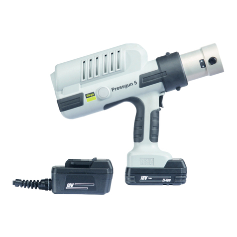
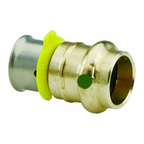
Fig. 2: Megapress press connectors
The system components are available in the following dimensions:
D ⅜ (DN 10), D ½(DN 15), D ¾(DN 20), D 1 (DN 25), D 1¼(DN 32),
D 1½(DN 40), D 2 (DN 50).
2.3.2 Pipes
Megapress press connectors may be used with the following seam-
less (S) or longitudinal welded (W) steel pipes:
nblack
ngalvanised
nindustrially painted
npowder coated
The steel pipes must correspond to the applicable regulations, see
Ä„Regulations from section: Pipes“ on page 6
If the pipe has been coated, the maximum external diameter
mentioned in the table must not be exceeded.
The standard differentiates between heavy pipe series H and medium
pipe series M or between pipe type L, L 1 and L 2. Seamless pipes and
pipes welded along the longitudinal seam belong to the different pipe
series and pipe types, see
Ä„Regulations from section: Pipes“
on page 6
.
Threaded pipe quality – heavy series H and Medium series M
Thread
size
[inch]
Nominal width
[DN]
Nominal
external diam-
eter [mm]
Min. external
diameter incl.
coating [mm]
Max. external
diameter incl.
coating [mm]
Wall thickness
heavy series H
[mm]
Wall thickness
medium series
M [mm]
⅜ 10 17.2 16.7 17.5 2.9 2.3
½15 21.3 21.0 21.8 3.2 2.6
Pipe overview – threaded pipe quality
Product information
Megapress 9 from 32

Thread
size
[inch]
Nominal width
[DN]
Nominal
external diam-
eter [mm]
Min. external
diameter incl.
coating [mm]
Max. external
diameter incl.
coating [mm]
Wall thickness
heavy series H
[mm]
Wall thickness
medium series
M [mm]
¾20 26.9 26.5 27.3 3.2 2.6
1 25 33.7 33.3 34.2 4.0 3.2
1¼32 42.4 42.0 42.9 4.0 3.2
1½40 48.3 47.9 48.8 4.0 3.2
2 50 60.3 59.7 60.8 4.5 3.6
Threaded pipe quality – pipe type L and pipe type L 1
Thread size
[inch]
Nominal width
[DN]
Nominal external
diameter [mm]
Min. external
diameter incl.
coating [mm]
Max. external
diameter incl.
coating [mm]
Wall thickness
[mm]
⅜ 10 17.2 16.7 17.4 2.0
½15 21.3 21.0 21.7 2.3
¾20 26.9 26.4 27.1 2.3
1 25 33.7 33.2 34.0 2.9
1¼32 42.4 41.9 42.7 2.9
1½40 48.3 47.8 48.6 2.9
2 50 60.3 59.6 60.7 3.2
Threaded pipe quality – pipe type L 2
Thread size
[inch]
Nominal width
[DN]
Nominal external
diameter [mm]
Min. external
diameter incl.
coating [mm]
Max. external
diameter incl.
coating [mm]
Wall thickness
[mm]
⅜ 10 17.2 16.7 17.1 1.8
½15 21.3 21.0 21.4 2.0
¾20 26.9 26.4 26.9 2.3
1 25 33.7 33.2 33.8 2.6
1¼32 42.4 41.9 42.5 2.6
1½40 48.3 47.8 48.4 2.9
2 50 60.3 59.6 60.2 2.9
Product information
Megapress 10 from 32

The standards differentiate between pipe series 1, 2 and 3. They recom-
mend using installation pipe series 1 as pipe series 2 and 3 are either
not or not always available in practice. Pipe series 1 includes seamless
pipes and pipes welded along the longitudinal seam, see
ĄRegula-
tions from section: Pipes“ on page 6
.
Boiler pipe quality – pipe series 1
Thread
size
[Inch]
Nominal
width
[DN]
Nominal
external
diameter
[mm]
Min.
external
diameter
incl. coating
[mm]
Max.
external
diameter
incl. coating
[mm]
Possible
pipe wall
thickness
for seam-
less pipes1)
[mm]
Possible pipe wall thick-
ness for pipes welded
along the longitudinal
seam1)
[mm]
⅜ 10 17.2 16.7 17.7 1.8–4.5 1.4–4.0
½15 21.3 20.8 21.8 2.0–5.0 1.4–4.5
¾20 26.9 26.4 27.4 2.0–8.0 1.4–5.0
1 25 33.7 33.2 34.2 2.3–8.8 1.4–8.0
1¼32 42.4 41.9 42.9 2.6–10.0 1.4–8.8
1½40 48.3 47.8 48.8 2.6–12.5 1.4–8.8
2 50 60.3 59.7 60.9 2.9–16.0 1.4–10.0
1) see
Ä„Regulations from section: Pipes“ on page 6
Only pipe clamps with chloride-free sound insulating inlays should be
used to secure the pipes.
Observe the general rules of fixing technology:
nDo not use fixed pipelines as a support for other pipelines and com-
ponents.
nDo not use pipe hooks.
nObserve the expansion direction: Plan fixed and gliding points.
Interval between the pipe clamps
D [mm] Nominal width
[inch]
Fixing interval
between
the pipe clamps
[m]
Fixing interval
between
the pipe clamps
[m]
17.2 ⅜ 2.25 —
21.3 ½2.75 —
1) see
Ä„Regulations from section: Pipes“ on page 6
Pipe overview – boiler pipe quality
Laying and fixing pipes
Product information
Megapress 11 from 32

D [mm] Nominal width
[inch]
Fixing interval
between
the pipe clamps
[m]
Fixing interval
between
the pipe clamps
[m]
26.9 ¾3.00 4.00
33.7 1 3.50 4.00
42.4 1 ¼3.75 4.00
48.3 1 ½4.25 4.00
60.3 2 4.75 4.00
1) see
Ä„Regulations from section: Pipes“ on page 6
Pipelines expand with heat. Heat expansion is dependent on the mate-
rial. Changes in length lead to tension within the installation. These ten-
sions must be equalised with suitable measures.
The following are effective:
nFixed and gliding points
nExpansion equalisation joints (expansion bends)
nCompensators
Heat expansion co-efficients of various pipe materials
Material Heat expansion co-effi-
cient ⍺
[mm/mK]
Example:
Length expansion with
pipe lengths L = 20 m
and ΔT = 50 K
[mm]
Steel 0.0120 12.0
Length expansion
Product information
Megapress 12 from 32

12
3
Fig. 3: Length expansion steel pipes
1 - Length expansion ΔI [mm]
2 - Pipe length l0[m]
3 - Temperature difference Δϑ [K]
The length expansion Δl can be taken from the diagram or can be cal-
culated using the following formula:
Δl =⍺[mm/mK]×L [m]xΔϑ [K]
2.3.3 Press connectors
Press connectors are available in a number of shapes. An overview of
the press connectors suitable for the system can be found in the cata-
logue.
Product information
Megapress 13 from 32

Fig. 4: Press connectors
The Megapress press connectors consist of non-alloy steel (mate-
rial 1.0308) and have an external high-quality 3–5 µm zinc-nickel
coating. There is a cutting ring, a separator ring and a profile sealing
element in the bead of the press connector. The cutting ring cuts into
the pipe during pressing and ensures a force-fit connection.
During installation, and later during the pressing, the separator ring pro-
tects the sealing element from damage from the cutting ring.
Fig. 5: SC-Contur
Viega press connectors are equipped with the SC-Contur. The SC-
Contur is a safety technology that is certified by the DVGW and ensures
that the connector is guaranteed to be leaky in an unpressed state. In
this way, inadvertently unpressed connections are noticed immediately
during a leakage test.
Viega guarantees that unpressed connections are visible during a
leakage test:
nwith the wet leakage test in the pressure range from 0.1–0,65 MPa
(1.0–6.5 bar)
nwith dry leakage test in the pressure range from 22 hPa–0.3 MPa
(22 mbar–3.0 bar)
SC-Contur
Product information
Megapress 14 from 32

2.3.4 Sealing elements
The press connectors are factory-fitted with EPDM profile sealing ele-
ments. The integrally moulded sealing lips also seal pipe surfaces with
slightly uneven surfaces.
Area of use Heating Solar installations Compressed air Technical gases
Use Pump hot water
heating system
Solar circuit all pipeline sections all pipeline sections
Operating tempera-
ture [Tmax.]110 °C 1) 60 °C —
Operating pressure
[Pmax]1.6 MPa (16 bar) 0.6 MPa (6 bar) 1.6 MPa (16 bar) —
Comments Tmax 105 °C2)
with radiator con-
nections Tmax: 95 °C
for flat collectors dry, oil content
< 25 mg / m31)
1) Consultation with the Viega Service Center required
2) see
Ä„Regulations from section: Sealing elements“ on page 6
2.3.5 Markings on components
The press connectors are marked with a coloured dot. This identifies
the SC-Contur, where the test medium would escape in the case of an
inadvertently unpressed connection.
The black dot indicates that the system is not suitable for drinking water
and is equipped with the SC-Contur.
The black rectangle serves as a warning
"Not suitable for drinking
water!"
.
The rectangle is to be found in the following places:
non the press end of the press connector
non the flange of the flange adapter
Area of use of the EPDM sealing element
Markings on press connectors
Product information
Megapress 15 from 32

Fig. 6: Black dot and inscription "Not suitable for drinking water"
Fig. 7: Inscription "Not suitable for drinking water"
2.4 Information for use
2.4.1 Corrosion
A zinc-nickel coating protects Megapress press connectors against
external corrosion, e. g. in the case of arising condensation water in
cooling systems.
Pipes must be equipped with suitable corrosion protection.
Observe the manufacturer's information.
Product information
Megapress 16 from 32

3 Handling
3.1 Transport
Observe the following when transporting pipes:
nDo not pull the pipes over the sill. The surface could be damaged.
nSecure pipes during transportation. Pipes may become bent due to
shifting.
nDo not damage the protective caps on the pipe ends and do not
remove them until immediately before mounting. Damaged pipe
ends may not be pressed.
In addition, observe the instructions provided by the pipe
manufacturer.
3.2 Storage
For storage, comply with the requirements specified in the applicable
regulations, see
Ä„Regulations from section: Storage“ on page 7
:
nStore components in a clean and dry place.
nDo not store the components directly on the floor.
nProvide at least three points of support for the storage of pipes.
nWhere possible, store different sizes separately.
Store small sizes on top of larger sizes if separate storage is not pos-
sible.
nTo prevent contact corrosion, store pipes of different materials sepa-
rately.
In addition, observe the instructions provided by the pipe
manufacturer.
3.3 Assembly information
3.3.1 Mounting instructions
System components may, in some cases, become damaged through
transportation and storage.
nCheck all parts.
nReplace damaged components.
nDo not repair damaged components.
nContaminated components may not be installed.
Checking system components
Handling
Megapress 17 from 32

The following requirements must be observed:
nFor the applicable directives, see
ĄRegulations from section:
Notes on mounting“ on page 7
nObservation of the data from the following table
For sprinkler systems in compliance with VdS, only black,
galvanised, or powder-coated steel pipes according to the
specifications for VdS approval may be used.
For nominal widths up to and including DN 50, the minimum
pipe wall thickness of 2.6 mm and the maximum wall thick-
ness of 3.3 mm are applicable. For the distances and
arrangement (fixing intervals) for steel pipes according to
current regulations, see ĄRegulations from section: Notes
on mounting“ on page 7.
Permissible pressures, nominal widths and application conditions
Permitted pressure 1.6 MPa (16 bar)
Nominal widths D ¾–2
Pipe wall thickness min. 2.6 mm; max 3.3 mm
Area of use (piping network) Wet sprinkler units:
nPiping network downstream of
the alarm valve station
Dry sprinkler units:
nPiping network downstream of
the alarm valve station
Fixing intervals 1)
Firefighting water additives Generally not permitted; excep-
tions only with the manufacturer's
permission and prior agreement
of the VdS
1) see
Ä„Regulations from section: Notes on mounting“ on page 7
The following fire hazard classes are covered by Megapress:
nFire hazard class LH (light hazard)
nFire hazard class OH 1–4 (ordinary hazard)
nFire hazard class HHP 1–4 (extra hazard, production risks)
nFire hazard class HHS 1–4 (extra hazard, storage risks)
As long as they are free from dirt, smooth, firm, even and undamaged,
the following pipe surfaces are suitable for the production of press con-
nections without further treatment:
Fire extinguisher and sprinkler systems
Preparation of the pipes
Handling
Megapress 18 from 32

black, not coated
galvanised (maximum external diameter in acc. with
ÄChapter 2.3.2
„Pipes“ on page 9
)
industrially painted or powder-coated (maximum external diameter in
acc. with
ÄChapter 2.3.2 „Pipes“ on page 9
)
Pipe surfaces must be treated around the press connection if they
exhibit the following characteristics:
Handling
Megapress 19 from 32

uneven, manually applied layers of paint
Exceeding the maximum external diameter due to coating that has been
added
ÄChapter 2.3.2 „Pipes“ on page 9
Bumps, damage, grooves, corrosion or loose adhesions
The following are examples of suitable tools for the work:
Wire brush
Handling
Megapress 20 from 32
Other manuals for Megapress
1
Table of contents
Other Viega Tools manuals

Viega
Viega Pressgun Picco 6 Plus User manual

Viega
Viega MegaPress Z3 Actuator User manual

Viega
Viega Pressgun Picco User manual

Viega
Viega PureFlow Instruction sheet

Viega
Viega PureFlow 50030 Instruction sheet

Viega
Viega Pressgun 5 User manual

Viega
Viega 2489.1 User manual

Viega
Viega 6 PlusPress User manual

Viega
Viega 50000 Instruction sheet

Viega
Viega Smartpress User manual