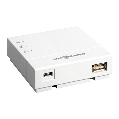
Viessmann VITOCONNECT 100 Operating instructions

Installation and service instructions
for contractors
VIESMANN
Vitoconnect 100
Type OPTO1
Communication interface for remote monitoring and control of heating systems via
the internet, for the following user interfaces:
■ViCare app
■Vitotrol Plus app
■Vitoguide
For applicability, see the last page
VITOCONNECT 100
5785 665 GB 9/2016 Please keep safe.

2
Please follow these safety instructions closely to
prevent accidents and material losses.
Safety instructions explained
Danger
This symbol warns against the risk of injury.
!Please note
This symbol warns against the risk of material
losses and environmental pollution.
Note
Details identified by the word "Note" contain additional
information.
Target group
These instructions are exclusively intended for author-
ised contractors.
■Work on electrical equipment must only be carried
out by a qualified electrician.
■The system must be commissioned by the system
installer or a qualified person authorised by the
installer.
Regulations to be observed
■National installation regulations
■Statutory regulations for the prevention of accidents
■Statutory regulations for environmental protection
■Codes of practice of the relevant trade associations
■All relevant safety regulations as defined by DIN, EN,
DVGW, VDE and locally applicable standards
aÖNORM, EN and ÖVE
cSEV, SUVA, SVTI and SWKI
Safety instructions for working on the system
Working on the system
■Isolate the system from the power supply (e.g. by
removing the separate fuse or by means of a mains
isolator) and check that it is no longer 'live'.
■Safeguard the system against reconnection.
Danger
Hot surfaces can cause burns.
■Before maintenance and service work, switch
OFF the appliance and let it cool down.
■Never touch hot surfaces on the boiler, burner,
flue system or pipework.
!Please note
Electronic assemblies can be damaged by elec-
trostatic discharge.
Prior to commencing work, touch earthed
objects such as heating or water pipes, to dis-
charge static loads.
Repair work
!Please note
Repairing components that fulfil a safety func-
tion can compromise the safe operation of the
system.
Replace faulty components only with genuine
Viessmann spare parts.
Auxiliary components, spare and wearing parts
!Please note
Spare and wearing parts that have not been tes-
ted together with the system can compromise its
function. Installing non-authorised components
and making non-approved modifications or con-
versions can compromise safety and may inva-
lidate our warranty.
For replacements, use only original spare parts
supplied or approved by Viessmann.
Safety instructions for operating the system
If you smell flue gas
Danger
Flue gas can lead to life threatening poisoning.
■Shut down the heating system.
■Ventilate the installation site.
■Close doors to living spaces to prevent flue
gases from spreading.
What to do if water escapes from the appliance
Danger
When water escapes from the appliance there is
a risk of electrocution.
Switch off the heating system by means of an
external isolator (for example fuse box, domestic
power distribution).
Flue systems and combustion air
Ensure that flue systems are clear and cannot be
sealed, for instance due to accumulation of conden-
sate or other causes. Ensure an adequate supply of
combustion air.
Instruct system users that subsequent modifications to
the building characteristics are not permissible (e.g.
cable/pipework routing, cladding or partitions).
Danger
Leaking or blocked flue systems, or an inade-
quate supply of combustion air can cause life
threatening poisoning from carbon monoxide in
the flue gas.
Ensure the flue system is in good working order.
Vents for supplying combustion air must be non-
closable.
Safety instructions
Safety instructions
5785 665 GB

3
Extractors
Operating appliances that extract air to the outside
(cooker hoods, extractors, air conditioning units, etc.)
can create negative pressure. If the boiler is operated
at the same time, this can lead to reverse flow of the
flue gas.
Danger
The simultaneous operation of the boiler and
appliances that extract air to the outside can
result in life threatening poisoning due to
reverse flow of the flue gas.
Fit an interlock circuit or take suitable steps to
ensure an adequate supply of combustion air.
Safety instructions
Safety instructions (cont.)
5785 665 GB

4
1. Safety and liability Operational reliability ............................................................................. 5
Liability ................................................................................................... 5
2. Information Symbols ................................................................................................. 6
Intended use .......................................................................................... 6
3. Preparing for installation System requirements ............................................................................. 7
■Heating system ................................................................................... 7
■Supported control units ....................................................................... 7
■IP network ........................................................................................... 7
Operation via app .................................................................................. 8
■Functions ............................................................................................ 8
4. Installation sequence Sequence overview ............................................................................... 10
Installation location ................................................................................ 10
■Range ................................................................................................. 10
Installing the wall mounting bracket ....................................................... 11
5. Electrical connections ................................................................................................................ 12
6. Commissioning Display and controls .............................................................................. 13
■Interpreting the LED indicators ........................................................... 13
Checking the network settings ............................................................... 14
Registering the user and setting up the heating system ........................ 14
■With ViCare app .................................................................................. 14
■With Vitotrol Plus app ......................................................................... 15
7. Troubleshooting Troubleshooting measures .................................................................... 16
Maintenance mode ................................................................................ 17
Resetting the network settings ............................................................... 17
Restoring the factory setting .................................................................. 17
8. Parts lists Ordering parts ........................................................................................ 19
EU: Parts list .......................................................................................... 20
GB/US/CA: Parts list .............................................................................. 22
9. Specification ................................................................................................................ 24
10. Keyword index ................................................................................................................ 25
Index
Index
5785 665 GB

5
The Vitoconnect 100 enables communication via the
internet between the connected Vitotronic control unit
and the Viessmann server.
The full range of functions is only available if the fol-
lowing conditions are met:
■The Vitotronic control units and the Vitoconnect 100
must be connected and configured correctly.
■The Vitoconnect 100 is connected to the internet via
a WLAN router.
■Internet access must be available at all times.
■The user has been registered (see page 14).
■To ensure that messages can still be sent if there is a
power failure, we recommend connecting the
Vitoconnect 100 and WLAN router to the power sup-
ply via a UPS.
Note
■The heating system and the functionality of the mes-
sage paths must be tested at regular intervals.
■To further improve the operational reliability of the
heating system, we recommend implementing sup-
plementary measures, e.g. frost protection or moni-
toring for water damage.
Liability
Viessmann accepts no liability for loss of profit, unat-
tained savings, or other direct or indirect consequential
losses resulting from use of the Vitoconnect 100, the
Viessmann server or the software, or for damage
resulting from inappropriate use.
The Viessmann General Terms and Conditions apply,
which are included in each current Viessmann pricelist.
Viessmann accepts no liability for SMS via push notifi-
cation and email services, which are provided by net-
work operators. The terms and conditions of the rele-
vant network operators apply in this context.
Safety and liability
Operational reliability
5785 665 GB
Information

6
Symbol Meaning
Reference to other document containing
further information
1.
Step in a diagram:
The numbers correspond to the order in
which the steps are carried out.
Warning of material losses and environ-
mental pollution
Live electrical area
Pay particular attention.
■Component must audibly click into place.
or
■Acoustic signal
■Fit new component.
or
■In conjunction with a tool: Clean the sur-
face.
Dispose of component correctly.
Dispose of component at a suitable collec-
tion point. Do not dispose of component in
domestic waste.
Intended use
Install and operate Vitoconnect products as intended,
in conjunction with the electronic control units and con-
trollers for the Viessmann heat and power generators
designed for this system. In particular, observe the cur-
rent and voltage specifications for connections and
hook-ups.
Use Vitoconnect products exclusively for remotely
operating and optimising systems, in conjunction with
the user and communication interfaces specified for
this purpose in the relevant printed documentation.
With regard to the communication interfaces, ensure
on site that the system requirements specified in the
product documentation are met at all times for every
transfer medium employed. For this, only use the
approved communication components supplied with
the products. Only use the specified components for
the mains power supply (e.g. power supply units).
Information
Symbols
5785 665 GB
Information

7
Heating system
The Vitoconnect 100, type OPTO1 can be used for a
single boiler system with Vitotronic control unit, without
heating circuits downstream.
Supported control units
The Vitoconnect 100, type OPTO1, can be used in
conjunction with the following Viessmann control units.
Heat source
Wall mounted or storage
combi boilers
Floorstanding boilers Heat pumps and hybrid
appliances
Solid fuel boilers
Supported control units
Vitotronic 200, type
■HO1
■HO1A
■HO1B
■HO1D
■HO2B
Vitotronic 200-RF, type
■HO1C
■HO1E
Vitotronic 200, type
■KO1B
■KO2B
■KW1
■KW2
■KW4
■KW5
■KW6
■KW6A
■KW6B
Vitotronic 300, type
■KW3
See www.viessmann.com/vitoconnect
Note
For an up to date overview of the supported control
units see www.viessmann.com/vitoconnect.
IP network
System requirements
■WLAN router with activated WLAN. The WLAN
router of the system user must be protected by a suf-
ficiently secure WPA2 password. We advise against
unencrypted connection of the Vitoconnect 100 to a
WLAN router.
■Internet connection with "flat rate" (tariff independ-
ent of time and data volume) and high availability,
i.e. the Vitoconnect 100 is permanently linked to the
Viessmann server.
■Have dynamic IP addressing (DHCP, factory setting)
on the network (WLAN) checked on site, and if
required set up, by an IT expert prior to commis-
sioning.
■Determine the routing and security parameters in the
IP network (LAN) as follows: Enable Port 80 and
Port 443 for direct outward connections. Have this
checked and, if necessary, set up on site by an IT
expert before commissioning.
Note
During operation, the Vitoconnect 100 establishes a
secure internet connection to the Viessmann server.
Connecting the Vitoconnect 100 to any other type of
server is not possible.
User account
A valid user account on the Viessmann server is
required for the operation of the Vitoconnect 100,
regardless of which control device is used. Registra-
tion for this occurs automatically during commission-
ing, either via the ViCare app or via the
Vitotrol Plus app (see page 14).
Control device for the ViCare app
Smartphone or tablet PC with the following operating
systems:
■Apple iOS, version 8 or higher
or
■Google Android, version 4.4 or higher
Preparing for installation
System requirements
5785 665 GB
Installation

8
Control device for the Vitotrol Plus app
Smartphone or tablet PC with the following operating
systems:
■Apple iOS, version 8 or higher
or
■Google Android, version 4.4 or higher
Message destinations
Terminal device for receiving email, e.g. a computer,
smartphone or tablet.
Operation via app
For remote control of Viessmann heating systems with Vitotronic control units via IP network.
K
BC
A
E
D
H
G
F
Fig. 1
AHeat source with control unit
BConnecting lead Optolink/USB
CVitoconnect 100
DWLAN
EWLAN router (on site)
FSecure internet connection to the Viessmann
server
GViessmann server
HMobile network
or
WLAN connection
KWeb-enabled control device
Functions
ViCare app operating functions
■Display of system status for system user
■Easy to use remote operating function, e.g. adjusting
the set room temperature or operating mode
■Modification of heating periods via switching time
assistant
■Quick selection keys for party mode and setback
mode ("Extended heating" and "Away")
■Reporting of faults by push notification
■Automatically stored contact details for heating con-
tractor
■Description of fault in plain text
■Operating data of the system can be integrated in
Vitoguide for contractors
■Easy transmission of system data, e.g. fault mes-
sages via email or telephone communication with the
heating contractor
■Energy saving tips
Note
■The ViCare app enables users to access only one
system at a time using an terminal device.
■For further information on the ViCare app see
www.vicare.info
Vitotrol Plus app operating functions
■Remote control of all heating circuits in a heating
system
■Setting of operating programs, set values and time
programs (central heating and DHW heating)
■Calling up system information
■Message display in plain text
■Automatic forwarding of messages via email
■Consumption data display
■Integral showcase function
Note
For further information on the Vitotrol Plus app see
www.vitotrol.info
Preparing for installation
System requirements (cont.)
5785 665 GB
Installation

9
Forwarding messages
Any pending messages from the heating system, e.g.
sensor or burner faults, are transmitted to the
Vitoconnect 100 via Optolink and USB. The
Vitoconnect 100 transmits these messages to the
Viessmann server. The ViCare app and
Vitotrol Plus app regularly check the heating system
status and display any messages.
Note
Heating system messages are only displayed if the
ViCare app or Vitotrol Plus app is enabled on the
mobile terminal device.
Content of messages
■Message type
■Message code
■Message text
Heat source installation and service instructions
Preparing for installation
Operation via app (cont.)
5785 665 GB
Installation

10
Sequence Responsibility Page
Installation
1 Check system requirements. Heating contractor/IT expert 7
2 Fit wall mounting bracket for Vitoconnect 100. Heating contractor 11
3 Connect Vitoconnect 100 to heat source. Heating contractor 12
4 Insert Vitoconnect 100 into wall mounting bracket. Heating contractor 11
5 Connect power supply. Heating contractor 12
Commissioning
6 Check network settings. IT expert 14
7 Register user and set up heating system. Heating contractor/system user 14
■Operation with ViCare app
■Operation with Vitotrol Plus app
Installation location
A
>0.3 m
Fig. 2 Sample illustration with wall mounted boiler
ATo ensure a good WLAN connection, keep the dis-
tance between the Vitoconnect 100 and the WLAN
router as short as possible.
Installation type: wall mounting
■Distance to heat source: minimum 0.3 m
■Standard socket 230 V/50 Hz, max. 1 m lateral dis-
tance to installation site
■Internet access with adequate WLAN signal
Note
The WLAN signal strength can be increased with
commercially available WLAN repeaters.
Note
When selecting the installation site, bear in mind the
length of the connecting cables (standard delivery).
Connecting cables/leads Length
Connecting lead Optolink/USB for con-
necting the Vitoconnect 100 to the boiler
control unit
3 m
Plug-in power supply unit with power ca-
ble
1 m
Range
The range of WLAN connections may be reduced by
walls, ceilings and interior fixtures. These weaken the
WLAN signal and can cause poor reception.
Installation sequence
Sequence overview
5785 665 GB
Installation

11
Range reduction:
■On their way between transmitter and receiver,
WLAN signals are damped, e.g. by air or when pen-
etrating walls.
■WLAN signals are reflected by metallic objects e.g.
reinforcements in walls, metal foil of thermal insula-
tion and thermal glazing with metallised thermal
vapour deposit.
■WLAN signals are isolated by service ducts and lift
shafts.
■WLAN signals suffer interference from appliances
that also operate with high frequency signals,
such as computers, audio and video systems, wire-
less signals, electrical transformers and pre-ballast.
Distance to such appliances: minimum 2 m.
Installing the wall mounting bracket
Installation only in enclosed buildings. !Please note
The installation site must be dry and free from
the risk of frost.
Ensure ambient temperatures between −5 and
40 °C.
1.
3.
2.
Fig. 3
Installation sequence
Installation location (cont.)
5785 665 GB
Installation

12
At the Vitoconnect 100, view from below At the control unit of the heat source
A B
AMicro USB for power supply from plug-in power
supply unit
BFor connecting lead Optolink/USB
A
AFor connecting lead Optolink/USB
1. Connect the Vitoconnect 100 to the heat source
using the Optolink/USB connecting lead.
Cable routing in the heat source:
Heat source documentation
2. Insert the plug-in power supply unit with power
cable into the standard socket.
Electrical connections
5785 665 GB
Installation

13
A
1
2
3
Fig. 4
AReset button
1LED indicates status of communication with heat
source.
2LED indicates status of communication with
WLAN and Viessmann server.
3LED indicates system functions (access point
mode, offline mode, update, fault).
Interpreting the LED indicators
LED – Communication with the heat source
Flashes yellow. Connection between Vitoconnect 100 and heat source being established
Illuminates green. Connection between Vitoconnect 100 and heat source successfully established
Flashes red. No connection to the heat source, see page 16.
LED – Communication with the Viessmann server
Flashes yellow. Connection between Vitoconnect 100 and WLAN router being established
Illuminates yellow. Connection between Vitoconnect 100 and WLAN router successfully established
Flashes green. Connection between Vitoconnect 100 and Viessmann server being established
Illuminates green. Connection between Vitoconnect 100 and Viessmann server successfully establish-
ed
Flashes red. No connection to the internet, see page 16.
Commissioning
Display and controls
5785 665 GB
Commissioning

14
LED – System functions
Flashes yellow. Maintenance mode (no data transfer), see page 17
Pulsates yellow. Registration mode active (access point)
Flashes red. Fault at the control unit of the heat source
Pulsates red. Access point mode fault, see page 16
Flashes green. A new Vitoconnect 100 firmware is being installed.
!Please note
Take care not to damage the Vitoconnect.
Never disconnect the Vitoconnect 100 from the power supply during firmware
installation.
LED , and
All are illuminated white. The Vitoconnect 100 starts.
All are illuminated yellow. The Vitoconnect 100 has been reset to the factory setting and can be commissioned
again.
Note
Flashing: LED 0.5 s on and 0.5 s off
Pulsating: LED 0.1 s on and 0.9 s off
Checking the network settings
Have the following settings on the WLAN router
checked, and if necessary adjusted, by an IT expert:
■Dynamic IP addressing must be set.
■Port 80 and port 443 must be enabled for outgoing
connections.
Registering the user and setting up the heating system
With ViCare app
1. Download and install the ViCare app from the App
Store or Play Store.
Note
If an Apple iPad is being used, limit the app search
to "iPhone only".
2. Start the ViCare app and tap on "Create new
account".
3. Scan the QR code or enter the "manufacturing
data" and "ID".
Note
For the QR code, "manufacturing data" and "ID"
see the label on the Vitoconnect 100.
Vitoconnect 100 OPTO1
Manufacturing data
ID:
MAC addr.:
WPA2:
www.viessmann.com/vitoconnect
Fig. 5
4. Set up the WLAN
Android: Connection is automatically established
with WLAN "Vitoconnect"
iOS: ■Close the ViCare app an call up the
WLAN settings of the smartphone.
■Connect the "Vitoconnect" via WLAN.
■Insert WPA2 password from the clip-
board. The WPA2 password is auto-
matically placed on the clipboard. If
not, see the label on the Vitoconnect.
■Switch back to the ViCare app.
5. Follow the instructions in the app.
■Set up the home network.
■Enter location or allow ViCare app access to the
location.
■Enter personal data.
■Accept the data protection agreement and terms
of use.
The Vitoconnect 100 and ViCare app are set up.
Commissioning
Display and controls (cont.)
5785 665 GB
Commissioning

15
With Vitotrol Plus app
1. Download and install the Vitotrol Plus app from the
App Store or Play Store.
2. Start up the Vitotrol Plus app and tap on "Create
access".
3. Enter personal data.
4. When asked "Configure Vitoconnect 100" select
yes.
5. Scan the QR code or enter the "manufacturing
data" and "ID".
Note
For the QR code, "manufacturing data" and "ID"
see the label on the Vitoconnect 100.
Vitoconnect 100 OPTO1
Manufacturing data
ID:
MAC addr.:
WPA2:
www.viessmann.com/vitoconnect
Fig. 6
6. Set up the WLAN
Android: Connection is automatically established
with WLAN "Vitoconnect"
iOS: ■In the Vitotrol Plus app, tap on
"WLAN settings". The WLAN set-
tings of the smartphone are called up.
■Connect the "Vitoconnect" via WLAN.
■Insert WPA2 password from the clip-
board. The WPA2 password is auto-
matically placed on the clipboard. If
not, see the label on the Vitoconnect.
■Switch back to the Vitotrol Plus app.
7. Follow the instructions in the app.
■Set up the home network.
■Enter the system name and location.
■Accept the data protection agreement and terms
of use.
The Vitoconnect 100 and the Vitotrol Plus app are
set up.
Commissioning
Registering the user and setting up the heating… (cont.)
5785 665 GB
Commissioning

16
Faults on the Vitoconnect 100 are signalled by various
LED indicators (see page 13).
Faults with LED indication
Type of fault and measures
LED
Flashes red. No connection to the heat source
■Check the plug-in connections (Optolink, USB).
■Check the connecting lead.
LED
Flashes red. No connection to the internet
■No WLAN connection
–Check the network settings during WLAN commissioning.
–Check the password during WLAN commissioning.
■WLAN signal strength insufficient
–Change the installation location of the Vitoconnect 100, see page 10
■WLAN connection established, but no internet connection
–Check the internet connection with another subscriber, e.g. a laptop.
If no internet connection is possible even with another subscriber, have the
network settings checked by an IT expert.
LED and LED
LED flashes red
LED pulsates yellow
No connection to the internet
WLAN password of the home network is incorrect. Repeat entry.
LED
Flashes red. Fault at the control unit of the heat source
■Observe the message in the ViCare app or Vitotrol Plus app.
Heat source installation and service instructions
Pulsates red. Access point mode fault
■Reset the network settings, see page 17
Flashes yellow. Maintenance mode (no data transfer)
■Deactivate maintenance mode, see page 17
Flashes green. A new Vitoconnect 100 firmware is being installed.
!Please note
Take care not to damage the Vitoconnect 100.
Never disconnect the Vitoconnect 100 from the power supply during
firmware installation.
Faults without LED indicator
Fault Steps
All indicators on the
Vitoconnect 100 are off.
Check the power supply and plug-in power supply unit of the Vitoconnect 100.
Troubleshooting
Troubleshooting measures
5785 665 GB
Diagnosis

17
With this function, the transfer of messages from the
heating system to the Viessmann server is sup-
pressed, e.g. during maintenance work on the heating
system.
Activation
Press the reset button for approx. 2 s. LED flashes
yellow.
Maintenance mode is activated.
Note
Maintenance mode is not terminated automatically and
must be deactivated.
Deactivation
Press the reset button for approx. 2 s. LED is no
longer illuminated.
Maintenance mode is deactivated.
Resetting the network settings
1. Press the reset button for 5 s, until LED pul-
sates yellow.
2. Connect the smartphone with the internal WLAN of
the Vitoconnect 100. For WLAN-SSID and WPA2
password see the label on the Vitoconnect.
3. Open the internet browser on the smartphone and
enter the address http://vitoconnect.gateway.
Follow the instructions on the website.
Restoring the factory setting
1. Press the reset button for longer than 30 s, until all
3 LEDs are flashing yellow.
2. Release the reset button.
3. Press the reset button again, this time for longer
than 5 s, until all LEDs are illuminated yellow.
4. Release the reset button.
The Vitoconnect 100 is back to its factory setting.
Troubleshooting
Maintenance mode
5785 665 GB
Diagnosis

18
Troubleshooting
Restoring the factory setting (cont.)
5785 665 GB
Diagnosis

19
The following details are required when ordering parts:
■Order no. (see type plate A)
■Position number of the part (from this parts list)
A
Fig. 7
Parts lists
Ordering parts
5785 665 GB
Components

20
0001 0002
Fig. 8
Parts lists
EU: Parts list
5785 665 GB
Components
Other manuals for VITOCONNECT 100
2
This manual suits for next models
1
Table of contents
Other Viessmann Conference System manuals