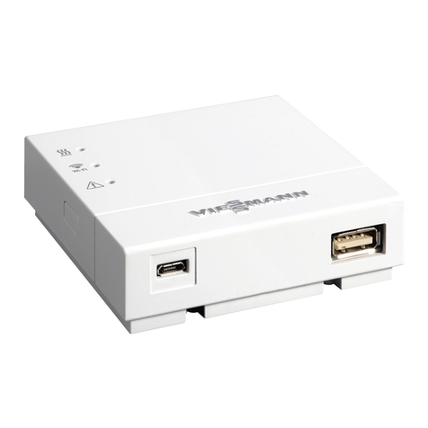
Viessmann Vitogate 200 Operating instructions

Installation and service instructions
for contractors
VIESMANN
Vitogate 200
Type KNX
Communication for heating systems via KNX/EIB systems
VITOGATE 200
5673180 GB 5/2019 Please keep safe.

2
Please follow these safety instructions closely to
prevent accidents and material losses.
Safety instructions explained
Danger
This symbol warns against the risk of injury.
!Please note
This symbol warns against the risk of material
losses and environmental pollution.
Note
Details identified by the word "Note" contain additional
information.
Target group
These instructions are exclusively intended for author-
ised contractors.
■Work on electrical equipment must only be carried
out by a qualified electrician.
■The system must be commissioned by the system
installer or a qualified person authorised by the
installer.
Regulations to be observed
■National installation regulations
■Statutory regulations for the prevention of accidents
■Statutory regulations for environmental protection
■Codes of practice of the relevant trade associations
■Relevant country-specific safety regulations
Safety instructions for working on the system
Working on the system
■Isolate the system from the power supply (e.g. by
removing the separate fuse or by means of a mains
isolator) and check that it is no longer 'live'.
■Safeguard the system against reconnection.
Danger
Hot surfaces can cause burns.
■Before maintenance and service work, switch
OFF the appliance and let it cool down.
■Never touch hot surfaces on the boiler, burner,
flue system or pipework.
!Please note
Electronic assemblies can be damaged by elec-
trostatic discharge.
Prior to commencing work, touch earthed
objects such as heating or water pipes, to dis-
charge static loads.
Repair work
!Please note
Repairing components that fulfil a safety func-
tion can compromise the safe operation of the
system.
Replace faulty components only with genuine
Viessmann spare parts.
Auxiliary components, spare and wearing parts
!Please note
Spare and wearing parts that have not been tes-
ted together with the system can compromise its
function. Installing non-authorised components
and making non-approved modifications or con-
versions can compromise safety and may inva-
lidate our warranty.
For replacements, use only original spare parts
supplied or approved by Viessmann.
Safety instructions
Safety instructions
5673180

3
Safety instructions for operating the system
If you smell flue gas
Danger
Flue gas can lead to life threatening poisoning.
■Shut down the heating system.
■Ventilate the installation site.
■Close doors to living spaces to prevent flue
gases from spreading.
What to do if water escapes from the appliance
Danger
When water escapes from the appliance there is
a risk of electrocution.
Switch off the heating system by means of an
external isolator (for example fuse box, domestic
power distribution).
Flue systems and combustion air
Ensure that flue systems are clear and cannot be
sealed, for instance due to accumulation of conden-
sate or other causes. Ensure an adequate supply of
combustion air.
Instruct system users that subsequent modifications to
the building characteristics are not permissible (e.g.
cable/pipework routing, cladding or partitions).
Danger
Leaking or blocked flue systems, or an inade-
quate supply of combustion air can cause life
threatening poisoning from carbon monoxide in
the flue gas.
Ensure the flue system is in good working order.
Vents for supplying combustion air must be non-
closable.
Extractors
Operating appliances that extract air to the outside
(cooker hoods, extractors, air conditioning units, etc.)
can create negative pressure. If the boiler is operated
at the same time, this can lead to reverse flow of the
flue gas.
Danger
The simultaneous operation of the boiler and
appliances that extract air to the outside can
result in life threatening poisoning due to
reverse flow of the flue gas.
Fit an interlock circuit or take suitable steps to
ensure an adequate supply of combustion air.
Safety instructions
Safety instructions (cont.)
5673180

4
1. Information Disposal of packaging ............................................................................ 5
Symbols ................................................................................................. 5
Intended use .......................................................................................... 5
Protection against unauthorised access ................................................ 6
Product information ................................................................................ 6
Functions ............................................................................................... 6
Spare parts lists ..................................................................................... 6
2. Installation sequence Installing the Vitogate 200, type KNX .................................................... 7
■Removing the cover ............................................................................ 8
Overview of connections ........................................................................ 8
Connecting the Vitogate 200, type KNX ................................................ 9
Connecting the power supply ................................................................ 10
Applying strain relief to all cables .......................................................... 10
Closing the wiring chamber ................................................................... 10
3. Commissioning Display and operating elements ............................................................ 11
■With cover ........................................................................................... 11
■Without cover ...................................................................................... 11
Commissioning ...................................................................................... 12
Integrating the Vitotronic control unit into LON ...................................... 12
■Viessmann system number and subscriber number ........................... 13
■Checking the LON connection to the Vitotronic control unit ............... 13
Product database ................................................................................... 14
■Product database ............................................................................... 14
■Device data for the system integrator ................................................. 14
4. Troubleshooting LON connection error ............................................................................ 15
Restoring the factory settings ................................................................ 15
5. Specification Vitogate 200, type KNX ......................................................................... 16
Plug-in power supply unit ....................................................................... 16
6. Certificates Declaration of conformity ....................................................................... 17
7. Keyword index ................................................................................................................ 18
Index
Index
5673180

5
Please dispose of packaging waste in line with statu-
tory regulations.
Symbols
Symbol Meaning
Reference to other document containing
further information
1.
Step in a diagram:
The numbers correspond to the order in
which the steps are carried out.
Warning of material losses and environ-
mental pollution
Live electrical area
Pay particular attention.
■Component must audibly click into place.
or
■Acoustic signal
■Fit new component.
or
■In conjunction with a tool: Clean the sur-
face.
Dispose of component correctly.
Dispose of component at a suitable collec-
tion point. Do not dispose of component in
domestic waste.
Intended use
The Vitogate product is intended to be installed and
operated only in conjunction with Vitotronic control
units, with due attention paid to the associated installa-
tion, service and operating instructions. The Vitogate
may only be used in systems with supported
Viessmann heat and power generators.
The Vitogate can only be used with the user and com-
munication interfaces defined in the product documen-
tation for the following purposes:
■To monitor systems
■To operate systems
■To optimise systems
With regard to the communication interfaces, ensure
on site that the system requirements specified in the
product documentation are met at all times for every
transfer medium employed. Only use the specified
components for the power supply (e.g. power supply
units).
Intended use presupposes that a fixed installation in
conjunction with permissible, system-specific compo-
nents has been carried out.
Information
Disposal of packaging
5673180
Information

6
Commercial or industrial use for a purpose other than
the monitoring, operation and optimisation of suppor-
ted, approved systems shall be deemed inappropriate.
Protection against unauthorised access
Protection of the KNX TP against unauthorised
access by third parties
The Vitogate cable must not be routed outside a build-
ing.
Ensure that no unauthorised persons have access to
the Vitogate cable, so that the Vitogate control unit and
the heating system cannot be sabotaged.
Protection of KNXnet/IP (tunnelling) against unau-
thorised access by third parties
KNXnet/IP (tunnelling), which can be reached via UDP
port 3761, has no access protection and must there-
fore always be operated within specially protected net-
works. In particular, UDP port 3761 must not be made
openly accessible from the internet on the router. If you
want to access the Vitogate via the internet, take
appropriate measures to protect KNXnet/IP (tunnel-
ling). To do this, set up VPN access, for example.
If this point is not observed, third parties can take con-
trol of and sabotage the Vitogate and the heating sys-
tem via the internet.
Protection of the LON against unauthorised access
by third parties
Tunnelling the LON over IP networks is in principle
technically possible with corresponding commercially
available LON routers. However, this configuration is
not supported and must not be used.
Product information
The following appliances are hooked up to KNX/EIB
systems with the Vitogate 200, type KNX gateway:
■Vitotronic control units with integral LON communica-
tion module (accessory)
The Vitogate 200, type KNX must be integrated into
the KNX/EIB system by an authorised contractor.
Functions
The Vitogate 200, type KNX enables system users to
utilise the following functions in conjunction with a
KNX/EIB system:
■Transferring heating system operating states
■Specifying set values
■Relaying fault and error messages
■Heat demand-dependent control of the flow tempera-
ture in conjunction with constant KNX/EIB control of
individual room temperature
Spare parts lists
Information about spare parts can be found on the
Viessmann spare parts app.
Information
Intended use (cont.)
5673180
Information

7
!Please note
Unfavourable ambient conditions can lead to
malfunctions and appliance damage.
■The installation location must be dry and free
from the risk of frost.
■Ensure ambient temperatures between 0 and
40 °C.
Note
When selecting the installation location, bear in mind
the length of the connecting cables in the standard
delivery.
Connecting cables Length
KNX TP connecting cable (on site)
Recommended cable:
KNX TP YCYM 2 x 2 x 0.8 mm2
■In a line:
Max. 1000 m
■Between a power supply and the last subscriber:
Max. 350 m
■Between 2 subscribers and a line:
Max. 700 m
■Between 2 power supplies:
Min. 200 m
Ethernet connecting cable (KNXnet/IP, on site) —
LON cable (standard delivery) 7 m
Extension of the LON cable:
Possible with accessories; see communication module
installation instructions
Max. 900 m
Connecting cable for plug-in power supply unit (stand-
ard delivery)
Approx. 2.0 m
2.
1.
3.
Fig. 1
Installation sequence
Installing the Vitogate 200, type KNX
5673180
Installation

8
Removing the cover
Fig. 2
!Please note
When the power supply is connected, touching
electrical contacts can result in appliance dam-
age.
Always unplug the power supply unit before
removing the cover.
Overview of connections
A
Fig. 3
"1" Plug-in power supply unit connection, 5 V–, inter-
nal "–", external "+", min. 0.4 A
"3" Service interface: Never make any on-site con-
nections
"4" Connection for Ethernet cable (KNXnet/IP)
"9" LON terminator, enabled in the delivered condi-
tion (position of switch left)
Never adjust
"10" Connection for LON cable
AConnection for KNX TP cable
Installation sequence
Installing the Vitogate 200, type KNX (cont.)
5673180
Installation

9
B
A
D
C
RDBK
+
-
KNX/EIB
Fig. 4
AVitogate 200, type KNX
BLON cable to the Vitotronic control unit
CKNX TP connecting cable
Colour coding to IEC 60757
BK (–) Black
RD (+) Red
DEthernet connecting cable (KNXnet/IP)
1. Connecting the LON cable B
■Vitogate 200, type KNX:
Connection "10"
■Vitotronic control unit:
Connection to the LON communication module
Vitotronic control unit installation and serv-
ice instructions
or
Communication module installation
instructions
Note
The Vitogate 200 has an integral terminator (con-
nection "9"), so integrate the Vitogate 200 as the
first or last LON subscriber.
2. Connecting the KNX TP cable C
!Please note
If the core assignment is incorrect, data
exchange will not take place.
Never interchange cores.
3. Connecting the Ethernet cable (KNXnet/IP) D
Note
At least 2 connecting cables must be connected:
■The LON cable must always be connected.
■At least one of the two other connecting cables must
always be connected:
KNX TP connecting cable
and/or
Ethernet connecting cable (KNXnet/IP)
Installation sequence
Connecting the Vitogate 200, type KNX
5673180
Installation

10
!Please note
If the connection values of the power supply unit
do not match the power consumption of the Vito-
gate, this can lead to interruption of operations
and damage to the power supply unit or the
Vitogate.
Only use the supplied plug-in power supply unit.
1. Insert the plug for the low voltage side of the sup-
plied plug-in power supply unit into connection "1".
2. Close the Vitogate 200, type KNX.
3. For connecting the plug-in power supply unit, see
chapter "Commissioning".
Applying strain relief to all cables
Fig. 5
Closing the wiring chamber
Fig. 6
Installation sequence
Connecting the power supply
5673180
Installation

11
With cover
3 42
Fig. 7
For the meaning of LEDs "2", "3" and "4", see the fol-
lowing table "Display elements".
Without cover
To remove the cover, see page 8.
Fig. 8
"1" to "4" LEDs; for meaning see the following
table "Display elements"
"T1" to "T4" Buttons; for meaning see the following
table "Operating elements".
Display elements
Designation Status Meaning
LON service indicator
"1" Off Standard mode
Flashing green LON subscriber check was successful
Commissioning
Display and operating elements
5673180
Commissioning

12
Designation Status Meaning
KNX/EIB service indicator
"2" Off Standard mode
Flashing red Physical KNX/EIB address is being checked via ETS
(EIB tool software)
Red Receiving physical KNX/EIB address and application
Display of KNX TP connection status
"3" Off KNX TP not active
Yellow KNX TP connected
Flashing yellow Data transmission active in KNX TP
Display for operating status
"4" Off No power supply
Flashing red Heating system fault
Green Standard mode
Flashing green Initialisation running
Flashing green quickly Installing software update.
Note
The device must not be disconnected from the power
supply.
Operating elements
Button Meaning
"T1" No function
"T2" Programming the physical KNX TP address for manual integration of the Vitogate 200,
type KNX into an existing KNX/EIB system
"T3" LON service for manual integration of the Vitogate 200, type KNX into an existing LON
"T4" Software reset: Vitogate is re-started.
Commissioning
Plug the power supply unit into a standard 230 V~
socket.
LED "4" flashes green; Vitogate 200, type KNX is
being initialised.
As soon as "LED 4" illuminates green, the Vitogate 200
is ready for operation.
Note on LON integration
When commissioning the Vitotronic control unit, the
Vitogate 200 is automatically recognised as a LON
subscriber (see the following chapter).
Integrating the Vitotronic control unit into LON
The LON communication module (accessory) must be
plugged into the Vitotronic control unit.
Vitotronic control unit installation and service
instructions
or
Communication module installation instructions
Note
The data transfer via LON can take several minutes.
Commissioning
Display and operating elements (cont.)
5673180
Commissioning

13
Viessmann system number and subscriber number
Setting the LON system number, LON subscriber num-
ber and other functions on the Vitotronic control unit.
Vitotronic control unit service instructions and
the following table
Note
■The same subscriber number must not be allocated
twice within the LON.
■Up to 5 systems can be operated together on the
LON.
The Vitogate 200, type KNX can communicate with
all 5 systems simultaneously.
■The system number must be the same for all sub-
scribers of a system, except Vitogate.
Only one system number can be configured on the
Vitogate (factory-set system number: "1").
■Only program one Vitotronic control unit per sys-
tem as the fault manager.
the Vitogate 200, type KNX is only detected by the
fault manager which has the same system number
as the Vitogate 200, type KNX. The up to 4 other
fault managers will not detect the Vitogate 200, type
KNX.
Example: Single boiler system with boiler control unit, downstream heating circuit control unit
Vitotronic 200-H and Vitogate 200, type KNX
A
LON
B
LON
LON
C
D
LON
Fig. 9
ABoiler control unit
BVitotronic 200-H heating circuit control unit
CVitogate 200
DLON
A B C
Subscriber no. 1
Code "77:1"
Subscriber no. 10
Code "77:10"
Subscriber no. "98"
(Delivered condition)
Control unit is fault manager.
Code "79:1"
Control unit is not fault manager.
Code "79:0"
Device is fault manager.
Viessmann system number
Code "98:1"
Viessmann system number
Code "98:1"
Viessmann system number "1"
(Delivered condition)
LON subscriber fault monitoring
Code "9C:20"
LON subscriber fault monitoring
Code "9C:20"
—
Note
The subscriber number and the system number of the
Vitogate 200 can be configured via the ETS plug-in.
Checking the LON connection to the Vitotronic control unit
To check the LON connection, carry out a LON sub-
scriber check at the Vitotronic control unit.
Requirements:
■The Vitogate 200 is connected to the Vitotronic con-
trol unit via LON.
■All devices are switched on.
■LON subscriber numbers are assigned to the
Vitotronic control units.
■The Vitotronic control unit is the fault manager.
Commissioning
Integrating the Vitotronic control unit into LON (cont.)
5673180
Commissioning

14
Updating the LON subscriber list
Vitotronic control unit installation and service
instructions
Carrying out a subscriber check
Vitotronic control unit installation and service
instructions
Note
If the subscriber check was successful, LON service
indicator "1" on the Vitogate 200 flashes green for
approx. 1 min. The Vitotronic display shows "Check
OK".
Product database
The product database for Vitogate 200, type KNX can
be downloaded at www.vitogate.info The product
database contains the ETS plug-in and the device
data.
Note
If the user exits the parameter dialogue window with-
out making any changes, the ETS (EIB tool software)
considers the application to be no longer valid. The
application must be re-programmed.
Product database
After downloading, import the product database into
the ETS. Only then can the parameters be set for the
KNX/EIB system.
Note
If an error occurs while importing the product data-
base, the ETS must be re-started.
Integration of the Vitogate 200, type KNX into the
KNX/EIB system is not part of the Viessmann stand-
ard delivery. It must be integrated by an authorised
contractor.
Device data for the system integrator
The device data contain all the data required for the
ETS for Viessmann appliances. New Viessmann appli-
ances and appliance types can be added by updating
the device data. After importing the device data into
the Vitogate 200, the data points in the relevant KNX
DPTs (KNX data point types) are available for setting
parameters with the ETS.
Commissioning
Integrating the Vitotronic control unit into LON (cont.)
5673180
Commissioning

15
If a LON subscriber (e.g. Vitotronic control unit) fails,
no further data from this subscriber will be transferred
to the KNX/EIB system.
The KNX/EIB system can display a corresponding
error message if the data point error message has
been assigned for this LON subscriber.
Restoring the factory settings
1. Simultaneously press and hold buttons "T2" and
"T4".
2. Switch the plug-in power supply unit OFF and ON
again.
3. Release buttons "T2" and "T4" as soon as the
LEDs flash briefly 3 times.
Troubleshooting
LON connection error
5673180
Diagnosis

16
Operating voltage 5 V–
Rated current 400 mA
Protection class III
IP rating IP 30 to EN 60 529
Permiss. ambient temperature
■Operation +5 to +55 °C
Installation in living spaces or boiler rooms (standard
ambient conditions)
■Storage and transport −20 to +60 °C
Plug-in power supply unit
Rated voltage 100 to 240 V~
Rated frequency 50/60 Hz
Output voltage 5 V–
Output current 1600 mA
Protection class II
Permiss. ambient temperature
■Operation 0 to +40 °C
■Storage and transport –40 to +70 °C
Specification
Vitogate 200, type KNX
5673180
Appendix

17
We, Viessmann Werke GmbH & Co. KG, D-35107
Allendorf, declare as sole responsible body that the
named product complies with the European directives
and supplementary national requirements in terms of
its design and operational characteristics.
Using the serial number, the full Declaration of Con-
formity can be found on the following website:
www.viessmann.co.uk/eu-conformity
Certificates
Declaration of conformity
5673180
Appendix

18
A
Ambient temperatures..................................................7
B
Button.........................................................................12
C
Cable length................................................................. 7
Cables, applying strain relief...................................... 10
Closing....................................................................... 10
Colour coding............................................................... 9
Commissioning...........................................................12
Connecting................................................................... 9
Connection
– Overview................................................................... 8
– Plug-in power supply unit.......................................... 8
Connection, checking via LON...................................13
Connection error........................................................ 15
Control unit.................................................................12
D
Data............................................................................16
Display elements........................................................ 11
E
Ethernet
– Cable connection...................................................... 9
ETS...................................................................... 12, 14
F
Fault manager............................................................ 13
H
Heating circuit control unit..........................................13
I
Installation.................................................................... 7
Intended use................................................................ 5
K
KNX
– Cable connection...................................................... 9
– Connecting cable...................................................... 7
– Product database.................................................... 14
KNX/EIB
– Address................................................................... 12
– Service indicator......................................................12
KNX TP
– Connection status................................................... 12
– Programming button................................................12
L
LON
– Cable connection...................................................... 9
– Cable length.............................................................. 7
– Codes......................................................................13
– Communication module.......................................... 12
– Connection, checking..............................................13
– Connection error..................................................... 15
– Control unit, integrating........................................... 12
– Fault monitoring...................................................... 13
– Service button......................................................... 12
– Service indicator......................................................11
– Subscriber check.....................................................14
– Subscriber list..........................................................14
– Subscriber number..................................................13
– System number....................................................... 13
LON code................................................................... 13
LON communication module......................................12
LON service indicator.................................................14
LON subscriber check................................................13
LON subscriber number............................................. 13
O
Operating elements.................................................... 11
Operating status.........................................................12
Overview of connections.............................................. 8
P
Plug-in power supply unit
– Cable length.............................................................. 7
– Connecting........................................................ 10, 12
– Connection................................................................ 8
– Specification............................................................16
Power supply..............................................................10
Product database....................................................... 14
R
Reset..........................................................................12
S
Service indicator.........................................................11
Service interface.......................................................... 8
Single boiler system................................................... 13
Specification...............................................................16
Strain relief................................................................. 10
Subscriber check............................................11, 13, 14
Subscriber list.............................................................14
Subscriber number.....................................................13
System number.......................................................... 13
U
Use...............................................................................5
V
Vitotronic control unit..................................................12
Keyword index
Keyword index
5673180

19
5673180

20
Viessmann Limited
Hortonwood 30, Telford
Shropshire, TF1 7YP, GB
Telephone: +44 1952 675000
Fax: +44 1952 675040
E-mail: [email protected]
Viessmann Werke GmbH & Co. KG
D-35107 Allendorf
Telephone: +49 6452 70-0
Fax: +49 6452 70-2780
www.viessmann.com
5673180 Subject to technical modifications.
Other manuals for Vitogate 200
1
Table of contents
Other Viessmann Conference System manuals