Viessmann 4554 User manual

Bedienungsanleitung
Operation Manual
AC
~
DC
=
DCC MM
Rail
Com
4554
Universal-Weichenantrieb
Universal-point motor
1. Wichtige Hinweise ...................................... 2
2. Einleitung .................................................... 3
3. Einbau / Montage ....................................... 4
4. Anschluss und Einrichtung ......................... 11
5. Betrieb ........................................................ 15
6 Wartung ...................................................... 15
7. Fehlersuche & Abhilfe ................................ 16
8. Technische Daten ...................................... 16
1. Important information ................................. 2
2. Introduction ................................................ 3
3. Mounting and connection ........................... 4
4. Connectionandconguration.................... 11
5. Operation ................................................... 15
6. Maintenance ............................................... 15
7. Trouble-Shooting ........................................ 16
8. Technical data ........................................... 16

2
DE EN
Fig. 1
Abb. 1
1. Wichtige Hinweise
Bitte lesen Sie vor der ersten Anwendung des Produktes
bzw. dessen Einbau diese Bedienungsanleitung aufmerk-
sam durch und bewahren Sie sie auf. Sie ist Teil des Pro-
duktes.
Sicherheitshinweise
Vorsicht:
Verletzungsgefahr!
Aufgrund der detaillierten Abb. des Originals bzw. der
vorgesehenen Verwendung kann das Produkt Spitzen,
Kanten und abbruchgefährdete Teile aufweisen. Für
die Montage sind Werkzeuge nötig.
Stromschlaggefahr!
Die Anschlussdrähte niemals in eine Steckdose ein-
führen! Verwendetes Versorgungsgerät (Transforma-
tor, Netzteil) regelmäßig auf Schäden überprüfen. Bei
Schäden am Versorgungsgerät dieses keinesfalls be-
nutzen!
Das Produkt richtig verwenden
Dieses Produkt ist bestimmt:
- Zum Einbau in Modelleisenbahnanlagen und
Dioramen.
- Zum Anschluss an einem Modellbahntransformator
(z. B. Art.-Nr. 5200) bzw. an einer Modellbahn-
steuerung mit zugelassener Betriebsspannung.
- Zum Betrieb in trockenen Räumen.
Jeder darüber hinausgehende Gebrauch gilt als nicht
bestimmungsgemäß. Für daraus resultierende Schäden
haftet der Hersteller nicht.
Vorsicht:
Der Antrieb besteht aus einer empndlichen
Elektronik- und Mechanikbaugruppe.
Öffnen Sie das weitere Gehäuse unter keinen Umstän-
den. Zerstörung des Antriebs oder Verletzungen kön-
nen die Folge sein.
1. Important information
Please read this manual completely and attentively be-
foreusingtheproductforthersttime.Keepthismanual.
It is part of the product.
Safety information
Caution:
Risk of injury!
Due to the detailed reproduction of the original and the
intended use, this product can have peaks, edges and
breakable parts. For installation tools are required.
Electrical hazard!
Never put the connecting wires into a power socket!
Regularly examine the transformer for damage. In
case of any damage, do not use the transformer!
Using the product for its correct
purpose
This product is intended:
- For installation in model railroad layouts and
dioramas.
- For connection to an authorized model
railroad transformer (e. g. item-No. 5200).
- For operation in dry rooms only.
Using the product for any other purpose is not ap-
proved and is considered incorrect. The manufacturer
is not responsible for any damage resulting from the im-
proper use of this product.
Caution:
The point motor contains very sensitive mechanical
and electronical components.
Never open the back cover of the point motor. That
may result in destruction of the motor or injury.
1
2
3
4
56
7
8
92 x (2,2 x 6,0 mm)
3 x (2,2 x 9,5 mm)
10
11
12
13
3 x (3,5 x 3 mm)
1 x (3,8 x 1,5 mm)

3
Packungsinhalt überprüfen
Kontrollieren Sie nach dem Auspacken den Lieferumfang
auf Vollständigkeit:
- Weichenantrieb mit Anschlusskabeln,
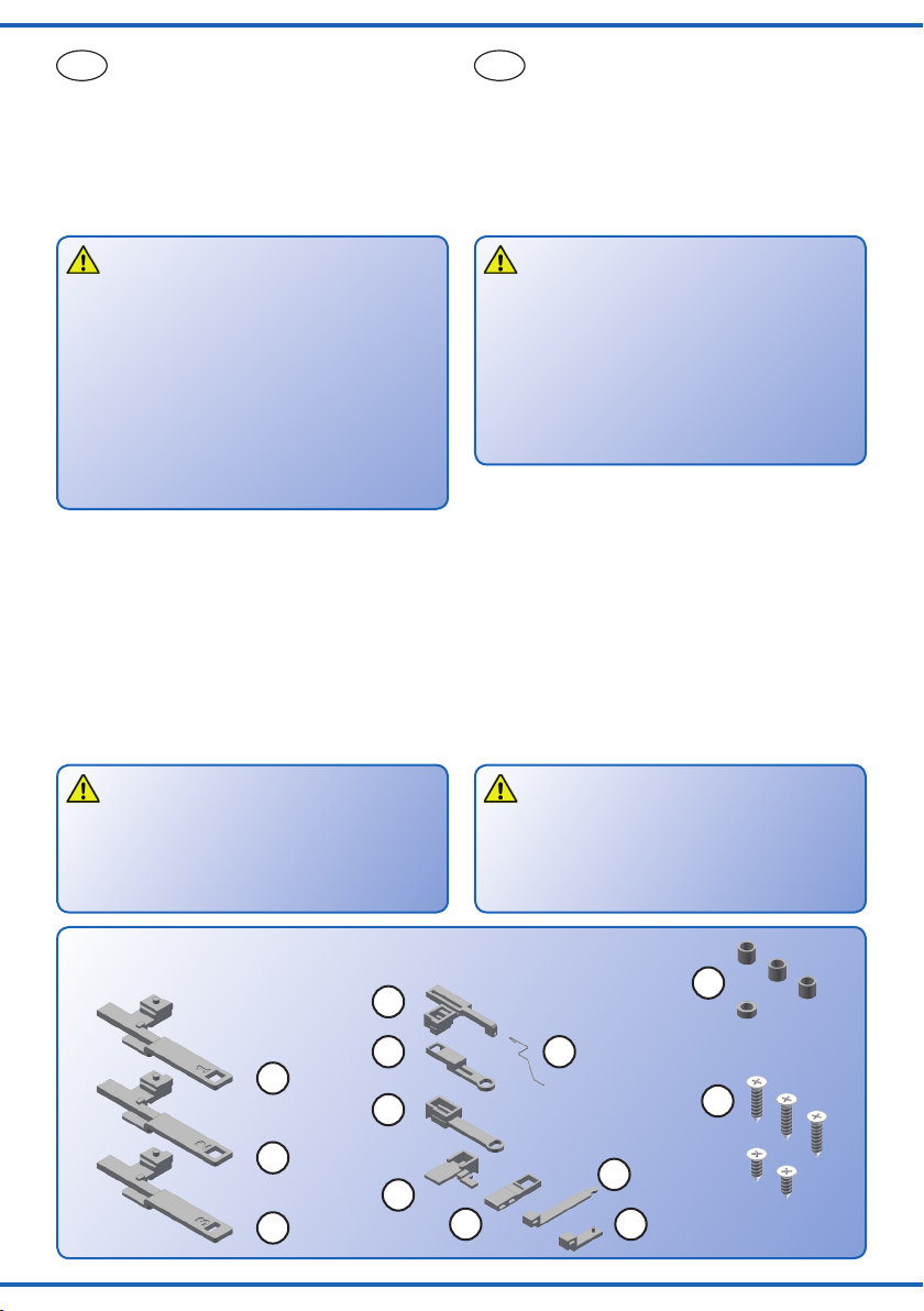
- Beutel mit Zubehörteilen zum Anbau des Antriebs an
verschiedene Weichentypen (Inhalt s. Abb. 1):
1) Märklin C-Gleis (DKW),
2) Märklin C-Gleis (Dreiwegweiche),
3) Märklin C-Gleis (einfache Weiche),
4) Roco geoLINE,
5) Roco geoLINE (Stelldraht),
6) Roco LINE mit Bettung,
7) Fleischmann Progleis,
8) Adapter für 90°-Abtriebe,
9) Roco LINE ohne Bettung, Piko A, Peco Streamline,
10) Märklin K-Gleis,
11) Tillig H0 Elite,
12) Distanzhülsen (4 Stück),
13) Befestigungsschrauben (5 Stück),
- diese Anleitung.
2. Einleitung
Funktionsumfang
Der Viessmann Weichenantrieb ist ein kraftvoller Univer-
salantrieb mit integriertem Digitaldecoder zum Einbau in
H0-Bettungsweichen sowie als unauffälliger Oberuran-
trieb für Weichen verschiedener Hersteller und Baugrößen.
Der Viessmann Weichenantrieb zeichnet sich durch vor-
bildgerecht langsame Bewegung der Weichenzungen
aus. Geschwindigkeit und Bewegungsablauf sind elektro-
nisch gesteuert und gewährleisten einen feinfühligen An-
trieb. Der Motor fährt nach Erreichen der jeweiligen End-
lage immer in eine Mittelposition ohne den Stellschieber
mitzunehmen. Auf diese Weise ist auch Handbetätigung
der Weiche möglich, ohne den Antrieb zu beschädigen.
Wenn aufgrund der Eigenschaften Ihrer Weiche die Be-
wegungsrichtung nicht mit der Schaltrichtung auf Ihrem
Eingabegerät übereinstimmt, können Sie im Digitalbetrieb
die Stellrichtung des Antriebs invertieren (s. Abb. 14).
Der integrierte Decoder versteht die Formate Märklin-Mo-
torola und DCC und kann die angeforderte Sollstellung
per RailCom an geeignete Digitalzentralen zurückmel-
den. Zusätzliche Kontakte für analoge Stellungsrückmel-
dung vervollständigen den Funktionsumfang.
Geeignete Gleissysteme
Für die unten aufgeführten Gleissysteme benden sich
im Lieferumfang geeignete Hebel zur direkten Montage.
Weitere Gleissysteme und Weichentypen auch ande-
rer Baugrößen sind prinzipiell ebenfalls verwendbar. Zur
Montage ist dann jedoch etwas Geschick erforderlich. Die
beigefügten Hebel lassen sich je nach Weichentyp auch
für andere Weichen verwenden.
- Märklin C- und K-Gleis
- Roco LINE mit und ohne Bettung
- Roco geoLINE (nicht Nr. 61160 / 61164)
- Fleischmann H0 Modellgleis
Checking the package contents
Check the contents of the package for completeness
after unpacking:
- turnout drive unit with cables,
- bag with different adapters and levers to mount the
drivetodifferentturnouttypes(contentseeg.1):
1) Märklin C-track (double slip switch),
2) Märklin C-track (three way turnout),
3) Märklin C-track (single turnout),
4) Roco geoLINE,
5) Roco geoLINE,
6) Roco LINE with ballast,
7) Fleischmannprotrack,
8) Adapter for 90° drive,
9) Roco LINE without ballast, Piko A, Peco Streamline,
10) MärklinK-track,
11) Tillig H0 Elite,
12) distance rolls (4 pieces),
13) screws (5 pieces),
- this manual.
2. Introduction
Functions
The Viessmann switch motor is a powerful universal drive
unit with integrated digital decoder. It can be mounted in
H0-turnoutswithbedofballastoroveroor.Theswitch
motor is compatible with turnouts of different manufac-
turers.
The Viessmann switch motor has an extraordinary and
thus very realistic slow movement of the point rails.
Speed and motion are controlled by the built-in electronic
which ensures a very sensitive adjustment. The motor
takes up a middle position after reaching the end posi-
tion, without taking the lever with it. This allows, to switch
the turnouts by hand.
If – due to the characteristics of your turnout – the direc-
tionsoftheturnoutdoesnottwiththeswitchingdirec-
tion of the digital command station, it is possible to set
the drive motor to reverse mode.
The integrated decoder is suitable for DC / AC, MM and
DCC and is able to send the requested position by Rail-
Com to corresponding digital command stations. Addi-
tional contacts for a conventional feedback complete the
functions of the switch motor.
Compatible track systems
The list below shows the track systems of different manu-
facturers, for which levers are included in the package.
Further track systems – and other gauges – can also be
used,buttherearenospecicleversetc.available,so
you need to handicraft a little bit. The enclosed levers can
be used for other track systems, too.
- MärklinC-andK-track
- Roco LINE with and without ballast
- Roco geoLINE (not No. 61160 / 61164)
- Fleischmann H0 model track

4
- Fleischmann H0 Progleis
- Piko A-Gleis
- Tillig H0 Elite
- Peco Streamline (Code 75)
Ansteuerung im Digitalbetrieb
Der Weichenantrieb 4554 enthält einen Multiprotokoll-
Decoder, der entweder Signale im DCC-Format oder im
Motorola-Format auswertet. Welches Datenformat der
Decoder auswertet, legt man bei der Einstellung der Digi-
taladresse fest.
Der Adressumfang ist von dem Format abhängig, mit
dem der Decoder angesteuert wird.
Motorola-Format: 255 Adressen
DCC- Format: 2048 Adressen
Ansteuerung im Analogbetrieb
Den Viessmann Weichenantrieb können Sie auch in ana-
log gesteuerten Modellbahnanlagen einsetzen. Sie kön-
nen ihn sowohl mit Wechselstrom- als auch mit Gleich-
strom betreiben.
Sobald Sie den Antrieb an Betriebsspannung anschlie-
ßen, erkennt der integrierte Decoder automatisch, ob er
analog oder digital angesteuert wird und stellt den ent-
sprechenden Betriebsmodus ein.
Verhalten bei Überlastung
Bei Kurzschlüssen oder anderer Überlastung schaltet der
Weichenantrieb nach einer Zeit von ca. 2 Sekunden ab
und fährt in die Mittelstellung zurück.
Rückmeldung mit RailCom
RailCom ist ein Zusatzprotokoll zur bidirektionalen Kom-
munikation in digitalen Modellbahnanlagen, die im DCC-
Format gesteuert werden. Es ermöglicht z. B. die Stel-
lungsrückmeldung der Weiche zur Digitalzentrale.
Das Versenden von RailCom-Messages ist nur in Anla-
gen möglich, in denen ein DCC-Signal an den Schienen
anliegt und seitens der Zentrale sowie der Booster eine
entsprechende Austastlücke im Datenstrom erzeugt wird.
Daher ist die Nutzung der RailCom-Funktion in einer rei-
nen Motorola-Umgebung nicht möglich.
Sofern der Decoder im Weichenantrieb die Austastlücke
registriert, sendet er nach einem erhaltenen Schaltbefehl
als Quittung die Sollstellung der Weiche zurück.
3. Einbau / Montage
Hinweis:
Sowohl mechanische als auch elektronische Bauteile
im Inneren des Weichenantriebs sind sehr empndlich.
Arbeiten Sie also sehr vorsichtig!
Alle Anschluss- und Montagearbeiten dürfen nur bei
abgeschalteter Betriebsspannung durchgeführt wer-
den.
Allgemeine Hinweise
Der Viessmann Weichenantrieb ist als Universalantrieb
für unterschiedliche Weichentypen konzipiert. Im Gehäu-
se ist die elektronische Steuerung inklusive Digitaldeco-
- FleischmannH0protrack
- Piko A-track
- Tillig H0 Elite
- Peco Streamline (Code 75)
Operation in digital mode
The switch motor contains a multiple protocol decoder,
that can operate with and automatically recognizes both
DCC or Motorola formats.
The number of addresses depends on the format being
used.
Motorola-format: 255 addresses
DCC-format: 2048 addresses
Operation in analogue mode
The Viessmann switch motor can be used in conventional
model railroad layouts. You may use AC or DC power
supply for operation.
The integrated controller and decoder recognizes auto-
matically if there is AC or DC power supply or a digital
signal and adjusts itself to the correct mode of operation.
Overload protection
If the switch motor recognizes a short circuit or an over-
load, it switches off to protect itself against destruction. At
rst,themotorbringsthedrivetothemid-position.The
whole process of switching off may last up to 2 seconds.
Feedback with RailCom
RailCom is a log for bi-directional communication in
digital model railway layouts controlled in DCC-format. It
allows e. g. the feedback of the address or the requested
position from the switch motor to the digital control unit.
Sending RailCom messages is only possible in layouts
with a DCC signal on the rails and if the command station
and / or the booster(s) generate a cut-out in the digital
signal. That’s why it is not possible to use RailCom in a
Motorola-system without DCC.
Whether the decoder of the switch motor registers the
RailCom cut-out, it sends back after an order it’s own
address and the requested position of the turnout to ac-
knowledge that it has received the order (so-called Rail-
Com broadcast datagramm).
3. Mounting and connection
Notice:
Be careful with the switch motor. Mechanical as well
as electronical components in the switch motor are
very sensitive.
Make sure that the power supply is switched off when
you mount the device and connect the wires!
General notice
The Viessmann switch motor is an universal drive for dif-
ferent types of turnouts. The case contains the electronic
control unit including the digital decoder and the drive unit
(motor, gear unit, thread and lever).

5
Fig. 2
Abb. 2
der sowie der Antriebsmotor inklusive mechanischem Teil
untergebracht (Gewindespindel, Abtriebshebel, Getriebe).
Der Weichenantrieb kann in jeder Lage montiert werden,
abhängig vom Weichentyp und Gleissystem.
Das Gehäuse ist systembedingt nicht hermetisch versie-
gelt. Durch die Öffnungen im Gehäuse können Kleinteile
wie Streumaterial etc. ins Innere gelangen und den An-
trieb zerstören.
Beachten Sie daher unbedingt die folgenden Hinweise:
Hinweis:
Achten Sie bei der Montage auf der Grundplatte da-
rauf, dass die Oberäche eben und sauber ist.
Unter dem Weichenantrieb darf kein Streumaterial
(Steine, Schotter etc.) verwendet werden. Ansonsten
können Getriebegehäuse und Mechanik verformt und
zerstört werden.
Achten Sie unbedingt darauf, dass kein Streumaterial
durch die Öffnungen des Gehäuses ins Innere gelan-
gen kann.
Weichenantrieb vorbereiten
Um den Weichenantrieb ordnungsgemäß an einer Wei-
che zu montieren, sind einige vorbereitende Arbeiten er-
forderlich. Sorgen Sie bitte als erstes für eine aufgeräum-
te und saubere Arbeitsäche. Legen Sie sich außerdem
folgendes Werkzeug bereit: eine feine Pinzette (möglichst
aus Kunststoff) sowie einen kleinen Schraubendreher
(Schlitz) zum vorsichtigen Abhebeln des Deckels.
1. Legen Sie den für Ihre Weiche passenden Hebel
bereit (aus dem Zubehörbeutel, s. Abb. 1).
2. Öffnen Sie vorsichtig den vorderen Deckel des
Weichenantriebs (Abb. 2) und legen Sie ihn beiseite.
Damit sind die Vorbereitungen abgeschlossen. Folgen
Sie nun den speziellen Hinweisen zu Ihrem Weichentyp
weiter unten.
The switch motor may be mounted in every position. The
used mounting place and position of the switch motor de-
pends on the used track system and turnout type.
The case is not hermetically sealed due to it’s concept.
Small parts like ballast etc. may get into the casing
through the openings and destroy the switch motor!
Therefore pay attention to the following notices:
Notice:
When mounting the switch motor, the ground plate has
to be even and clean.
Below the switch motor there must not be any mate-
rial like ballast etc. Otherwise the casing could be de-
formed and the mechanical parts could be destroyed.
Prevent small materials like e.g. ballast from getting
into the casing.
Preparing the switch motor
To mount the switch motor at a turnout, some prepara-
tionsarenecessary.Atrstyouneedacleanworkplace.
For the following work you need these tools: A small
tweezer (if possible, use some made of plastic) and a
small screwdriver to open the casing.
1. Choosethelever,whichtsforyourturnout/track
system(seeg.1).
2. Carefully open the front cover of the casing of the
switch(seeg.2)
Follownowthespecicinstructionsforyourturnout/
tracksystem.You’llndtheseinstructionsbelow.
1. Halterungen abspreizen
2. Deckel abheben
3. gewünschten Hebel einsetzen
4. Deckel wieder aufsetzen und einrasten
1. Spreadoffxtures
2. Take off front cover carefully
3. Put in the corresponding lever
4. Put the cover back on casing
Märklin C-Gleis (einfache Weiche)
Hebel: 3
Montage: in Bettung
1. Montieren Sie Hebel 3 gemäß Abb. 3.1 im Weichen-
antrieb und verschließen Sie anschließend das Ge-
häuse wieder mit dem Deckel.
2. Bringen Sie die Weiche in die zum Antrieb passende
Stellung (Der Hebel des Weichenantriebs muss in den
Hebel der Weiche greifen).
3. Legen Sie den Weichenantrieb gemäß Abb. 3.2 in die
Bettung der Weiche und xieren Sie ihn mit den pas-
senden Schrauben 2 x Nr. 13.
Märklin C-track (single turnout)
Lever: 3
Mounting: Into bed of ballast
1. Mountlever3asshowning.3.1intotheswitchmo-
tor. After mounting the lever, close the casing with the
cover.
2. Bring the turnout into the corresponding position of the
switch motor (the lever of the switch motor has to get
connected with the lever of the turnout).
3. Put the switch motor into the intended empty space of
theturnoutasshowning.3.2.
Fix the switch motor with the screws 2 x No. 13.

6
Fig. 4
Abb. 4
4.1 4.2
Abb. 3
3.1 3.2 3.3
2,2 x 6 mm
2,2 x 6 mm
Fig. 3
Märklin C-Gleis (Dreiwegweiche)
Hebel: 2 und 3
Montage: in Bettung
Zum Antrieb der Dreiwegweiche benötigen Sie zwei
Viessmann Weichenantriebe.
1. Montieren Sie die beiden Hebel gemäß Abb. 3.1
(oben) in den Weichenantrieben und verschließen Sie
anschließend die Gehäuse wieder.
2. Bringen Sie die Weiche in die zu den Antrieben pas-
sende Stellung (Die Hebel der Weichenantriebe müs-
sen in die Hebel der Weiche greifen).
3. Legen Sie die Weichenantriebe gemäß Abb. 4.1 in die
Bettung der Weiche und xieren Sie sie mit den pas-
senden Schrauben 4 x Nr. 13 (Abb. 4.2).
Märklin C-track (three way turnout)
Lever: 2 and 3
Mounting: Into bed of ballast
To drive this turnout, you need two Viessmann switch mo-
tors (one for each turning).
1. Mountthetwoleversasshowning.3.1intothe
switch motor. After mounting the lever, close the cas-
ing with the cover.
2. Bring the turnout into the corresponding positions of
the switch motors (the levers of the switch motors
have to get connected with the levers of the turnout).
3. Put the switch motors into the intended empty space
oftheturnoutasshowning.4.1.
Fix the switch motors with the screws 4 x No. 13.
Märklin C-Gleis (DKW)
Hebel: 1
Montage: in Bettung
1. Montieren Sie den Hebel gemäß Abb. 3.1 (links) im
Weichenantrieb und verschließen Sie anschließend
das Gehäuse wieder.
2. Bringen Sie die Doppelkreuzungsweiche in die zum
Antrieb passende Stellung (Der Hebel des Weichen-
antriebs muss in den Hebel der DKW greifen).
3. Legen Sie den Weichenantrieb gemäß Abb. 5 in die
Bettung der Weiche und xieren Sie ihn mit den pas-
senden Schrauben 2 x Nr. 13.
Märklin C-track (double slip switch)
Lever: 1
Mounting: Into bed of ballast
1. Mountlever1asshowning.3.1intotheswitchmo-
tor. After mounting the lever, close the casing with the
cover.
2. Bring the switch into the corresponding position of the
switch motor (the lever of the switch motor has to get
connected with the lever of the switch).
3. Put the switch motor into the intended empty space of
theturnoutasshowning.5.
Fix the switch motor with the screws 2 x No. 13.

7
Fig. 5
Abb. 5
5.1 5.2
2,2 x 6 mm
Fig. 6
Abb. 6
6.1 6.2 6.3
Roco LINE (ohne Bettung)
Hebel: 8 und 9
Montage: oberur, neben Gleis
1. Montieren Sie die Hebel gemäß Abb. 6.1 im Weichen-
antrieb und verschließen Sie anschließend das Ge-
häuse wieder.
2. Entfernen Sie den markierten Befestigungsring an der
Einkerbung mit einem scharfen Messer.
3. Bringen Sie die Weiche in die zum Antrieb passende
Stellung (Der Hebel des Weichenantriebs muss in den
Hebel der Weiche greifen).
4. Montieren Sie den Antrieb neben der Weiche (Abb.
6.2) und xieren Sie ihn mit den passenden
Distanzhülsen und Schrauben 2 x Nr. 13.
Bei Verwendung der EKW und der DKW entfernen Sie
bitte den Steg im Hebel 9 (Abb. 9.1) und montieren Sie
den Antrieb mit dem Deckel nach unten.
Roco LINE (without ballast)
Lever: 8 and 9
Mounting: Overground, beside the track
1. Mountlever1asshowning.6.1intotheswitchmo-
tor. After mounting the lever, close the casing with the
cover.
2. Cut off the fastening ring at the notch with a sharp
knifeasshowning.6.1.
3. Bring the turnout into the corresponding position of the
switch motor (the lever of the switch motor has to get
connected with the lever of the turnout).
4. Mount the switch motor beside the turnout as shown
ing.6.2.Fixtheswitchmotorwiththescrews2xNo.
13. Use the distance rolls!
When using a slip switch, cut off the bridge in lever 9 (see
g.9.1)andmounttheswitchmotorwiththecovertothe
ground.
Roco LINE (mit Bettung)
Hebel: 6
Montage: in Bettung
1. Montieren Sie den Hebel gemäß Abb. 7.1 im Wei-
chenantrieb und verschließen Sie anschließend das
Gehäuse wieder.
2. Entfernen Sie die markierten Befestigungsringe an
den Einkerbungen mit einem scharfen Messer.
3. Bringen Sie die Weiche in die zum Antrieb passende
Stellung (Der Hebel des Weichenantriebs muss in den
Hebel der Weiche greifen).
4. Montieren Sie den Antrieb mit dem Deckel nach unten
in der Weiche (Abb. 7.2).
Roco LINE (with bed of ballast)
Lever: 6
Mounting: Into bed of ballast
1. Mountlever6asshowning.7.1intotheswitchmo-
tor. After mounting the lever, close the casing with the
cover.
2. Cut off the fastening rings at the notch with a sharp
knifeasshowning.7.1.
3. Bring the turnout into the corresponding position of the
switch motor (the lever of the switch motor has to get
connected with the lever of the turnout).
4. Mount the switch motor into the intended empty space
oftheturnoutasshowning.7.2.

8
Fig. 7
Abb. 7
7.1 7.2 7.3
Fig. 8
Abb. 8
8.1 8.2 8.3
Fleischmann H0 Progleis
Hebel: 7
Montage: oberur, neben Gleis
1. Montieren Sie den Hebel gemäß Abb. 8.1 im Wei-
chenantrieb und verschließen Sie anschließend das
Gehäuse wieder.
2. Entfernen Sie den markierten Befestigungsring an der
Einkerbung mit einem scharfen Messer.
3. Bringen Sie die Weiche in die zum Antrieb passende
Stellung (Der Hebel des Weichenantriebs muss in den
Hebel der Weiche greifen).
4. Montieren Sie den Antrieb mit dem Deckel nach unten
neben der Weiche (Abb. 8.2) und xieren Sie ihn mit
den passenden Schrauben 2 x Nr. 13.
Fleischmann H0 pro track
Lever: 7
Mounting: Overground, beside the track
1. Mountlever7asshowning.8.1intotheswitchmo-
tor. After mounting the lever, close the casing with the
cover.
2. Cut off the fastening ring at the notch with a sharp
knifeasshowning.8.1.
3. Bring the turnout into the corresponding position of the
switch motor (the lever of the switch motor has to get
connected with the lever of the turnout).
4. Mount the switch motor with the cover to the ground
besidetheturnoutasshowning.8.2.Fixtheswitch
motor with the screws 2 x No. 13.
Piko A-Gleis und
Peco Streamline (Code 75)
Hebel: 8 und 9
Montage: oberur, neben Gleis
1. Montieren Sie die Hebel gemäß Abb. 9.1 im Weichen-
antrieb und verschließen Sie anschließend das Ge-
häuse wieder.
2. Entfernen Sie den markierten Befestigungsring an der
Einkerbung mit einem scharfen Messer.
3. Bringen Sie die Weiche in die zum Antrieb passende
Stellung (Der Hebel des Weichenantriebs muss in den
Hebel der Weiche greifen).
4. Montieren Sie den Antrieb neben der Weiche (Abb.
9.2 und 9.3) und xieren Sie ihn mit den passenden
Distanzhülsen und Schrauben 2 x Nr. 13.
Piko A-track and
Peco Streamline (Code 75)
Lever: 8 and 9
Mounting: Overground, beside the track
1. Mountthelevers8and9asshowning.9.1intothe
switch motor. After mounting the levers, close the cas-
ing with the cover.
2. Cut off the fastening ring at the notch with a sharp
knifeasshowning.9.1.
3. Bring the turnout into the corresponding position of the
switch motor (the lever of the switch motor has to get
connected with the lever of the turnout).
4. Mount the switch motor beside the turnout as shown
ing.9.2and9.3.Fixtheswitchmotorwiththe
screws 2 x No. 13. Use the distance rolls!

9
Fig. 9
Abb. 9
9.1
9.2 Piko
9.3 Peco
Tillig H0 Elite
Hebel: 8 und 11
Montage: oberur, neben Gleis
1. Montieren Sie die Hebel gemäß Abb. 10.1 im Wei-
chenantrieb und verschließen Sie anschließend das
Gehäuse wieder.
2. Entfernen Sie den markierten Befestigungsring an der
Einkerbung mit einem scharfen Messer.
3. Bringen Sie die Weiche in die zum Antrieb passende
Stellung (Der Hebel des Weichenantriebs muss in den
Hebel der Weiche greifen).
4. Montieren Sie den Antrieb neben der Weiche (Abb.
10.2) und xieren Sie ihn mit den passenden Di-
stanzhülsen und Schrauben 2 x Nr. 13.
Tillig H0 Elite
Lever: 8 and 11
Mounting: Overground, beside the track
1. Mountlevers8and11asshowning.10.1intothe
switch motor. After mounting the lever, close the cas-
ing with the cover.
2. Cut off the fastening ring at the notch with a sharp
knifeasshowning.10.1.
3. Bring the turnout into the corresponding position of the
switch motor (the lever of the switch motor has to get
connected with the lever of the turnout).
4. Mount the switch motor beside the turnout as shown
ing.10.2.Fixtheswitchmotorwiththescrews2x
No. 13. Use the distance rolls!
Steg mit Cutter entfernen.
Cut off bridge with cutter.

10
Fig. 10
Abb. 10
10.1 10.2 10.3
Fig. 11
Abb. 11
11.1 11.2 11.3
Märklin K-Gleis
Hebel: 8 und 10
Montage: oberur, neben Gleis
1. Montieren Sie die Hebel gemäß Abb. 11.1 im Wei-
chenantrieb und verschließen Sie anschließend das
Gehäuse wieder.
2. Entfernen Sie den markierten Befestigungsring an der
Einkerbung mit einem scharfen Messer.
3. Bringen Sie die Weiche in die zum Antrieb passende
Stellung (Der Hebel des Weichenantriebs muss in den
Hebel der Weiche greifen).
4. Montieren Sie den Antrieb neben der Weiche (Abb.
11.2) und xieren Sie ihn mit den passenden Di-
stanzhülsen und Schrauben 2 x Nr. 13.
Märklin K-track
Lever: 8 and 10
Mounting: Overground, beside the track
1. Mountthelevers8and10asshowning.11.1into
the switch motor. After mounting the lever, close the
casing with the cover.
2. Cut off the fastening ring at the notch with a sharp
knifeasshowning.11.1.
3. Bring the turnout into the corresponding position of the
switch motor (the lever of the switch motor has to get
connected with the lever of the turnout).
4. Mount the switch motor beside the turnout as shown
ing.11.2.Fixtheswitchmotorwiththescrews2x
No. 13. Use the distance rolls!
Roco geoLINE
Hebel: 4 und 5
Montage: in Bettung
1. Stecken Sie den Draht gemäß Abb. in den Hebel.
Achten Sie auf Links- bzw. Rechtsweiche.
2. Montieren Sie den Hebel gemäß Abb. 12.1 im Wei-
chenantrieb und verschließen Sie anschließend das
Gehäuse wieder.
3. Entfernen Sie den Befestigungsring und die Träger-
platte (Abb. 12.1) mit einem scharfen Messer.
4. Bringen Sie die Weiche in die zum Antrieb passende
Stellung (Der Hebel des Weichenantriebs muss in den
Hebel der Weiche greifen).
5. Montieren Sie den Antrieb neben der Weiche (Abb.
12.2 und 12.3) und xieren Sie ihn mit einer pas-
senden Distanzhülse und Schraube 13.
Roco geoLINE
Lever: 4 and 5
Mounting: Into bed of ballast
1. Putthestealwire(5)intothelever(seeg.12.1).
Observe if it is a left or right turnout.
2. Mountlever4asshowning.12.1intotheswitchmo-
tor. After mounting the lever, close the casing with the
cover.
3. Cut off the plate and fastening ring beside the cable
outputwithasharpknifeasshowning.12.1.
4. Bring the turnout into the corresponding position of the
switch motor (the lever of the switch motor has to get
connected with the lever of the turnout).
5. Mount the switch motor beside the turnout as shown
ing.12.2and12.3.Fixtheswitchmotorwithascrew
No. 13. Use the distance roll!

11
Fig. 12
Abb. 12
12.1
12.2 rechts / right 12.3 links / left
2,2 x 6 mm
4. Anschluss und Einrichtung
Vorsicht:
Alle Anschluss- und Montagearbeiten nur bei abge-
schalteter Betriebsspannung durchführen!
Ausschließlich nach VDE / EN-gefertigte
Modellbahntransformatoren verwenden!
Stromquellen unbedingt so absichern, dass es bei
einem Kurzschluss nicht zum Kabelbrand kommen
kann.
Widerstand und Diode an den Enden der
Anschlussdrähte sind für die Funktion erforderlich.
Keinesfalls entfernen! Widerstände nicht mit Isolati-
onsmaterial umhüllen, da sonst keine ausreichende
Kühlung möglich ist!
4. Connection and conguration
Caution:
Make sure that the power supply is switched off when
you mount the device and connect the wires!
Only use VDE/EN tested special model train trans-
formers for the power supply!
The power sources must be protected to prevent the
risk of burning wires.
Resistor and diode at the cables are needed for prop-
er function of the lamp. Never cut them off! Never
cover resistor or diode with insulation material, be-
cause they have to be cooled by surrounding air!
Rechtsweiche
turnout right
Linksweiche
turnout left

12
Sekundär
0-10-16 V~
16 V
Primär
230 V~
Gefertigt nach
VDE 0570
EN 61558
Lichttransformator
5200
Nur für trockene Räume
Primär 230 V 50 - 60 Hz
Sekundär max. 3,25 A52 VA
ta 25°CIP 40
10 V
0 V
Universal Tasten - Stellpult
5547
Viessmann
grün
gelb
braun
rot
/ yellow
/ green
brown
/ red
4554
5547
5200
Fig. 13
Abb. 13
Werkseinstellungen
Ab Werk ist der Decoder auf die Digitaladresse 1
(Motorola-Protokoll) eingestellt.
Analoger Betrieb
Im analogen Betrieb schalten Sie den Weichenantrieb mit
geeigneten Tastenstellpulten (z. B. Art.-Nr. Tastenstell-
pult 5547).
Schließen Sie den Weichenantrieb und das Tastenstell-
pult wie in Abb. 13 gezeigt an. Verwenden Sie einen ge-
eigneten Transformator (z. B. Art.-Nr. 5200).
Default settings
The factory setting for the digital address is 1 (Motorola
format).
Analogue mode of operation
In case that you use the Viessmann switch motor on
analogue layouts, use a push button panel (e. g. item-No.
5547 Universal push button panel).
Connect the switch motor and the push button panel as
showning.13.Useasuitabletransformer(e.g.item-
No. 5200).
Digitalbetrieb
Im digitalen Betrieb schalten Sie den Weichenantrieb
über eine Digitalzentrale. Legen Sie als erstes eine Di-
gitaldresse fest. Lesen Sie dazu die beiden folgenden
Kapitel und beachten Sie Abb. 15.
Nach Festlegung der Digitaladresse schließen Sie den
Weichenantrieb an, wie in Abb. 14 gezeigt.
Wenn aufgrund der Eigenschaften Ihrer Weiche die Be-
wegungsrichtung nicht mit der Schaltrichtung auf Ihrem
Eingabegerät übereinstimmt, können Sie die Stellrich-
tung des Antriebs umkehren. Schließen Sie nach der
Programmierung beide blauen Drähte gemeinsam an (s.
Abb. 14.1): bei Märklin/Motorola beide Drähte an den Mit-
telleiter; bei DCC an eine beliebige der beiden Schienen.
Einrichtung mit DCC-Zentralen
Zur digitalen Steuerung des Weichenantriebs müssen Sie
diesem zunächst eine Digitaladresse zuweisen.
Zur Steuerung im DCC-System gehen Sie wie folgt vor:
1. Schalten Sie das Digitalsystem aus, z. B. Not-Aus.
Es darf keine Spannung mehr am Gleis anliegen.
2. Verbinden Sie nur die rot markierte Steuerleitung
und die Stromversorgungsleitungen des Weichenan-
triebs (braun und gelb, s. Abb. 15) mit dem Gleis.
3. Schalten Sie das Digitalsystem ein.
4. Verbinden Sie die zweite (grün markierte) Steuer-
leitung gleichfalls mit dem Gleis (s. Abb. 14).
5. Senden Sie mit der Digitalzentrale nun für die
gewünschte DCC-Adresse einen Schaltbefehl.
Der Weichenantrieb empfängt den Befehl, registriert
die Adresse und quittiert dies durch Umschalten.
Digital mode of operation
In the digital mode of operation, you use a digital com-
mand station to control the switch motor. Please read
the following two chapters to learn how to set a digital
address.
Connect the switch motor to your digital layout as shown
ing.14.
If the properties of your switch cause its motion to be the
oppositeoftheswitchingdirectionspeciedbyyourinput
device, you have the possibility to reverse its direction.
Afterprogramming,connectbothbluewirestogether(g.
14.1): in a Märklin/Motorola system, connect both wires
to the middle rail; for DCC, connect both wires to any of
the two rails.
Cong. with DCC central units
To use the switch motor in a digital environment, you
havetoassignadigitaladdressatrst.Tocontrolthe
switch motor with a DCC-system, observe the following
instructions:
1. Switch off the digital system (e. g. emergency off).
There must not be any power at the rails.
2. Connect only the blue wire with the red marker and
the power supply wires of the switch motor (brown
andyellow,seeg.15)totherails.
3. Switch on the digital system.
4. Connect the second blue wire (green marker) to the
tracksignal,too(seeg.14).
5. Use the digital command station to send a switch-
request for the desired DCC-address. The switch mo-
tor receives the request, registers the address as it’s
own and as a receipt, it switches the turnout.

13
Mot. / DCC
4554
gelb
braun
Digitalzentrale
braun
/ yellow
brown
Digital command station
brown
Fig. 14
Abb. 14
DCC
4554
rot
braun
Digital-
zentrale
braun
gelb
/ red
brown
Digital
command
station
brown
yellow
MM
4554
rot
braun
braun
gelb
Digital-
zentrale
/ red
brown
brown
yellow
Digital
command
station
Fig. 14.1
Abb. 14.1
Damit ist der Weichenantrieb unter der neuen Adres-
se betriebsbereit. Falls Sie die Adresse künftig ändern
möchten, wiederholen Sie die Prozedur einfach.
CV-Programmierung:
Sie können den Weichenantrieb in DCC auch direkt über
das Hauptgleis (POM = Programming on the main) kon-
gurieren, sofern Ihre Digitalzentrale diese Funktion unter-
stützt. Dazu sendet die Zentrale per POM an die bekann-
te Decoderadresse die neuen Daten für die CVs 1 und 9.
Beachten Sie die Anleitung zu Ihrer Zentrale.
Einrichtung mit Motorola-Zentralen
Damit Sie den Weichenantrieb digital ansteuern können,
müssen Sie diesem zunächst eine Digitaladresse zuwei-
sen. Zur Steuerung im Märklin-Motorola-System gehen
Sie wie folgt vor:
1. Schalten Sie das Digitalsystem aus, z. B. Not-Aus.
Es darf keine Spannung mehr am Gleis anliegen.
2. Verbinden Sie nur die grün markierte Steuerleitung
und die Stromversorgungsleitungen des Weichenan-
triebs (braun und gelb, s. Abb. 15) mit dem Gleis.
3. Schalten Sie das Digitalsystem ein.
The switch motor is now ready to be used with the new
digital address. Whether you want to change the address,
you just have to repeat the described procedure.
Programming via CV:
Itispossibletocong.theswitchmotorviathetrack
signal (POM = programming on the main), if your digital
command station supports this feature. Therefore the
command station sends the new data in CVs 1 and 9 to
the old address. Observe the information in the manual of
your digital command station.
Cong. with Motorola central units
To use the switch motor in a digital environment, you
havetoassignadigitaladdressatrst.Tocontrolthe
switch motor with a Motorola-system, observe the fol-
lowing instructions:
1. Switch off the digital system (e. g. emergency off).
There must not be any power at the rails.
2. Connect only the blue wire with the green marker and
the power supply wires of the switch motor (brown
andyellow,seeg.15)totherails.
3. Switch on the digital system.
Anschluss nach Adressprogrammierung für invertierte Stellrichtung!
Connection after programming the address - use for reverse switching direction!

14
Mot. / DCC
4554
Motorola
DCC
gelb Digitalzentrale
braun
Adresse einstellen
grünes Kabel verbinden
rotes Kabel verbinden
rot
grün
/ yellow
Digital command station
/ brown
/ Set address
/ connect green cable
/ connect red cable
green
red
Fig. 15
Abb. 15
4. Verbinden Sie die zweite (rot markierte) Steuerleitung
gleichfalls mit dem Gleis (s. Abb. 14).
5. Senden Sie mit der Digitalzentrale nun für die ge-
wünschte Motorola-Adresse einen Schaltbefehl.
Der Weichenantrieb empfängt den Befehl, registriert
die Adresse und quittiert dies durch Umschalten.
Damit ist der Weichenantrieb unter der neuen Adres-
se betriebsbereit. Falls Sie die Adresse künftig ändern
möchten, wiederholen Sie die Prozedur einfach.
Beachten Sie: Wenn Sie eine Zentrale einsetzen, die so-
wohl das DCC- als auch das Motorola-Format sendet, ist
die Programmierung des Weichenantriebs im DCC-For-
mat empfehlenswert.
4. Connect the second blue wire (red marker) to the
tracksignaltoo(seeg.14).
5. Use the digital command station to send a switch-
request for the desired Motorola-address. The switch
motor receives the request, registers the address as
it’s own and as a receipt, it switches the turnout.
The switch motor is now ready to be used with the new
digital address. If you want to change the address, you
just have to repeat the described procedure.
Notice: If you use a multiprotocol digital command sta-
tion, which is able to use the Motorola- as well as the
DCC-system simultaneuously, it is recommended to pro-
gram the switch motor on a DCC-address.
Stellungsrückmeldung per Relais
Der Weichenantrieb verfügt über einen Transistor-Schalt-
ausgang zur Rückmeldung der Weichenstellung. Damit
kann er beispielsweise bistabile Relais schalten. Der
Kontakt wird jeweils am Ende des Stellweges der Weiche
für ca. 250 ms eingeschaltet.
Sie können über diese, als Lötächen ausgeführten, Kon-
takte die Stellung der Weichenzunge an ein geeignetes
Steuerungssystem zurückmelden oder Schaltvorgänge
wie eine separate Herzstückpolarisierung auslösen.
Aufgrund der geringen Belastbarkeit und der kurzen
Schaltzeit nutzen Sie auf jeden Fall ein Relais wie z. B.
das Elektronische Relais von Viessmann (Art.-Nr. 5552).
Zum Anschluss siehe Abb. 16.
Stellungsrückmeldung per RailCom
Der Weichenantrieb sendet über RailCom folgende Infor-
mationen an die Digitalzentrale:
- Eigene Digitaladresse
- Befehlsqittung mit Angabe der Sollstellung
Feedback via relais
The switch motor is equipped with a transistor-driven out-
put, which is able to feedback the position of the turnout.
This output is used to operate bistable relais. The contact
is turned on for approx. 250 ms, when the turnout reach-
es it’s respective end position.
By these contacts (soldering pads on the back of the cas-
ing), you may feedback the position of the turnout to a
suitable control system. The second use is to switch the
polarisation of the core of a turnout.
Due to the low maximum load of the contacts and the
short pulse length, it is important to use a relais (e. g. the
Viessmann electronic relay item-No. 5552) as shown in
g.16.
Feedback via RailCom
The switch motor sends via the RailCom protocol the fol-
lowing information to the digital command station:
-It’s own digital address
-A receipt with the requested turnout position

15
Fig. 16
Abb. 16
Elektr. Relais 5552
Viessmann
4554
3 x blau
Schaltkontakte
(als Lötflächen ausgeführt)
Max. Strom: 50 mA
/ blue
Feedback outputs
(soldering pads)
Max. current: 50 mA
Fig. 17
Abb. 17
5. Betrieb
Weichen schalten
Drücken Sie die entsprechende Taste auf dem Tasten-
stellpult (analoger Betrieb) oder senden Sie einen ent-
sprechenden Befehl an die Adresse des Weichenan-
triebs (digitaler Betrieb). Der Weichenantrieb schaltet die
Weiche vorbildgerecht langsam um. Dies dauert etwa 2
Sekunden. Während der Stellzeit speichert der Antrieb
einen weiteren Befehl, der eine andere als die aktuelle
Stellung bedeutet und führt diesen nach einer kurzen
Kühlzeit (ca. 0,5 Sek.) aus.
6. Wartung
Vorsicht:
Öffnen Sie unter keinen Umständen das Gehäuse
(Ausnahme: vorderer Deckel). Zerlegen Sie niemals
den Weichenantrieb. Zerstörung des Antriebs oder
Verletzungen können die Folge sein.
Der Viessmann Weichenantrieb ist wartungsfrei.
Wir empfehlen jedoch, die Gewindestange des Antriebs
regelmäßig (ca. alle 50.000 Schaltvorgänge) mit einem
winzigen Tropfen sehr dünnüssigen
synthetischen Öl (z. B. Viessmann
Feinmechaniköl SYN, Art.-Nr. 6858)
gemäß Abb. 17 zu schmieren.
5. Operation
Operate turnouts
Press the appropriate button on the push-button-panel
(analogue use) or send an appropriate request / order to
the address of the switch motor (digital use).
The switch motor turns now the turnout with a realistic
speed. This operation lasts approx. 2 seconds. During
this operation, the switch motor saves another request /
order, if this means another position and executes it after
a short break of about 0.5 seconds.
6. Maintenance
Caution:
Never open the casing (exception: front cover). Never
dismantle the switch motor. Destruction of the switch
motor or injury could occur.
The Viessmann switch motor is maintenance-free.
We recommend to lubricate the mechanical parts of the
product (thread) regularly (approx. every 50000 switches)
with a little drop of synthetic oil (e. g. Viessmann preci-
sionmechanicsoilSYN,item-No.6858)asshowning.
17.

Modellbauartikel, kein Spielzeug! Nicht geeignet für Kinder
unter 14 Jahren! Anleitung aufbewahren!
Model building item, not a toy! Not suitable for children
under the age of 14 years! Keep these instructions!
Ce n’est pas un jouet. Ne convient pas aux enfants de
moins de 14 ans ! C’est un produit décor! Conservez cette
notice d’instructions!
Não é um brinquedo!Não aconselhável para menores de
14 anos. Conservar a embalagem.
Modelbouwartikel, geen speelgoed! Niet geschikt voor
kinderen onder 14 jaar! Gebruiksaanwijzing bewaren!
Articolo di modellismo, non è un giocattolo! Non adatto
a bambini al di sotto dei 14 anni! Conservare instruzioni
per l’uso!
Artículo para modelismo ¡No es un juguete! No
recomendado para menores de 14 años! Conserva las
instrucciones de servicio!
DE
EN
FR
NL
IT
ES
PT
16
7. Fehlersuche & Abhilfe
Jedes Viessmann-Produkt wird unter hohen Qualitäts-
standards gefertigt und vor seiner Auslieferung geprüft.
Sollte es dennoch zu einer Störung kommen, können Sie
anhand der folgenden Punkte eine erste Überprüfung
vornehmen.
Weichenantrieb schaltet hörbar, aber die Weiche schal-
tet nicht um.
- Prüfen Sie, ob der verwendete Hebel zum Weichentyp
passt und korrekt gemäß Anleitung eingebaut wurde.
- Mögliche Ursache: Es wurde ein falscher Hebel ver-
wendet und / oder der Hebel falsch eingebaut.
Antrieb wird sehr heiß und / oder beginnt zu qualmen.
- Trennen Sie sofort die Verbindung zur Versorgungs-
spannung!
- Prüfen Sie, ob der Weichenantrieb gemäß Anleitung
verkabelt wurde.
- Mögliche Ursache: Kurzschluss. Der Antrieb wurde
nicht ordnungsgemäß angeschlossen oder ein Metall-
teil ist ins Innere des Weichenantriebs geraten.
Wenn Sie die Fehlerursache nicht nden können, senden
Sie den Weichenantrieb bitte in der Originalverpackung
zur Reparatur ein. (Adresse s. u.)
7. Trouble-Shooting
Every Viessmann-product is manufactured under high
quality standards and is tested before delivery. If there is
afaultnevertheless,youcandoarstcheck.
Switch motor works audible, but the turnout does not
move.
- Checkiftheusedlevertstotheturnoutandifitis
correctly mounted as shown in this manual!
- Possible cause: An incompatible lever was installed
and / or the lever was built in false.
Switch motor is getting very hot and / or starts to smoke.
-Disconnect the system from the mains immediately!
-Check if the wiring was made correctly as shown in
this manual.
- Possible cause: Short circuit. The switch motor was
not connected correctly or a metal part had been
reaching into the casing.
If the product is damaged, send it in the original package
directly for repair to your local dealer or to the Viessmann
company (see below for address).
Modellspielwaren GmbH
8. Technical data
Operating voltage (analogue): 14-16 V ~
Operating voltage (digital): 12-20 V =/digital voltage
Current consumption (without load): approx. 30 mA
Current consumption (switch moment): < 100 mA
Data format: DCC and Motorola (MM)
Feedback log: RailCom
Max. total current (feedback outputs): 50 mA
Protected to: IP 00
Ambient temperature in use: +8 – +35 °C
Comparative humidity allowed: max. 85 %
Weight: 10.7 g (without lever)
Dimensions: 80.5 mm x 27 mm x 5.8 mm
8. Technische Daten
Betriebsspannung (analog): 14-16 V ~
Betriebsspannung (digital): 12-20 V =/Digitalspannung
Stromaufnahme (Ruhestrom): ca. 30 mA
Stromaufnahme (im Schaltmoment): < 100 mA
Datenformat: DCC und Märklin-Motorola
Rückmeldeprotokoll: RailCom
Kontaktbelastbarkeit (Rückmelderausgänge): 50 mA
Schutzart: IP 00
Umgebungstemperatur (Betrieb): +8 - +35 °C
Zulässige relative Luftfeuchtigkeit: max. 85 %
Gewicht: 10,7 g ohne Hebel
Abmessungen: 80,5 mm x 27 mm x 5,8 mm
RailCom ist ein eingetragenes Warenzeichen der / is a registered trademark of Lenz-Elektronik GmbH, Gießen.
Märklin ist ein eingetragenes Warenzeichen der / is a registered trademark of Gebr. Märklin & Cie GmbH, Göppingen.
Motorola ist ein eingetragenes Warenzeichen der / is a registered trademark of Motorola Inc., Tempe-Phoenix / Arizona (USA).
Weitere Produkt- oder Firmennamen können Marken oder Handelsnamen ihrer jeweiligen Inhaber sein.
92560
Stand 04/sw
03/2015
Ho/Me
Die aktuelle Version der Anleitung nden Sie auf der
Viessmann-Homepage unter der Artikelnummer.
The latest version of the manual can be looked up at the
Viessmann homepage using the item-No.
Table of contents
Other Viessmann Engine manuals
Popular Engine manuals by other brands

Lenze
Lenze m850 Mounting and switch-on instructions

Clarke
Clarke LC2A Operation and maintenance instruction manual

BRP
BRP ROTAX FR 125 MAX Repair manual

Assun
Assun AM-CL2847GAE Series product manual

ePropulsion
ePropulsion VAQUITA owner's manual

GOSS Power Products
GOSS Power Products AP156F operating instructions