Viessmann 4559 User manual

Bedienungsanleitung
Operation Manual
AC
~
DC
=
DCC MM
H0 Motorischer Weichenantrieb
für Roco geo-Line Weichen
H0 Point motor for
Roco geo-Line points
4559
1. Wichtige Hinweise ...................................... 2
2. Lieferumfang .............................................. 2
3. Einleitung .................................................... 3
4. Einbau / Montage ....................................... 4
5. Anschluss und Einrichtung ......................... 6
6. Betrieb ........................................................ 12
7 Wartung ...................................................... 13
8. Fehlersuche & Abhilfe ................................ 13
9. Technische Daten ...................................... 16
1. Important information ................................. 2
2. Content ....................................................... 2
3. Introduction ................................................ 3
4. Mounting and Connections.......................... 4
5. Connection and Conguration..................... 6
6. Operation ................................................... 12
7. Maintenance ............................................... 13
8. Troubleshooting .......................................... 13
9. Technical data ........................................... 16

2
DE EN
Fig. 1
Abb. 1
1. Wichtige Hinweise
Bitte lesen Sie vor der ersten Anwendung des Produk-
tes bzw. dessen Einbau diese Bedienungsanleitung
aufmerksam durch und bewahren Sie sie auf. Sie ist Teil
des Produktes.
Das Produkt richtig verwenden
Das Produkt darf ausschließlich dieser Anleitung ge-
mäß verwendet werden. Dieser Antrieb ist bestimmt
- zum Einbau an/in eine Modelleisenbahnweiche
- zum Betrieb mit einer konventionellen Modellbahn-
steuerung oder einer Digitalzentrale, welche die
Digitalsysteme Märklin-Motorola und/oder NMRA-
DCC verwendet
- zum Betrieb in trockenen Räumen.
Jeder darüber hinausgehende Gebrauch gilt als nicht
bestimmungsgemäß. Für daraus resultierende Schä-
den haftet der Hersteller nicht.
2. Lieferumfang
Vorsicht:
Der Antrieb besteht aus einer empndlichen
Elektronik- und Mechanikbaugruppe.
Öffnen Sie das weitere Gehäuse unter keinen
Umständen. Zerstörung des Antriebs oder Ver-
letzungen können die Folge sein.
Packungsinhalt überprüfen
Kontrollieren Sie nach dem Auspacken den Lieferumfang
auf Vollständigkeit:
- Weichenantrieb mit Anschlusskabel und im Kabel
bendlichem Decoder mit Vorwiderstand,
- 2 Schrauben,
- diese Anleitung.
1. Important information
Please read this manual completely and attentively befo-
re using the product for the rst time. Keep this manual. It
is part of the product.
Using the product for it’s correct
purpose
This product must only be used as required in this
manual. This point motor is intended
- for installation in turnouts of model railroad layouts,
- for connection to an authorized model railroad trans-
former or an electrical control system connected to
one or a digital command system (DCC or Mot.),
- for operation in a dry area.
Using the product for any other purpose is not ap-
proved and is considered incorrect. The manufacturer
cannot be held responsible for any damage resulting
from the improper use of this product.
2. Content
Caution:
The point motor contains very sensitive mechani-
cal and electronical components.
Never open the back cover of the point motor.
That may result in destruction of the motor or
injury.
Checking the package contents
Check the contents of the package for completeness
after unpacking:
- turnout drive unit with cable and in the cable located
decder including resistor,
- 2 screws,
- this manual.
Packungsinhalt
Package content

3
3. Einleitung
Funktionsumfang
Der Viessmann Weichenantrieb ist ein kraftvoller spezi-
eller Antrieb mit zugehörigem Digitaldecoder zum Einbau
in Roco geo-Line Weichen.
Der Viessmann Weichenantrieb zeichnet sich durch vor-
bildgerecht langsame Bewegung der Weichenzungen aus.
Geschwindigkeit und Bewegungsablauf sind elektronisch
gesteuert und gewährleisten einen feinfühligen Antrieb.
Hinweis:
Der Antrieb sollte nicht manuell verstellt werden,
um eventuelle Beschädigungen zu vermeiden.
Bitte das manuelle Schalten nicht erzwingen!
Wenn aufgrund der Eigenschaften Ihrer Weiche die Be-
wegungsrichtung nicht mit der Schaltrichtung auf Ihrem
Eingabegerät übereinstimmt, können Sie im Digitalbetrieb
die Stellrichtung des Antriebs invertieren (Abb. 4).
Der zugehörige Decoder versteht die Formate Märklin-
Motorola und DCC und kann die angeforderte Sollstel-
lung oder die Ist-Stellung per RailCom an geeignete Digi-
talzentralen (z. B. Viessmann Commander Art.-Nr. 5300)
zurückmelden. Zusätzliche Schaltausgänge für konventi-
onelle Stellungsrückmeldung vervollständigen den Funk-
tionsumfang. Deren Funktion ist kongurierbar.
Geeignete Gleissysteme
Dieser spezielle Viessmann Antrieb kann nur in Verbin-
dung mit Roco geo-Line Weichen benutzt werden.
Der Antrieb kann in folgende Roco geo-Line Weichen
eingebaut werden:
- 61140 Weiche 22,5° links
- 61141 Weiche 22,5° rechts
- 61154 Bogenweiche R3/4 links
- 61155 Bogenweiche R3/4 rechts
- 61160 Dreiwegweiche DWW 22,5° (2 Stück Antrieb)
- 61164 Doppelkreuzungsweiche DKW 22,5°
(2 Stück Antrieb)
Ansteuerung im Digitalbetrieb
Der Spezielle Roco geo-Line Weichenantrieb 4559 ent-
hält einen Multiprotokoll-Decoder, der entweder
Signale im DCC-Format oder im Motorola-Format
auswertet. Welches Datenformat der Decoder auswertet,
legt man bei der Einstellung der Digitaladresse fest.
Der Adressumfang ist von dem Format abhängig, mit
dem der Decoder angesteuert wird.
Motorola-Format: 320 (1020 bei entsprechender
Zentrale) Adressen.
DCC- Format: 2047 Adressen.
Ansteuerung im Analogbetrieb
Den Viessmann Weichenantrieb können Sie auch in kon-
ventionell gesteuerten Modellbahnanlagen einsetzen.
Sie können ihn sowohl mit Wechselstrom als auch mit
Gleichstrom betreiben.
3. Introduction
Functions
The Viessmann point motor is a powerful special drive
unit with associated digital decoder. It can be mounted in
Roco geo-Line turnouts.
The Viessmann point motor has an extraordinary and
thus very realistic slow movement of the point rails.
Speed and motion are controlled by the built-in electronic
which warrants a very sensitive adjustment.
Notice:
The drive should not be operated manually to
avoid any damage. Please do not force the
manual shifting!
If – due to the characteristics of your turnout – the direc-
tion of the turnout doesn’t t with the switching direction
of the digital command station, it is possible to set the
drive motor to reverse mode.
The associated decoder is suitable for DC / AC, MM and
DCC and is able to send the requested position or the
actual position by RailCom to corresponding digital com-
mand stations (e. g. Viessmann Commander item-No.
5300). Additional switching outputs for a conventional
feedback complete the functions of the point motor. Their
function is congurable.
Compatible Track Systems
This special Viessmann turnout drive is only suitable for
Roco geo-Line turnouts.
The drive can be installed in the following Roco geo-Line:
- 61140 turnout 22,5° left
- 61141 turnout 22,5° right
- 61154 curved tunout R3/4 left
- 61155 curved turnout R3/4 right
- 61160 three way turnout, DWW 22,5°
(2 pieces drives)
- 61164 double slip switches, DKW 22,5°
(2 pieces drives)
Operation in digital mode
The special Roco geo-Line point motor 4559 contains a
multiple protocol decoder, that can operate with and auto-
matically recognises both DCC or Motorola formats.
The number of addresses depends on the format being
used.
Motorola-Format: 320 (1020 with appropriate
command station) addresses.
DCC- Format: 2047 addresses.
Operation in analogue mode
The Viessmann point motor can be used in conventional
model railroad layouts. You may use AC or DC power
supply for operation.
The integrated controller and decoder recognizes auto-
matically if there is AC or DC power supply or a digital
signal and adjusts itself to the correct mode of operation.

4
Sobald Sie den Antrieb an Betriebsspannung anschlie-
ßen, erkennt der integrierte Decoder automatisch, ob er
analog oder digital angesteuert wird und stellt den
entsprechenden Betriebsmodus ein.
Verhalten bei Überlastung
Bei mechanischer Überlastung schaltet der Weichen-
antrieb nach einer kurzen Zeit ab.
Rückmeldung mit RailCom
RailCom ist ein Zusatzprotokoll zur bidirektionalen Kom-
munikation in digitalen Modellbahnanlagen, die im DCC-
Format gesteuert werden. Es ermöglicht z. B. die Stel-
lungsrückmeldung der Weiche zur Digitalzentrale.
Das Versenden von RailCom-Messages ist nur in Anla-
gen möglich, in denen ein DCC-Signal an den Schienen
anliegt und seitens der Zentrale bzw. der Booster eine
entsprechende Austastlücke im Datenstrom erzeugt wird.
Daher ist die Nutzung der RailCom-Funktion in einer rei-
nen Motorola-Umgebung nicht möglich.
Sofern der Decoder im Weichenantrieb die Austastlücke
registriert, sendet er nach einem erhaltenen Schaltbefehl
als Quittung die Sollstellung und Iststellung der Weiche
zurück. Bei drehendem Motor wird die geschätzte übrige
Zeit zurückgegeben, bis der Motor zum Stehen kommt.
4. Einbau / Montage
Hinweis:
Sowohl mechanische als auch elektronische Bau-
teile im Inneren des Weichenantriebs und des
Decoders sind sehr empndlich. Arbeiten Sie also
sehr vorsichtig!
Vorsicht:
Alle Anschluss- und Montagearbeiten dürfen nur
bei abgeschalteter Betriebsspannung durch-
geführt werden.
Allgemeine Hinweise
Das Gehäuse ist systembedingt nicht hermetisch versie-
gelt. Durch die Öffnungen im Gehäuse können Kleinteile
wie Streumaterial etc. ins Innere gelangen und den
Antrieb zerstören.
Beachten Sie daher unbedingt die folgenden Hinweise:
Hinweis:
Achten Sie bei der Montage auf der Grundplatte
darauf, dass die Oberäche eben und sauber ist.
Unter dem Weichenantrieb darf kein Streumaterial
(Steine, Schotter etc.) verwendet werden. Anson-
sten können Getriebegehäuse und Mechanik ver-
formt und zerstört werden.
Achten Sie unbedingt darauf, dass kein Streu-
material durch die Öffnungen des Gehäuses ins
Innere gelangen kann.
Overload protection
If the point motor recognizes a mechanical overload, it
switch off to protect itself against destruction. The whole
process of switching off may last up to a short time.
Feedback with RailCom
RailCom is a protocol for bi-directional communication in
digital model railway layouts controlled in DCC. It allows
e. g. the feedback of the address or the requested posi-
tion from the point motor to the digital command station.
Sending RailCom messages is only possible in layouts
with a DCC signal on the rails and if the command station
and / or the booster(s) generate a cut-out in the digital
signal. That’s why it is not possible to use RailCom in a
Motorola system without DCC.
Whenever the decoder registers the RailCom cut-out, it
answers the switching commands with the current state
of the turnout. In case of a moving motor, the estimated
remaining movement time is reported.
4. Mounting and Connections
Notice:
Be careful with the point motor. Mechanical as
well as electronical components in the point motor
and the decoder are very sensitive.
Caution:
Make sure that the power supply is switched
off when you mount the device and connect the
wires!
General notice
The case is not hermetically sealed due to its concept.
Small parts like ballast etc. may get into the casing
through the openings and destroy the point motor!
Therefore pay attention to the following notices:
Notice:
When mounting the point motor, the ground plate
has to be even and clean.
Below the point motor there must not be any ma-
terial like ballast etc. Otherwise the casing could
be deformed and the mechanical parts could be
destroyed.
Prevent small materials like e.g. ballast from get-
ting into the casing.

5
Fig. 2
Abb. 2
Fig. 3
Abb. 3
Weichenantrieb vorbereiten
Um den Weichenantrieb ordnungsgemäß an einer Wei-
che zu montieren, sind einige vorbereitende Arbeiten er-
forderlich. Sorgen Sie bitte als erstes für eine aufgeräum-
te und saubere Arbeitsäche. Legen Sie sich außerdem
folgendes Werkzeug bereit: eine feine Pinzette (möglichst
aus Kunststoff), einen kleinen Schraubendreher.
Legen Sie den Antrieb an die vorgesehene Position in der
Weiche und schrauben Sie ihn an den Anschraubdohmen
fest (Abb. 2 und 3).
Preparing the point motor
To mount the point motor at a turnout, some preparations
are necessary. At rst you need a clean workplace. For
the following work you need these tools: A small tweezer
(if possible, use one made of plastic), a small screwdriver
as well as a small hammer and a metal pin.
Insert the drive into the designated location in the turnout
and fasten it with the screws on the screw posts (g. 2
and 3).

6
5. Anschluss und Einrichtung
Vorsicht:
Alle Anschluss- und Montagearbeiten dürfen nur
bei abgeschalteter Betriebsspannung durchge-
führt werden!
Verwenden Sie nur nach VDE/EN-gefertigte
Modellbahntransformatoren!
Sichern Sie die Stromquellen unbedingt so ab,
dass es bei einem Kurzschluss nicht zum Kabel-
brand kommen kann!
Werkseinstellungen
Ab Werk ist der Decoder auf die Digitaladresse 1
(DCC-Protokoll) eingestellt. Weitere Kongurationsmög-
lichkeiten entnehmen Sie bitte der CV-Tabelle auf Seite
11.
Konventioneller (analoger) Betrieb
Im konventionellen (analogen) Betrieb schalten Sie den
Weichenantrieb mit geeigneten Tastenstellpulten (z. B.
Viessmann Tastenstellpult Art.-Nr. 5547).
Schließen Sie den Weichenantrieb und das Tastenstell-
pult wie in Abb. 4 gezeigt an. Verwenden Sie einen geeig-
neten Transformator (z. B. Viessmann Art.-Nr. 5200).
Digitalbetrieb
Dieser Decoder lässt sich als Schaltartikel ansteuern. Er
bietet aber auch den Komfort, auf einer Lokadresse an-
gesteuert werden zu können. Dies kommt den Modell-
bahnern entgegen, deren Zentrale keinen bequemen Zu-
griff auf Schaltartikel ermöglicht.
Im digitalen Betrieb schalten Sie den Weichenantrieb
über eine Digitalzentrale. Legen Sie als erstes eine Di-
gitaldresse fest. Lesen Sie dazu die beiden folgenden
Kapitel und beachten Sie Abb. 6.
Nach Festlegung der Digitaladresse schließen Sie den
Weichenantrieb an (Abb. 5).
Wenn aufgrund der Eigenschaften Ihrer Weiche die Be-
wegungsrichtung nicht mit der Schaltrichtung auf Ihrem
Eingabegerät übereinstimmt, können Sie die Stellrich-
tung des Antriebs umkehren. Schließen Sie nach der Pro-
grammierung beide blauen Drähte gemeinsam an (Abb.
5.1): bei Märklin/Motorola beide Drähte an den Mittel-
leiter; bei DCC an eine beliebige der beiden Schienen.
Alternativ können Sie die Schaltrichtung in der CV 36
ändern.
Einrichtung mit DCC-Zentralen
Zur digitalen Steuerung des Weichenantriebs müssen Sie
diesem zunächst eine Digitaladresse zuweisen.
Zur Steuerung im DCC-System gehen Sie wie folgt vor:
1. Schalten Sie das Digitalsystem aus, z. B. Not-Aus.
Es darf keine Spannung mehr am Gleis anliegen.
2. Verbinden Sie nur die rot markierte Steuerleitung
und die Stromversorgungsleitungen des Weichenan-
triebs (braun und gelb, Abb. 6) mit dem Gleis.
3. Schalten Sie das Digitalsystem ein.
4. Verbinden Sie nun die zweite (grün markierte) Steuer-
leitung gleichfalls mit dem Gleis (Abb. 5).
5. Connection and Conguration
Caution:
Make sure that the power supply is switched
off when you mount the device and connect the
wires!
Only use VDE/EN tested special model train
transformers for the power supply!
The power sources must be protected to prevent
the risk of burning wires.
Default settings
The factory setting for the digital address is 1 (DCC for-
mat). Please nd further conguration options in the CV
table on page 11.
Conventional mode of operation
(analogue)
In case that you use the Viessmann point motor on con-
ventional layouts, use a push button panel (e. g. Push
Button Panel item-No. 5547).
Connect the point motor and the push button panel as
shown in gure 4. Use a suitable transformer (e. g. item-
No. 5200).
Digital mode of operation
This decoder can be controlled as an accessory decoder.
However, it also offers the option to be controlled with a
locomotive address. This is particularly useful for model-
lers who do not have a command station with easy ac-
cess to accessories.
In the digital mode of operation, you use a digital com-
mand station to control the point motor. Please read the
following two chapters to learn how to set a digital ad-
dress.
Connect the point motor to your digital layout as shown
in g. 5.
If the properties of your turnout cause its motion to be the
opposite of the switching direction specied by your input
device, you have the possibility to reverse its direction.
After programming, connect both blue wires together (g.
5.1): in a Märklin/Motorola system, connect both wires to
the middle rail; for DCC, connect both wires to any of the
two rails.
Congure with DCC command stations
To use the point motor in a digital environment, at rst you
have to assign a digital address. To control the point motor
with a DCC-system, observe the following instructions:
1. Switch off the digital system (e. g. emergency off).
There must not be any power at the rails.
2. Connect only the blue wire with the red marker and
the power supply wires of the point motor (brown and
yellow, g. 6) to the rails.
3. Switch on the digital system.
4. Connect the second blue wire (green marker) to the
track signal too (g. 5).

7
5. Senden Sie mit der Digitalzentrale nun für die
gewünschte DCC-Adresse einen Schaltbefehl.
Der Weichenantrieb empfängt den Befehl, registriert
die Adresse und quittiert dies durch Umschalten.
Damit ist der Weichenantrieb unter der neuen Adres-
se betriebsbereit. Falls Sie die Adresse künftig ändern
möchten, wiederholen Sie die Prozedur einfach.
Programmieren am Programmiergleis
Die Konguration des Antriebs können Sie auch direkt
an dem Programmierausgang von Zentralen, die DCC-
kompatibel sind, vornehmen. Verbinden Sie dazu die An-
schlüsse des Weichenantriebs wie in Abb. 5 gezeigt mit
dem Programmierausgang Ihrer Zentrale.
Die Adresse des Antriebs wird in zwei CVs programmiert.
In CV 1 steht das untere Byte (LSB) der Adresse, in CV 9
das obere Byte (MSB).
Das Umrechnen der Adresse geschieht wie im folgenden
beschrieben. Wenn Sie eine Adresse zwischen 1 und 255
eingeben wollen, so schreiben Sie diesen Wert direkt in
CV 1. Den Wert in CV 9 setzen Sie auf Null. Höhere Wer-
te als 255 müssen aufgeteilt werden in das MSB und das
LSB. Teilen Sie die gewünschte Adresse durch 256 und
ermitteln Sie das ganzzahlige Ergebnis und den Rest.
Beispiele:
5. Use the digital command station to send a turnout-
request for the desired DCC-address. The point motor
receives the request, registers the address as its own
and as a receipt, it switches the turnout.
The point motor is now ready to be used with the new
digital address. Whenever you want to change the ad-
dress, you just have to repeat the described procedure.
Programming on the programming track
The conguration of the drive can also be accomplished
by connecting it directly to the programming output of the
command station. Simply connect the terminals of the
turnout drive to the programming output of the command
station as shown in g. 5.
The address of the drive is programmed in two CVs.
In CV 1 you set the lower Byte (LSB) of the address, in
CV 9 the upper Byte (MSB).
The address is established as described below. Write
the address value directly into CV 1 if you wish to assign
an address between1 and 255. Set CV 9 to 0. Higher
addresses than 255 must be split into the MSB and the
LSB: Divide the desired address by 256 and determine
the result without decimal points as well as the remain-
der.
Examples:
Adresse ganzzahliges
Ergebnis
Rest CV 9 = MSB CV 1 = LSB
256 1010
911 3 911-256x3=143 3 143
1025 4 1025-256x4=1 4 1
Die weiteren Einstellmöglichkeiten entnehmen Sie der
CV-Tabelle. In CV 40 können Sie auch das Protokoll fest-
legen, auf das der Weichenantrieb später „hört“.
Auf Befehle am Programmierausgang einer DCC-kompa-
tiblen Zentrale hört der Decoder immer unabhängig vom
eingestellten Protokoll.
Einrichtung mit Motorola-Zentralen
Damit Sie den Weichenantrieb digital ansteuern können,
müssen Sie diesem zunächst eine Digitaladresse zuwei-
sen. Zur Steuerung im Märklin-Motorola-System gehen
Sie wie folgt vor:
1. Schalten Sie das Digitalsystem aus, z. B. Not-Aus.
Es darf keine Spannung mehr am Gleis anliegen.
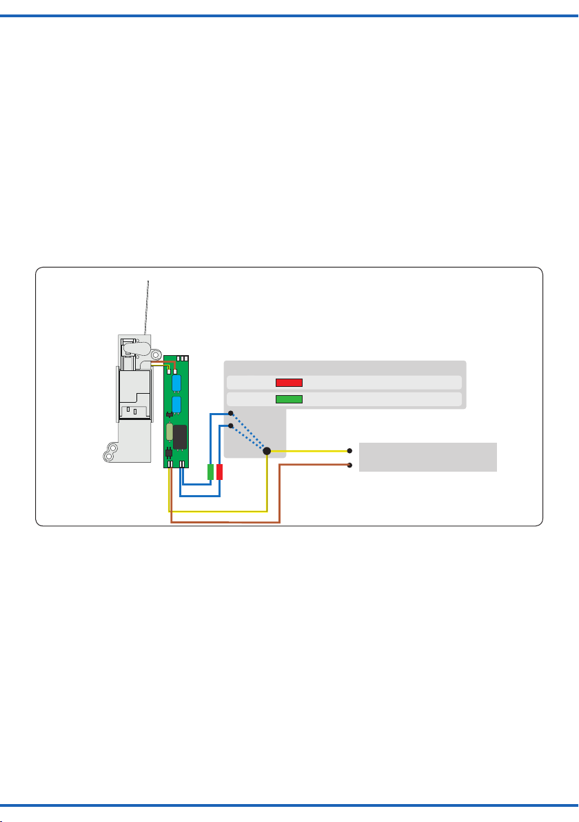
2. Verbinden Sie nur die grün markierte Steuerleitung
und die Stromversorgungsleitungen des Weichenan-
triebs (braun und gelb, Abb. 6) mit dem Gleis.
3. Schalten Sie das Digitalsystem ein.
4. Verbinden Sie die zweite (rot markierte) Steuerleitung
gleichfalls mit dem Gleis (Abb. 5).
5. Senden Sie mit der Digitalzentrale nun für die ge-
wünschte Motorola-Adresse einen Schaltbefehl.
Der Weichenantrieb empfängt den Befehl, registriert
die Adresse und quittiert dies durch Umschalten.
Damit ist der Weichenantrieb unter der neuen Adres-
se betriebsbereit. Falls Sie die Adresse künftig ändern
möchten, wiederholen Sie die Prozedur einfach.
Further programming options are listed in the CV table.
You may also set the desired digital protocol in CV 40.
The decoder will respond to commands of the program-
ming output of a DCC compatible command station
regardless of the set protocol.
Congure with Motorola central units
To use the point motor in a digital environment, you have
to assign a digital address at rst. To control the point
motor with a Motorola-system, observe the following
instructions:
1. Switch off the digital system (e. g. emergency off).
There must not be any power at the rails.
2. Connect only the blue wire with the green marker and
the power supply wires of the point motor (brown and
yellow, g. 6) to the rails.
3. Switch on the digital system.
4. Connect the second blue wire (red marker) to the
track signal too (g. 5).
5. Use the digital command station to send a turnout-
request for the desired Motorola-address. The point
motor receives the request, registers the address as
its own and as a receipt, it switches the turnout.
The point motor is now ready to be used with the new
digital address. If you want to change the address, you
just have to repeat the described procedure.

8
Sekundär
0-10-16 V~
16 V
Primär
230 V~
Gefertigt nach
VDE 0570
EN 61558
Lichttransformator 5200
Nur für trockene Räume
Primär 230 V 50 - 60 Hz
Sekundär max. 3,25 A52 VA
ta 25°CIP 40
10 V
0 V
Universal Tasten - Stellpult
5547
grün
gelb
braun
rot
/ yellow
/ green
brown
/ red
grün
rot / green
/ red
4559
5547
5200
Fig. 4
Abb. 4
Digitalbetrieb auf einer Lokadresse
Um den Decoder auf eine Lokadresse zu programmieren,
gehen Sie wie folgt vor:
Bestimmen Sie, welches Digitalsystem verwendet wer-
den soll. Gehen Sie dazu vor, wie unter den Punkten 1
bis 4 bei „Einrichtung mit DCC-Zentralen“ oder „Einrich-
tung mit Motorola-Zentralen“ beschrieben. Stellen Sie alle
Lokomotiven auf Fahrstufe Null, sofern Ihre Zentrale dies
nicht automatisch tut.
An Punkt 5 senden Sie jedoch keinen Weichenschalt-
befehl, sondern einen Lok-Fahrbefehl auf der Adresse,
die der Antrieb bekommen soll. Betätigen Sie dazu den
Fahrregler, so dass eine Fahrstufe an die Adresse gesen-
det wird, die nicht Null ist. Diese Adresse entspricht der
Gruppenadresse eines typischen 4-fach-Decoders. Auf
dieser Lokadresse wählen Sie dann eine Funktion F1 bis
F4, die dadurch dem Weichenantrieb zugeordnet wird.
Somit können Sie 4 Weichenantriebe auf eine Lokadres-
se legen, analog zum 4-fach-Decoder. Der Adressbereich
ist auf 1 bis 99 begrenzt.
Programmieren mittels POM
Der Decoder lässt die Programmierung aller CVs per
POM („Programming on Main“, „Hauptgleisprogrammie-
rung“) zu. Nicht alle Zentralen unterstützen POM-Befehle
an Schaltartikel-Decodern, deswegen kann man den
Decoder auch auf Lokdecoder-POM Modus umstellen.
Dies geschieht dadurch, dass auf der Adresse 9999 der
Wert 80 in die CV 8 geschrieben wird. Der Weichende-
coder hört dann auf normale POM-Befehle für Lokomo-
tiven unter seiner aktuellen Adresse. Bitte beachten Sie,
dass hier aus Sicherheitsgründen immer zunächst CV 1
und dann CV 9 geschrieben werden müssen, auch dann,
wenn sich der Inhalt von CV 9 nicht geändert hat.
Digital mode with a locomotive address
Proceed as follows if you wish to programm the decoder
to a locomotive address.
Decide which digital system you are going to use. Pro-
ceed as described in points 1 through 4 in the chapter
“Congurations with DCC command stations” or “Con-
guration with Motorola central units”. Set all locomtives
to speed step 0 if your command station does not do that
automatically.
Instead of the accessory command as per point 5 send
a locomotive driving command to the address to be as-
signed to this drive. Turn up the throttle in order to send
a speed command greater than 0. This address corre-
sponds with the typical group address of an accessory de-
coder with four double-outputs. Select one of the functions
F1 through F4 of this locomotive address, which assigns
the functions of this address to the turnout drive. Thus you
may control four turnouts with one locomotive address
similar to a decoder for four accessories. The address
range is limited to addresses from 1 through 99.
Programming with POM
The decoder supports programming of all CVs per POM
(“Programming on the Main”). Since not all command sta-
tions support POM for accessory decoders you may also
set the decoder to respond to the locomotive POM mode.
Enter the value 80 in CV 8 of the address 9999. Then the
turnout decoder responds to normal POM commands for
locomotives under the respective address. For safety you
should rst edit CV 1 and then CV 9, even if the value of
CV 9 didn’t change.
Please be careful to avoid inadvertent programming of
other locomotives with the same address. Remove loco-
motives with the same address from the track or discon-
Beachten Sie: Wenn Sie eine Zentrale einsetzen, die so-
wohl das DCC- als auch das Motorola-Format sendet, ist
die Programmierung des Weichenantriebs im DCC-For-
mat empfehlenswert. Im Motorola-Format ist der Adress-
bereich auf 320 Adressen beschränkt.
Notice: If you use a multiprotocol digital command sta-
tion, which is able to use the Motorola- as well as the
DCC-system simultaneuously, it is recommended to pro-
gram the point motor on a DCC-address.

9
rot /
red
grün / green
Mot. / DCC
4559
gelb
braun
Digitalzentrale
braun
/ yellow
brown
Digital Command Station
brown
Fig. 5
Abb. 5
Fig. 5.1
Abb. 5.1
rot /
red
grün / green
DCC
4559
rot
braun
Digital-
zentrale
braungelb
/ red
brown
Digital
Command
Station
brownyellow
rot /
red
grün / green
MM
4559
rot
braun
braungelb
Digital-
zentrale
/ red
brown
brownyellow
Digital
Command
Station
Anschluss nach Adressprogrammierung für invertierte Stellrichtung!
Connection after programming the address - use for reverse switching direction!
Hier ist also Vorsicht geboten, damit nicht gleichfalls Lo-
komotiven, die diese Adresse haben, umprogrammiert
werden. Gleichnamige Lokomotiven müssen entfernt
werden oder der entsprechende Stromkreis muss abge-
schaltet werden. Unter RailCom werden die entspre-
chenden Nachrichten an die Zentrale gesendet.
Die Schaltausgänge
Die Schaltausgänge können auf verschiedene Funktiona-
litäten konguriert werden (CV 38). Sie sind vorgesehen
zum Schalten von Relais, können aber kleine Verbrau-
cher wie LEDs auch direkt schalten.
Stellungsrückmeldung per Relais
Der Weichenantrieb verfügt über einen Transistor-Schalt-
ausgang zur Rückmeldung der Weichenstellung. Zu sei-
ner Standardkonguration kann er damit beispiels-
weise bistabile Relais schalten. Der Kontakt wird jeweils
am Ende des vorgesehenen Stellweges der Weiche für
ca. 250 ms eingeschaltet.
nect power to such track sections. If RailCom is active
then the corresponding feedback will be sent to the com-
mand station.
Switch outputs
The switch outputs can be congured to suit various func-
tionalities (CV 38). The outputs are intended for relays,
but can also power small loads such as LEDs.
Feedback via relays
The point motor is equipped with a transistor-driven out-
put, which is able to indicate the position of the turnout.
This output is used to operate latching relays. The con-
tact is turned on for approx. 250 ms, when the turnout
reaches its respective end position.

10
Mot. / DCC
4559
Motorola
DCC
gelb Digitalzentrale
braun
Adresse einstellen
grünes Kabel verbinden
rotes Kabel verbinden
rot
grün
/ yellow
Digital Command Station
/ brown
/ Set address
/ connect green cable
/ connect red cable
green
red
Fig. 6
Abb. 6
Sie können über diese als Lötächen ausgeführten Kon-
takte die Stellung der Weichenzunge an ein geeignetes
Steuerungssystem zurückmelden oder Schaltvorgänge
wie eine separate Herzstückpolarisierung auslösen.
Aufgrund der geringen Belastbarkeit und der kurzen
Schaltzeit nutzen Sie auf jeden Fall ein Relais wie z. B.
das Elektronische Relais (Art.-Nr. 5552). Zum Anschluss
siehe Abb. 7.
Weitere Funktionen der Schaltausgänge
Außer dem schon beschriebenen Schaltimpuls können
die Ausgänge auch auf Dauerkontakt mit verschiedenen
Signalisierungen (siehe CV 38) geschaltet werden.
Eine Besonderheit ist, dass sich die Ausgänge als Dau-
erausgänge digital schalten lassen. Die Adresse ist dann
automatisch die Decoderadresse plus 1 (siehe CV 38).
Weitere Möglichkeiten entnehmen Sie der CV-Tabelle
unter CV 38.
With these contacts (soldering pads on the back of the
casing), you may feedback the position of the turnout to a
suitable control system. The second use is to switch the
polarisation of the core of a turnout.
Due to the low maximum load of the contacts and the
short pulse length, it is important to use a relais (e. g. the
Viessmann electronic relay 5552) as shown in gure 7.
Other functions of the switch outputs
Besides the switch pulse already described, the outputs
can also be set to continuous mode with various com-
mands (refer to CV 38).
The outputs can be digtially switched as continous out-
puts. The address of the output is then automatically the
decoder address plus 1 (see CV 38).
You will nd more options under CV 38 in the CV table.
Stellungsrückmeldung per RailCom
Der Weichenantrieb sendet über RailCom folgende
Informationen an die Digitalzentrale:
- Stellungsrückmeldung
- CV-Inhalt
Damit dies genutzt werden kann, muss die Zentrale den
Decoder als Einzeldecoder adressieren. Bei einigen Zen-
tralen ist es aber üblich, dass Rückmeldeabfragen grup-
penweise, in Vierergruppen, erfolgen. Dies führt zu Stö-
rungen in der Übertragung, wenn sich mehr als ein An-
trieb in einer Gruppe bendet. Wollen Sie Stellungsrück-
meldung per RailCom nutzen, so lesen Sie im Handbuch
Ihrer Zentrale, wie die Abfrage erfolgt.
Im Falle von Problemen mit RailCom legen Sie einfach
nur einen Antrieb in eine Adressgruppe. Welche Adres-
se in der Gruppe Sie belegen, ist beliebig. Die anderen
Adressen dieser Gruppe können Sie für weitere Deco-
der ohne RailCom nutzen (Gruppenadressen: Gruppe 1:
Adresse 1 bis 4, Gruppe 2: Adresse 5 bis 8, usw.).
Feedback via RailCom
The point motor sends via the RailCom protocol the fol-
lowing information to the digital command station:
-position of the turnout
-CV contents
For this option the command station must address the
decoder as individual decoder. However, some command
stations process feedback in groups (groups of 4). This
leads to faulty feedback if there is more than one drive in
the same group. If you wish to utilise the RailCom feed-
back please consult the manual of your command station
regarding the request of feedback. Should you encounter
problems with RailCom simply assign only one drive to
one address group. It is immaterial which address of the
group you choose. You may utilise the other addresses of
this group for decoders without RailCom (group address-
es: group 1: address 1 through 4, group 2: addresses 5
through 8, etc.).

11
Name der CV
Name of CV
CV-
Nr.
No.
Eingabewerte
(Default)
value range
Erläuterungen / Hinweise Remarks
Adresse
Address
1 0 … 255 (1) Enthält die unteren 8 bit der Decoderadresse.
Zusammen mit CV 9 wird so die Adresse
gespeichert.
Contains the lower 8 bits of the
decoder address. Thus the address is
saved in conjunction with CV 9.
Versionsnummer
Version number
7 (1) Nur lesbar Read only!
Hersteller
Manufacturer
8 (109) Nur lesbar /
Reset auf Werkseinstellungen. Durch Eintra-
gen des Wertes 8 wird der Weichenantrieb
auf den Auslieferungszustand zurückgesetzt.
Schreiben von Wert 9 setzt alle Werte außer
die Adresse auf den Auslieferungszustand
zurück.
Read only! /
Factory Reset.
By entering the value 8 the turnout
drive is reset to factory default values.
Writing the value 9 resets all values
except for the address to default
values.
Adresse MSB
Address MSB
9 0 … 7 (0) Obere 3 bits. Zusammen mit CV 1 wird so die
Adresse gespeichert.
Upper 3 bits. The address is saved in
conjunction with CV 1.
Konguration
conguration
29 (136) Bit
3
7
kein RailCom
RailCom eingeschaltet
Decoder schaltet auf Lokfunktionen
Decoder schaltet auf Schaltartikelbefehle
No RailCom
RailCom turned on
Decoder responds to locomo-
tive functions
Decoder responds to acces-
sory commands
Wert
0
8
0
128
Weichenstellung
Position of the turnout
33 Wird von einigen Zentralen zur Auslesung von
Weichenstellungen benutzt.
Used by some command stations for
reading of switch positions.
Richtung
Direction
36 (0) 0 = normal, 1 = invertiert 0 = normal, 1 = inverted
Stellzeit
Regulating time
37 0...50 (25) Laufzeit des Antriebs in 0,1 Sekunden Schrit-
ten. Abhängig von der Weichenmechanik
werden sehr kleine oder sehr große Werte
zu den schnellsten bzw. zu den langsamsten
Bewegungen gerundet.
Running time of the drive in 0.1 sec-
ond steps. Subject to the mechanics
of the turnout very small or very large
values will be rounded either to the
fastest or slowest movement.
Schaltausgang
Function output
38 (1) 0: inaktiv
1: Wenn eine Bewegung beendet wird, wird
der entsprechende Ausgang kurz einge-
schaltet (Grundeinstellung).
2: Wenn eine Bewegung startet, wird der ent-
sprechende Ausgang kurz eingeschaltet.
3: Ausgang zeigt den aktuellen Zustand
an. Während der Bewegung sind beide
Ausgänge aus.
4: Ausgang zeigt den aktuellen Zustand
an. Während der Bewegung ist der alte
Zustand angezeigt.
5: Ausgang zeigt den aktuellen Zustand an.
Während der Bewegungen ist der neue
Zustand angezeigt.
6: Decoderadresse+1 schaltet die Ausgänge
als Dauerausgänge um.
8: Umschaltung der Herzstückpolarisierung
erfolgt bei 40% des Weges.
9: Umschaltung der Herzstückpolarisierung
erfolgt bei 50% des Weges.
10: Umschaltung der Herzstückpolarisierung
erfolgt bei 60% des Weges.
11: Umschaltung der Herzstückpolarisierung
erfolgt bei 70% des Weges.
0: inactive
1: Once a movement has nished the
corresponding output is switched
on for a moment (default setting).
2: If a movement commences then
the corresponding output is
switched on for a moment.
3: The output displays the current
status. During movement both
outputs are switched off.
4: The output displays the current
status. During movement the previ-
ous status is still displayed.
5: The output displays the current
status. During movement the new
status is displayed.
6: Decoder address+1 switches the
outputs.
8: Switching point for the core polari-
sation at 40% of the movement.
9: Switching point for the core polari-
sation at 50% of the movement.
10: Switching point for the core polari-
sation at 60% of the movement.
11: Switching point for the core polari-
sation at 70% of the movement.
Protokoll
Protocol
40 (0) 0 = DCC; 1 = Motorola 0 = DCC; 1 = Motorola
Folgende CVs sind spezielle Einstellungen für die Motorsteuerung. Die Werte sind werksseitig optimiert und sollen in der Regel nicht
verändert werden!
The following CVs are intended for conguring the motor controller. The values have been optimised ex works and should normally not be
changed!
Lastregelparameter KP 51 0 … 255 (75) Reglerparameter Parameters for the motor load control.
Lastregelparameter KI 52 0 … 255 (40)
Lastregelparameter KD 53 0 … 255 (10)
EMK Messungen
EMF measurements
54 (8) Anzahl von EMK Messungen, je Zyklus. Die
ersten 2 Messungen werden automatisch
ignoriert.
Number of EMF measurements per
cycle. The rst two measurements will
be automatically ignored.
Reglerperiode
control period
55 (8) Gesamte Reglerperiode in 0,5 ms. Entire control period in 0.5 msec.

12
Elektr. Relais 5552
4559
3 x blau
Schaltkontakte
(als Lötflächen ausgeführt)
Max. Strom: 50 mA
/ blue
Feedback outputs
(soldering pads)
Max. current: 50 mA
Fig. 7
Abb. 7
6. Betrieb
Weichen schalten
Drücken Sie die entsprechende Taste auf dem Tasten-
stellpult (konventioneller Betrieb) oder senden Sie einen
entsprechenden Befehl an die Adresse des Weichenan-
triebs (digitaler Betrieb). Der Weichenantrieb schaltet die
Weiche vorbildgerecht langsam um. Dies dauert etwa 2,5
Sekunden. Während der Stellzeit speichert der Antrieb
einen weiteren Befehl, der eine andere als die aktuelle
Stellung bedeutet und führt diesen nach einer kurzen
Kühlzeit (ca. 0,5 Sek.) aus.
6. Operation
Operate turnout
Press the appropriate button on the push-button-panel
(conventional use) or send an appropriate request / order
to the address of the point motor (digital use).
The point motor turns now the turnout with a realistic
speed. This operation lasts approx. 2.5 seconds. During
this operation, the point motor saves another request /
order, if this means another position and executes it after
a short breake of about 0.5 secs.
Name der CV
Name of CV
CV-
Nr.
No.
Eingabewerte
(Default)
value range
Erläuterungen / Hinweise Remarks
Empndlichkeit der
Blockierungsdetek-
tierung
Sensetivity of blocking
detection
56 (100) Zeit in 10 ms wie lange der Motor nach einer
erkannten Blockierung weiter angetrieben
wird. Es ist nur dann aktiv, wenn weniger
als 3/4 des Gesamtwegs gefahren sind. In
dem letzten Viertel wird der Motor bei einer
Blockierung sofort abgeschaltet.
Time in 10 ms that the motor keeps run-
ning after having detected a mechanical
resistance (blocking). It is only active if less
than ¾ of the entire movement have been
completed. In the last quarter the motor will
be turned off immediately if blocked.
57 (150) Anzahl der Reglerzyklen nach dem Motor-
start, ab wann die Blockierungsdetektierung
aktiviert wird.
Number of control cycles after the mo-
tor has started from which point on the
motor blocking detection is active.
Maximale Motorleistung
maximal motor power
58 0...255 (255) Wird auf diesen Wert reduziert, sobald 1/8
des Weges absolviert wurden.
Will be reduced to this value as soon as
1/8 of the movement has been completed.
59 0...255 (200) Wird auf diesen Wert reduziert, sobald 6/8
des Weges absolviert wurden.
Will be reduced to this value as soon as
6/8 of the movement has been completed.
60 0...255 (150) Wird auf diesen Wert reduziert, sobald 7/8
des Weges absolviert wurden.
Will be reduced to this value as soon as
7/8 of the movement has been completed.
61 0...255 (90) Wird auf diesen Wert reduziert, sobald 8/8
des Weges absolviert wurden.
Will be reduced to this value as soon as
8/8 of the movement has been completed.
Kalibration
Calibration
62 (0) Mit Schreiben des Wertes 206 wird eine
Kalibrierung der Motorendstufe ausgeführt.
Damit lernt der Decoder wo die Endpunkte
der Bewegung sind.
The motor end stage is calibrated
when writing the value 206. Thus the
decoder “gets to know” the end posi-
tions of the required movement.

13
7. Wartung
Hinweis:
Zerlegen Sie niemals den Weichenantrieb. Zerstö-
rung des Antriebs oder Verletzungen können die
Folge sein.
Der Viessmann Weichenantrieb ist wartungsfrei.
8. Fehlersuche & Abhilfe
Jedes Viessmann-Produkt wird unter hohen Qualitäts-
standards gefertigt und vor seiner Auslieferung geprüft.
Sollte es dennoch zu einer Störung kommen, können Sie
anhand der folgenden Punkte eine erste Überprüfung
vornehmen.
Weichenantrieb schaltet hörbar, aber die
Weiche schaltet nicht um.
- Prüfen Sie den Einbau des Antriebs in die Weiche.
- Prüfen Sie die freie Bewegung des Antriebs und seine
Weichenmechanik.
- Mögliche Ursache: Der Betätigungsarm des Antriebs
ist nicht entsprechend zu der Weichenmechanik ange-
schlossen.
- Mögliche Ursache: Streumaterial (Stein, Kies) ist an
den Betätigungsarm des Antriebs gelangt.
Antrieb wird sehr heiß und/oder beginnt
zu qualmen.
- Trennen Sie sofort die Verbindung zur Versorgungs-
spannung!
- Prüfen Sie, ob der Weichenantrieb gemäß Anleitung
verkabelt wurde.
- Prüfen Sie die Unversehrtheit des Elektronikgehäu-
ses.
- Mögliche Ursache: Kurzschluss. Der Antrieb wurde
nicht ordnungsgemäß angeschlossen.
- Mögliche Ursache: Die Isolation des Decoders im Zu-
leitungskabel wurde beschädigt und ist mit Metalltei-
len in Berührung gekommen.
Antrieb schaltet in falscher Richtung.
- Prüfen Sie ob das Steuerkabel gemäß Abb. 5 oder
Abb. 5.1 angeschlossen wurde.
- Prüfen Sie ob die CV 36 richtig programmiert wurde.
Antrieb schaltet nicht.
- Prüfen Sie zunächst im Analogbetrieb, ob der Antrieb
arbeitet. Falls ja, so gibt es wahrscheinlich einen Feh-
ler bei der Adress- oder Protokollprogrammierung.
Wiederholen Sie diese. Ggf. setzen Sie den Antrieb
auf die Werkseinstellungen zurück (CV 8 auf Wert 8
programmieren).
Wenn Sie die Fehlerursache nicht nden können, senden
Sie den Weichenantrieb bitte in der Originalverpackung
zur Reparatur ein (Adresse s. u.).
7. Maintenance
Notice:
Never dismantle the turnout drive. This may result
in damage or injury.
The Viessmann point motor is maintenance-free.
8. Troubleshooting
Every Viessmann-product is manufactured under high
quality standards and is tested before delivery. If there is
a fault nevertheless, you can do a rst check.
Point motor works audible, but the
turnout doesn’t move.
- Check the correct installation of the drive in the turn-
out.
- Check for free movement of the drive and the turnout
mechanics.
- Possible cause: The actuating rod of the drive is not
properly connected to the turnout mechanics.
- Possible cause: Scenery material (little pebbles, bal-
last, etc.) has come into the area of the actuating rod.
Point motor is getting very hot and / or
starts to smoke.
-Disconnect the system from the mains immediately!
-Check if the wiring was made correctly as shown in
this manual.
- Check the state of the electronics enclosure for
damage.
- Possible cause: Short circuit. The point motor was not
connected correctly.
- Possible cause: The electronics enclosure is dam-
aged or is in contact with metal parts.
Drive moves in the wrong direction.
- Check the wiring of the control cables as per g. 5 or
g. 5.1.
- Check if CV 36 is programmed correctly.
Drive does not operate
- First check if the drive works in annalogue mode. If it
does then the most likely cause is an error in the ad-
dress or protocol programming. Repeat them and if
necessary, reset the decoder to default values (pro-
gramm CV 8 to value 8).
If the product is damaged, send it in the original package
directly for repair to your local dealer or to the Viessmann
company (see below for address).

14
Notizen / Notes

15
Notizen / Notes

Modellbauartikel, kein Spielzeug! Nicht geeignet für Kinder
unter 14 Jahren! Anleitung aufbewahren!
Model building item, not a toy! Not suitable for children
under the age of 14 years! Keep these instructions!
Ceci n’est pas un jouet. Ne convient pas aux enfants de
moins de 14 ans ! C’est un produit décor! Conservez cette
notice d’instructions!
Não é um brinquedo!Não aconselhável para menores de
14 anos. Conservar a embalagem.
Modelbouwartikel, geen speelgoed! Niet geschikt voor
kinderen onder 14 jaar! Gebruiksaanwijzing bewaren!
Articolo di modellismo, non è un giocattolo! Non adatto
a bambini al di sotto dei 14 anni! Conservare instruzioni
per l’uso!
Artículo para modelismo ¡No es un juguete! No
recomendado para menores de 14 años! Conserva las
instrucciones de servicio!
DE
EN
FR
NL
IT
ES
PT
Modellspielwaren GmbH
16
Die jeweils aktuellste Version der Anleitung nden Sie auf
der Viessmann-Homepage unter der Artikelnummer.
The latest version of the manual can be looked up at the
Viessmann homepage using the item-No.
9. Technical data
Operating voltage (analogue): 14-24 V ~/=
Operating voltage (digital): max. 24 V eff.
Current consumption (without load): approx. 30 mA
Current consumption (switch moment): < 100 mA
Data format: DCC and Motorola (MM)
Feedback log: RailCom®
Max. total current (feedback outputs): 50 mA
Protected to: IP 00
Ambient temperature in use: +8 – +35 °C
Comparative humidity allowed: max. 85 %
Weight: ca. 10.3 g
Dimensions: 68.4 mm x 25.2 mm x 5.3 mm
9. Technische Daten
Betriebsspannung (analog): 14-24 Volt ~/=
Betriebsspannung (digital): max 24 Volt (eff.)
Stromaufnahme (Ruhestrom): ca. 30 mA
Stromaufnahme (im Schaltmoment): < 100 mA
Datenformat: DCC und Märklin-Motorola
Rückmeldeprotokoll: RailCom
Kontaktbelastbarkeit (Rückmelderausgänge): 50 mA
Schutzart: IP 00
Umgebungstemperatur (Betrieb): +8 - +35 °C
Zulässige relative Luftfeuchtigkeit: max. 85 %
Gewicht: ca. 10,3 g
Abmessungen: 68,4 mm x 25,2 mm x 5,3 mm
RailCom®ist ein eingetragenes Warenzeichen der / is a registered trademark of Lenz-Elektronik GmbH, Gießen.
Märklin ist ein eingetragenes Warenzeichen der / is a registered trademark of Gebr. Märklin & Cie GmbH, Göppingen.
Motorola ist ein eingetragenes Warenzeichen der / is a registered trademark of Motorola Inc., Tempe-Phoenix / Arizona (USA).
Weitere Produkt- oder Firmennamen können Marken oder Handelsnamen ihrer jeweiligen Inhaber sein.
87773
Stand 02/sw
06/2014
Ho/Za
Notizen / Notes
Table of contents
Other Viessmann Engine manuals
Popular Engine manuals by other brands

Perkins
Perkins 4016-61TRS1 Operation and maintenance manual

Briggs & Stratton
Briggs & Stratton 110400 Operator owner's manual

Deutz
Deutz WP6C Series Operation and maintenance manual

Daewoo
Daewoo DKERB20-AK user manual

GEIGER
GEIGER GJ56 E14-1002 Series Original assembly and operating instructions

ACM
ACM TITAN Instructions and warnings for fitters

Anhui Chery Automobile
Anhui Chery Automobile CAC478 Instruction Book on Using and Maintenance

Perkins
Perkins 854F-E34TA Disassembly and assembly

Perkins
Perkins 1103D Series Operation and maintenance manual

Gilera
Gilera SATURNO BIALBERO 350 Workshop manual

Rover
Rover K Series 1.8 VVC Workbook

MerCruiser
MerCruiser Vazer 100 user manual