Viessmann 6.0F-3 User manual

Quick Installation Guide
V1.1-2023-11-15
Hybrid Inverter
(Viessmann Hybrid Inverter 6.0F-3 | Viessmann Hybrid Inverter 8.0F-3 |
Viessmann Hybrid Inverter 10.0F-3 | Viessmann Hybrid Inverter 12.0F-3 |
Viessmann Hybrid Inverter 15.0F-3)

1
General Disclaimer
Safety Disclaimer
Warning
PV panel safety:
1. Ensure the component frames and the bracket system are securely grounded.
2. Connect the DC cables using the delivered PV connectors. The manufacturer shall not be
liable for equipment damage if other connectors are used.
3. Ensure the DC cables are connected tightly, securely, and correctly. Inappropriate wiring may
cause poor contacts or high impedances, and damage the inverter.
4. Measure the DC cable using the multimeter to avoid reverse polarity connection. Also, the
voltage should be under the max DC input voltage. The manufacturer shall not be liable for
the damage caused by reverse connection and extremely high voltage.
5. The PV strings cannot be grounded. Ensure the minimum insulation resistance of the
PV string to the ground meets the minimum insulation resistance requirements before
connecting the PV string to the inverter. R=Max. Input Voltage/30mA.
6. The PV modules used with the inverter must have an IEC61730 class A rating.
Inverter safety:
1. The voltage and frequency at the connecting point should meet the on-grid requirements.
2. Additional protective devices like circuit breakers or fuses are recommended on the AC side.
current.
3.
sure that all the grounding points on the enclosures are equipotential bonding.
4.
Otherwise, a system power failure may be caused.
5. Do not apply mechanical load to the terminals, otherwise the terminals can be damaged.
01 Safety Precautions
EN
• The information in this quick installation guide is subject to change due to product updates
or other reasons. This guide cannot replace the product labels or the safety precautions in
• Before installations, read through the quick installation guide. For additional information,
please see the user manual.
• All operations should be performed by trained and knowledgeable technicians who are
familiar with local standards and safety regulations.
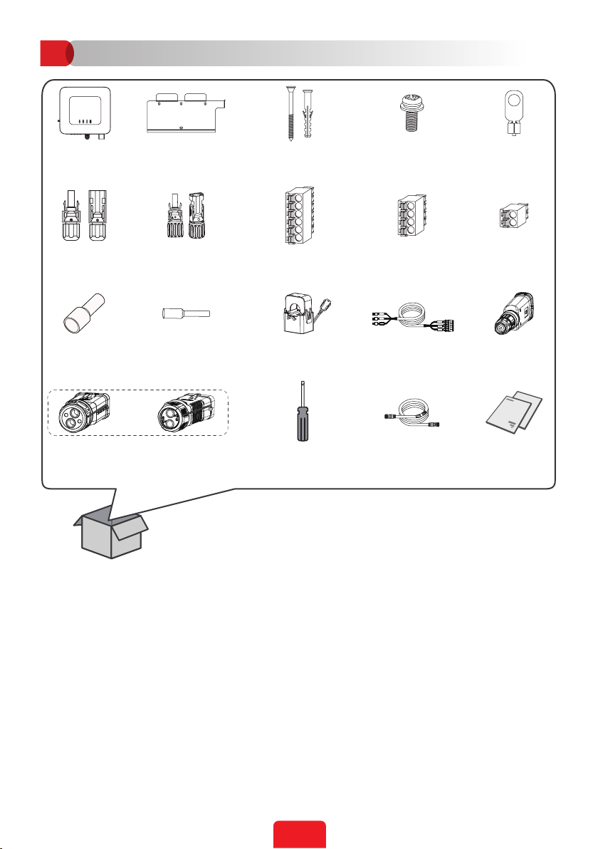
• Check the deliverables for correct model, complete contents, and intact appearance. Contact
the manufacturer if any damage is found or any component is missing.
• Use insulating tools and wear personal protective equipment when operating the equipment
electronic components to protect the inverter from damage. The manufacturer shall not be
liable for any damage caused by static electricity.
•
manual. The manufacturer shall not be liable for equipment damage or personal injury if you
do not follow the instructions.

2
EN
6. All labels and warning marks should be visible after the installation. Do not scrawl, damage,
or cover any label on the device.
7. Do not touch the running equipment to avoid being hurt as its temperature may exceed 60°C.
Do not install the equipment at a place within children's reach.
8.
covered under the warranty.
9. If there is any radio or wireless communication equipment below 30MHz near the inverter,
you have to:
• Install the inverter at least 30m far away from the wireless equipment.
•
cable of the inverter.
10.
HIGH VOLTAGE HAZARD.
Disconnect all incoming power
working on it.
are completely discharged.
Read through the guide before
working on this device.
PPE before any operations.
High-temperature hazard. Do
not touch the product under
operation to avoid being burnt.
Grounding point. Indicates the
position for connecting the PE cable.
CE marking Do not dispose of the inverter
as household waste.Discard the
product in compliance with local
laws and regulations, or send it back
to the manufacturer.
5min

3
Check before Power-on
No. Check Item
1
operate.
2The PE, DC input, AC output, and communication cables are connected correctly and
securely.
3 Cable ties are intact, routed properly and evenly.
4 Unused ports and terminals are sealed.
5The voltage and frequency at the connection point meet the inverter grid connection
requirements.
EU Declaration of Conformity
Viessmann Climate Solutions SE hereby declares that the inverter with wireless communication
modules sold in the European market meets the requirements of the following directives:
• Radio Equipment Directive 2014/53/EU (RED)
• Restrictions of Hazardous Substances Directive 2011/65/EU and (EU) 2015/863 (RoHS)
•
• Registration, Evaluation, Authorization and Restriction of Chemicals (EC) No 1907/2006 (REACH)
Viessmann Climate Solutions SE hereby declares that the inverter without wireless
communication modules sold in the European market meets the requirements of the following
directives:
• Electromagnetic compatibility Directive 2014/30/EU (EMC)
• Electrical Apparatus Low Voltage Directive 2014/35/EU (LVD)
• Restrictions of Hazardous Substances Directive 2011/65/EU and (EU) 2015/863 (RoHS)
•
• Registration, Evaluation, Authorization and Restriction of Chemicals (EC) No 1907/2006 (REACH)
Battery safety:
1. The battery used with the inverter shall be approved by the inverter manufacturer. The
2. Before installations, read through the corresponding battery's user manual to learn about
the product and the precautions. Strictly follow its requirements.
3. If the battery discharged completely, please charge it in strict accordance with the
corresponding model's User Manual.
4.
5. If the battery cannot start properly, contact the after-sales service as soon as possible.
Otherwise, the battery will be damaged permanently.
6. Measure the DC cable using the multimeter to avoid reverse polarity connection. Also, the
voltage should be under the permissible range.
7. To avoid damage the inverter, do not connect one battery pack to multi inverters.

4
EN
LED Indicators
Indicator Status Description
The inverter is power on and in the standby mode.
The inverter is starting up and in the self-check mode.
modes.
BACK-UP output overload.
A fault has occurred.
The grid is normal and the inverter is in grid-tied mode.
The monitoring module of the inverter is resetting.
The inverter fails to connect with the communication terminal
device.
Faults between the communication terminal device and Server.
The monitoring of the inverter operates well.
The monitoring module of the inverter has not been started
yet.

5
Introduction
02 Product Introduction
Parts
[1]: Viessmann Hybrid Inverter 6.0F-3, Viessmann Hybrid Inverter 8.0F-3: MPPT x 2; Viessmann
Hybrid Inverter 10.0F-3, Viessmann Hybrid Inverter 12.0F-3, Viessmann Hybrid Inverter 15.0F-3:
MPPT x 3.
[2]: Viessmann Hybrid Inverter 12.0F-3 and Viessmann Hybrid Inverter 15.0F-3 are available with
optional fans.
Dimensions
1. System Indicator 2. Battery SOC Indicator 3. PE Terminal
4. Mounting Plate 5. Heat Sink 6. DC Switch
7. Ventilation Valve 8. PV Input Terminal[1] 9. Battery Terminal
10. Communication Port 11. Communication Module Port 12. AC Terminal
13. Heat Sink[2]

6
Inverter Installation
03
N = Quantity depends on the inverter model.
CT-L1
CT-L2
CT-L3 CT-L1
CT-L2
CT-L3
x 1 x 1 x 4
x 18
x 1
x 2 x 1
x 1
or
x 3x 12
x 1 x N
x 1 x 1
x 1x 1
x 1
x 1 x 1

7
Space Requirements
Children No Touch
0%~100%RH
IP66
ALT: 4000m
≥200mm
≥300mm
≥200mm
≥300mm
≥500mm

8
4 5
1 2 3
M6
3N·m
Angle Requirements
Installing the Inverter
D: 80mm
Only for Australia.

9
Electrical Connection
04
PE Cable
6
M5
1.2~2N·m
L=L1+(1~2)mm L1
1
23
M5
1.5~2N·m
Copper, S = 6mm2

10
DC Cable (PV)
Click
7~8mm
7~8mm
4mm2≤S≤6mm2
Click Click
≤1000V
1
23
4
2
3
4
1
1
2
3
1
1
45
2
2
2

11
Battery Cable (BAT)
1
2
1
1
45
2
2
3
1
2
3
4
5
1
2
3
4
5
7~8mm
7~8mm
Click Click
≤720V
10mm2≤S≤16mm2
Click

12
AC Cable (ON-GRID&BACK-UP)
Type One
12
2
1
L1
L2
L3
N
PE
LL
BACK-UP: 75mm
ON-GRID: 55mm
34
3
1
4
2
2
3
1
1 3
2
: S=6mm2

13
Type Two
12
2
1
L1
L2
L3
N
PE
34
1 3
2
3
1
3
1
4
2
LL
BACK-UP: 75mm
ON-GRID: 55mm
2
: S=6mm2

14
3
1
2
2
1
1
2
1
5
4
3
Communication Connection
05
Communication Cable (PIN terminal)
6~8mm
25mm
0.2mm2≤S ≤0.3mm2
4

15
5
6
12345
12
78910 11
18
1314151617
19
20 21
22
23
24
6
1 2 3 4 5
12
78910 11
18
13 14 15 16 17
19
20
23
24 21
22
CT
1: CT1 +
2: CT1 -
3: CT2 +
4: CT2 -
5: CT3 +
6: CT3 -
GEN
(Optional)
11: DO+
12: DO-
DRED/RCR (Optional)
13: DRM0 or REF_1
14: RefGen or REF_2
15: DRM4/8 or DI_4
16: DRM3/7 or DI_3
17: DRM2/6 or DI_2
18: DRM1/5 or DI_1
Meter
(Optional)
19: RS485B
20: RS485A
BMS EN
(Optional)
21: EN-
22: EN+
23: RS485B
24: RS485A
LOAD CNTL
(Optional)
9: DO+
10: DO-
RSD
(Optional)
7: RSD+
8: RSD-
6
1
2
3

16
CT Cable
1
CT-L2
CT-L3
CT-L1
CT-L2
CT-L3
2
CT-L1
CT-L2
CT-L3
CT-L1
CT-L2
CT-L3
CT-L1
CT-L2
CT-L3
CT-L1
CT-L2
CT-L3
CT-L1
CT-L2
CT-L3
3
CT1
CT2
CT3
L1
L2
L3
N
KL
CT connecting cable: 15m
(Optional) CT
extension cable: 10m

17
Communication Cable (RJ45 network cable)
3
1 2 3 4 5 6 7 8 PIN Color Parallel1&EMS
Port (PAR-
1&EMS485)
Parallel2 Port
(PAR-2) BMS
(CAN)
1 RS485A (EMS) - -
2 Orange RS485B (EMS) - -
3 - - -
4 Blue CANH (Reserved) CANH (Reserved) CANH
5 CANL (Reserved) CANL (Reserved) CANL
6 Green GND (Reserved) GND (Reserved) -
7 BUS1 (Reserved) BUS1 (Reserved) -
8Brown BUS2 (Reserved) BUS2 (Reserved) -
1
2
2
1
1
2
1
5
4
3
4

18
Communication Module
1
2
5
Parallel2 Port (PAR-2
Reserved)
BMS (CAN)
CAN
PAR-1 &
EMS485 PAR-2
Parallel1&EMS Port
(PAR-1&EMS485)
1
2
3
6

19
Power On and O
06
Power On
Power O
Turn on
For Australia only.
32
1
4
5
PV string
PV string
Battery breaker
Battery BACK-UP loads
AC breaker
ON-GRID
BACK-UP
Utility Meter Utility grid
Inverter
1 2 3 4
1 2 3 4
This manual suits for next models
4
Table of contents
Other Viessmann Inverter manuals
Popular Inverter manuals by other brands

Huawei
Huawei SUN2000-8KTL-M0 user manual

Hypontech
Hypontech HPT Series user manual

Master Battery
Master Battery MasterPower Beta Series Installation and operation manual

Mitsubishi Electric
Mitsubishi Electric FR-D700 Series instruction manual

WARRIOR
WARRIOR DG6700 owner's manual

Generac Power Systems
Generac Power Systems MMG120 Specifications

SMA
SMA SUNNY BOY STORAGE 3.7 operating manual

SEW-Eurodrive
SEW-Eurodrive MOVIDRIVE system operating instructions

Trotec
Trotec AIROZON 60000 Original instructions

Hitachi
Hitachi L100-004HFE instruction manual

SEW-Eurodrive
SEW-Eurodrive Movidrive MDX61B manual

Power Electronics
Power Electronics SD 500 Series Getting started manual