Viessmann Vitocell 140-E Operating instructions
Installation and service
instructions
for contractors
VIESMANN
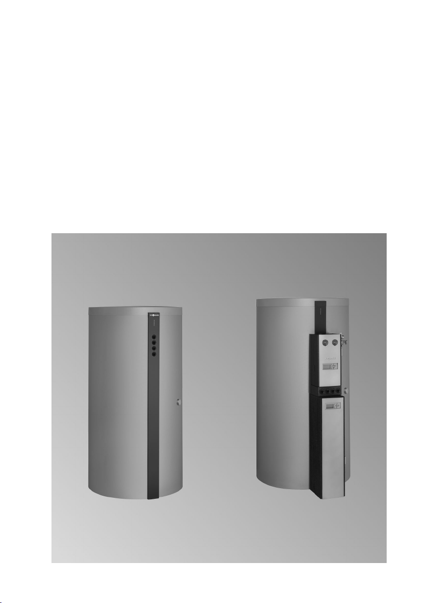
Vitocell 140-E/160-E
Type SEIA
Type SESA
Solar buffer cylinder
For applicability, see the last page
VITOCELL 140-E/160-E
5517 155 GB 3/2014 Please keep safe.
2
Please follow these safety instructions closely to prevent accidents and mate-
rial losses.
Safety instructions explained
Danger
This symbol warns against the
risk of injury.
!Please note
This symbol warns against the
risk of material losses and envi-
ronmental pollution.
Note
Details identified by the word "Note" con-
tain additional information.
Target group
These instructions are exclusively inten-
ded for qualified contractors.
■ Work on electrical equipment must
only be carried out by a qualified elec-
trician.
■ The system must be commissioned by
the system installer or a qualified per-
son authorised by the installer.
Regulations
Observe the following when working on
this system:
■ National installation regulations
■ Statutory regulations regarding the
prevention of accidents
■ Statutory regulations regarding envi-
ronmental protection
■ The Code of Practice of relevant trade
associations
■ All current safety regulations as
defined by DIN, EN, DVGW, VDE and
all locally applicable standards
aÖNORM, EN and ÖVE
cSEV, SUVA, SVTI and SWKI
If you smell flue gas
Danger
Flue gas can lead to life threat-
ening poisoning.
■ Shut down the heating system.
■ Ventilate the installation site.
■ Close all doors in the living
space.
Flue systems and combustion air
Ensure that flue systems are clear and
cannot be sealed, for instance due to
accumulation of condensate or other
causes. Ensure a sufficient supply of
combustion air.
Instruct system users that subsequent
modifications to the building characteris-
tics are not permissible (e.g. cable/pipe-
work routing, cladding or partitions).
Safety instructions
Safety instructions
5517 155 GB

3
Danger
Leaking or blocked flue systems,
or an insufficient supply of com-
bustion air can cause life threat-
ening poisoning from carbon
monoxide in the flue gas.
Ensure the flue system is in
proper working order. Apertures
for supplying combustion air
must be non-closable.
Extractors
Operating appliances that extract air to
the outside (cooker hoods, extractors, air
conditioning units, etc.) can create neg-
ative pressure. If the boiler is operated at
the same time, this can lead to reverse
flow of the flue gas.
Danger
The simultaneous operation of
the boiler and appliances that
extract air to the outside can
result in life threatening poison-
ing due to reverse flow of the flue
gas.
Fit an interlock circuit or take suit-
able steps to ensure a sufficient
supply of combustion air.
Working on the system
■ Isolate the system from the power sup-
ply (e.g. by removing the separate fuse
or by means of a mains isolator) and
check that it is no longer 'live'.
■ Safeguard the system against recon-
nection.
Danger
Hot surfaces can cause burns.
■ Before maintenance or service
work, switch OFF the appli-
ance and let it cool down.
■ Never touch hot surfaces on
the boiler, burner, flue system
or pipework.
!Please note
Electronic assemblies can be
damaged by electrostatic dis-
charge.
Before beginning work, touch
earthed objects, such as heating
or water pipes, to discharge static
loads.
Repair work
!Please note
Repairing components that fulfil a
safety function can compromise
the safe operation of the sys-
tem.
Faulty components must be
replaced with original Viessmann
spare parts.
Safety instructions
Safety instructions (cont.)
5517 155 GB

4
Auxiliary components, spare and
wearing parts
!Please note
Spare and wearing parts that
have not been tested together
with the system can compromise
its function. Installing non-author-
ised components and making
non-approved modifications or
conversions can compromise
safety and may invalidate the
warranty.
For replacements, use only orig-
inal spare parts supplied or
approved by Viessmann.
Safety instructions
Safety instructions (cont.)
5517 155 GB

5
Service instructions
Intended use....................................................................................................... 6
Installation instructions
Installation information
Product information.............................................................................................. 7
Installation sequence
Vitocell without fitted Solar-Divicon...................................................................... 11
Vitocell with fitted Solar-Divicon........................................................................... 21
Installing the cylinder temperature sensor............................................................ 40
Connections on the heating water side................................................................ 41
Service instructions
Commissioning, inspection, maintenance
Further details regarding the individual steps....................................................... 42
Parts lists
Cylinder assembly................................................................................................ 43
Thermal insulation assembly................................................................................ 45
Connection set assembly (accessories)............................................................... 47
Commissioning/service reports........................................................................ 49
Product characteristics..................................................................................... 50
Accessories
Immersion heater specification............................................................................. 51
Certificates
Declaration of conformity...................................................................................... 52
Index
Index
5517 155 GB

6
The appliance is only intended to be
installed and operated in sealed unven-
ted systems that comply with EN 12828 /
DIN 1988, or solar thermal systems that
comply with EN 12977, with due atten-
tion paid to the associated installation,
service and operating instructions. DHW
cylinders are only designed to store and
heat water of potable water quality. Heat-
ing water buffer cylinders are only
designed to hold fill water of potable
water quality. Only operate solar collec-
tors with the heat transfer medium
approved by the manufacturer.
Intended use presupposes that a fixed
installation in conjunction with permissi-
ble, system-specific components has
been carried out.
Commercial or industrial usage for a pur-
pose other than heating the building or
DHW shall be deemed inappropriate.
Any usage beyond this must be
approved by the manufacturer for the
individual case.
Incorrect usage or operation of the appli-
ance (e.g. the appliance being opened
by the system user) is prohibited and
results in an exclusion of liability.
Incorrect usage also occurs if the com-
ponents in the system are modified from
their intended use (e.g. through direct
DHW heating in the collector).
Adhere to statutory regulations, espe-
cially concerning the hygiene of potable
water.
Intended use
Intended use
5517 155 GB

7
Vitocell 140-E, type SEIA and Vitocell 160-E, type SESA (750 and
950 l)
■ Solar buffer cylinder made from steel,
for central heating backup in combina-
tion with heat pumps, solar thermal
systems, oil/gas boilers, solid fuel boil-
ers and/or electric heating with an
immersion heater.
■ With the option to fit a Solar-Divicon,
type PS10 (pump station for a collector
circuit).
■ Suitable for systems to EN 12828 and
DIN 4753
■Vitocell 160-E, type SESA also
includes a stratification system for
solar heating
Installation information
Product information
5517 155 GB
Installation
8
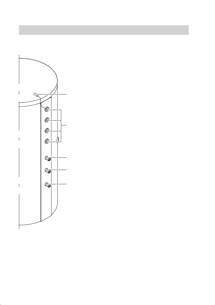
Connections
A
B
C
D
E
Front view without fitted Solar-Divicon
(accessories)
AThermometer sensor retainer
BThermometer
(up to 4 pce)
CHeating water flow G 1
DReturn stratification G 1
EHeating water return G 1
Installation information
Product information (cont.)
5517 155 GB
9
N
F
P
B
A
C
E
G
L
D
H
K
M
O
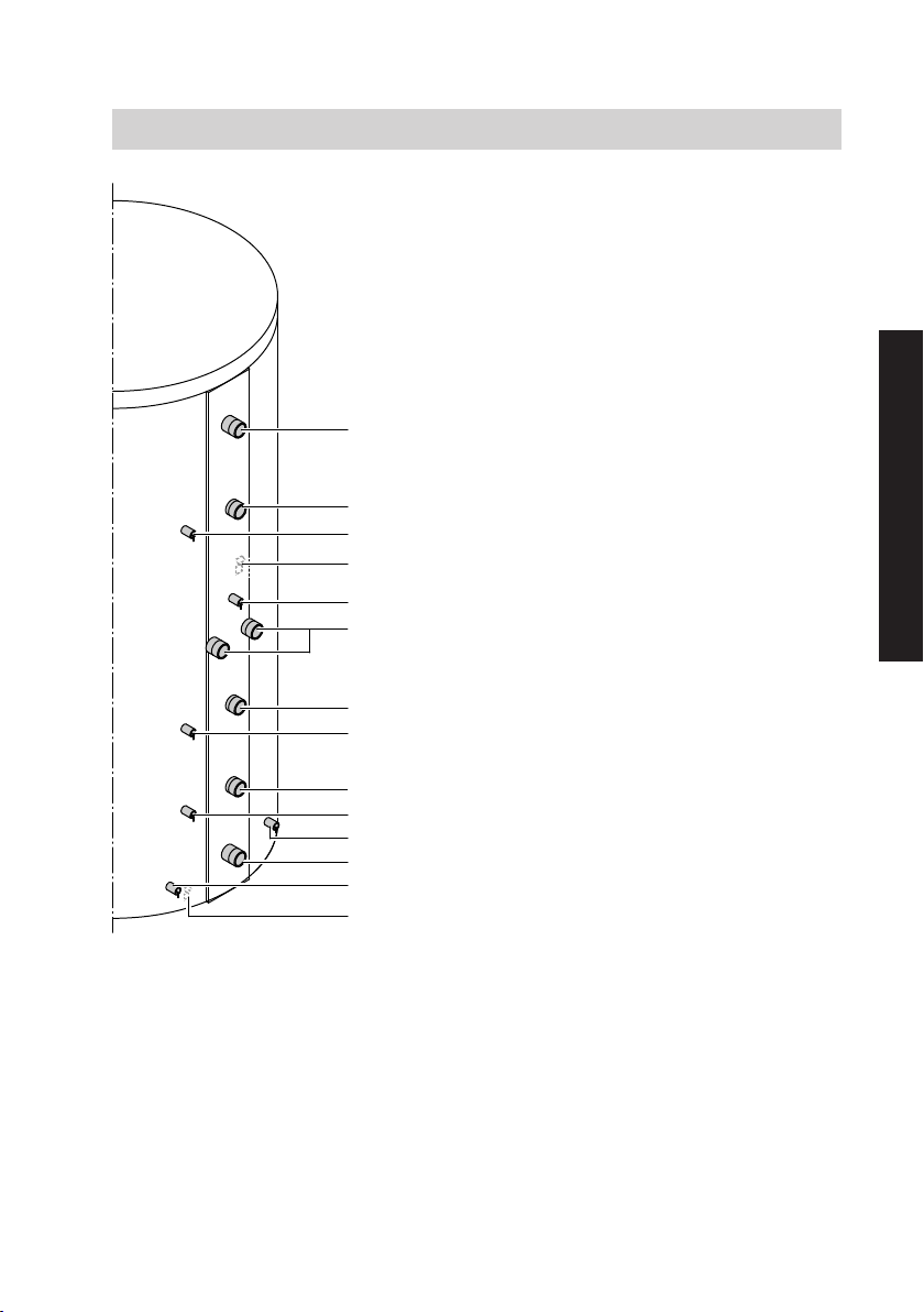
Back
AHeating water flow 1 to the heating
circuits/air vent valve
BHeating water flow 2
from the heat source
CSensor well
for cylinder temperature sensor
DThermometer sensor retainer
ESensor well 2
for cylinder temperature sensor and
thermometer sensor
FHeating water flow 3/heating water
return
GHeating water return 2
from the heating circuits
HSensor well 3
for cylinder temperature sensor and
thermometer sensor
KHeating water return 3
LSensor well 4
for cylinder temperature sensor
MSolar heating water flow / air vent
valve (if Solar-Divicon accessory is
fitted: at the front of the heating
water buffer cylinder)
NHeating water return 4 to the heat
source / drain outlet
OSolar heating water return (if Solar-
Divicon accessory is fitted: at the
front of the heating water buffer cyl-
inder)
PThermometer sensor retainer
Installation information
Product information (cont.)
5517 155 GB
Installation

10
Siting information
!Please note
To prevent material losses, install
the heating water buffer cylinder
in a room free from the risk of frost
and draughts.
Otherwise the heating water buf-
fer cylinder must be drained
when not in use and there is a risk
of frost.
■ Provide adequate clearance from the
wall so that the temperature controller
can be operated (if installed).
■ Placing the heating water buffer cylin-
der on a plinth will make the room eas-
ier to clean.
Installing the Vitocell with an immersion heater
a
a
Immersion heater installation
instructions
Maintain the minimum clearance.
Cylinder capacity Output
Immersion heater
Dim. a
750 and 950 l 6 kW
12 kW
min. 500 mm
min. 700 mm
Note
The unheated length of any threaded
immersion heater installed on site must
be at least 100 mm.
Installation information
Product information (cont.)
5517 155 GB
Other manuals for Vitocell 140-E
4
This manual suits for next models
3
Table of contents
Other Viessmann Inverter manuals


