Viessmann CS User manual

GB
General notice (liability): the details of this technical documents serve for description. Consents regarding the availability of certain features or
regarding a certain purpose always require a special written agreement.
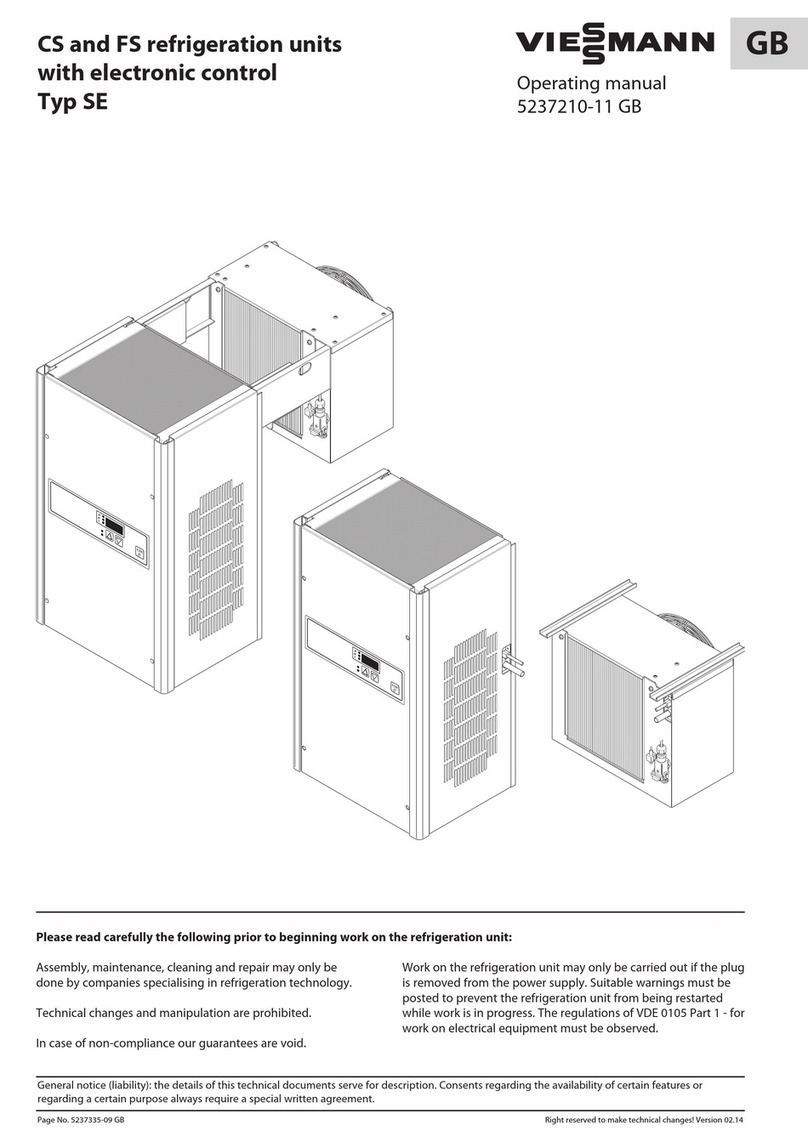
CS and FS Refrigeration units
with SD Control unit
Installation and
Operating Instructions
00111850-03 GB
Page No. 1-GB We reserve the right to make technical changes! Status as of 02.14
Ensure compliance with the following instructions prior to beginning work on the Refrigeration unit:
Wall-hanging unit
Split unit
Installation, cleaning maintenance and repair work must be per-
formed only by a refrigeration specialist company.
Technical modifications and manipulation are prohibited.
Non-compliance will result in forfeiture of all warranty claims.
Work on the Refrigeration unit is authorised only when the mains
plug has been removed. The Refrigeration unit must be pro-
tected against unauthorized activation by appropriate means
(e.s. warning sign). The directives, VDE 0105 Part 1, for working
on electrical equipment must be complied with.

GB
General notice (liability): the details of this technical documents serve for description. Consents regarding the availability of certain features or
regarding a certain purpose always require a special written agreement.
Table of contents
Page No. 2-GB Content We reserve the right to make technical changes!
1. Description
1.1 Deep-freeze unit
FS 0900, FS 1200, FS 1400, FS 1800, FS 2400
1.2 Refrigeration unit
CS 0500, CS 0900, CS 1300, CS 2000, CS 2800
2. General information
2.1 Excepts from our Warranty conditions
2.2 Standards and regulations
2.3 Requirements for the installation room
2.4 Transport
2.5 Delivery condition for Wall-hanging units
2.6 Delivery condition for Split units
2.7 Unpacking and handling
2.8 Energy conservation
3. Cleaning and maintenance of the Refrigeration unit
3.1 Disposal of cooling agent
4. Installation of a Wall-hanging unit in a
Viessmann cold storage cell
4.1 Connecting a remote control unit (SD Control)
5. Installation of a Split unit in a
Viessmann cold storage cell
5.1 Installation of the condenser unit
5.1.1 Drill template for attachment of the large condenser unit
5.1.2 Drill template for attachment of the small condenser unit
5.2 Installation of the evaporator unit
5.2.1 Drill template for attachment of the large evaporator unit
5.2.2 Drill template for attachment of the small evaporator unit
5.3 Layout and installation of the pipelines
5.4 Layout and installation of the electrical lines
5.5 Installation of the defrost water drain hose
6. Drainage of defrost water
7. Coldroom electrical power supply
7.1 Connecting the door contact switch
7.1.1 Refrigeration unit with electronic SD Control unit
7.2 Connecting the Fault report contact
7.3 Power supply connection and commissioning
7.3.1 CEE mains plug
(only on Refrigeration units FS 1800, FS 2400)
8. Operating the SD Control unit
8.1 Normal operation
8.2 Parameter entry
8.2.1 Entry of nominal temperatures
8.2.2 Entry of defrosting times
8.2.3 Selection of coldroom humidity
8.2.4 Selection of language for display indications
8.2.5 Password and keyboard lock
8.2.6 Access levels for the System operator
8.3 Fault report
8.4 Decommissioning of the Refrigeration unit
8.5 Operating mode parameters
(for refrigeration specialist company)
8.5.1 Parameter list
8.5.2 Description of operating modes and the
respective parameters
9. Drawings
9.1 Refrigeration circulation schematic
9.2 Electrical circuit diagram for CS 0500 SD to CS 2800
SD, FS 0900 SD, FS 1200 SD, FS 1400 SD
9.3 Electrical circuit diagram for FS 1800 SD and
FS 2400 SD
10. Faults
10.1 Malfunction codes
10.2 Emergency operation
10.3 Fault rectification
11. Favourable storage specifications
11.1 Cold storage
11.2 Deep-freeze storage

GB
General notice (liability): the details of this technical documents serve for description. Consents regarding the availability of certain features or
regarding a certain purpose always require a special written agreement.
Page No. 3-GB 1 - 2.3 We reserve the right to make technical changes!
1. Description
The units are designed for the prescribed temperature
anges. If they are operated outside the prescribed tempe-
rature range for several days, the possibility of a serious
defect on the refrigerating unit cannot be discounted.
1.1 Deep-freeze unit
FS 0900, FS 1200, FS 1400, FS 1800, FS 2400
The units are designed for the cooling of rooms, in which
goods are stored at temperatures of -25°C to -1°C.
1.2 Refrigeration unit
CS 0500, CS 0900, CS 1300, CS 2000, CS 2800
The units are designed for the cooling of rooms, in which
goods are stored at temperatures of -5°C to +19°C.
2. General information
2.1 Excepts from our Warranty conditions
The warranty is valid for 1 year. The period of entitlement
begins on the day of delivery, which must be verified by
the Bill of delivery or Invoice. Within the period of warran-
ty, functional defects attributed to faulty design or materi-
al defect will be rectified at no charge.
Claims in excess of these, in particular those related to
consequential damage, are excluded.
We will accept no liability for damages, which result from
improper or unauthorised utilisation, faulty installation
or commissioning on the part of the customer or a third-
party, natural wear and tear, faulty or negligent handling,
chemical, electro-chemical or electrical influences, as long
as the fault cannot be attributed back to actions taken
on our part, non- compliance with Installation, Operating
and Maintenance Instructions, improper modifications or
repair work on the part of the customer or a third-party,
as well as the influence of replacement parts from third-
party origin.
Warranty entitlement is forfeited, as well, if the refrigera-
tion circuit has been opened by unauthorised personnel,
access has been made to the system assembly, or the
serial number has been changed or made unrecognisa-
ble.
2.2 Standards and regulations
The Wall-hanging unit has been built and inspected
according to the standards and regulations valid at the
time of manufacture.
It complies with the
EMC Directive 2004/108/EC,
machinery directive 2006/42/EG.
The unit has been inspected at the factory for refrigerati-
on circulation leakage and for function.
2.3 Requirements for installation area / Intended use
The Refrigeration unit must not be assembled outdoors.
The Refrigeration unit must be setup to ensure the free
intake and discharge of air. In the event the use of air
ducts is unavoidable, project planning must be made by
a refrigeration specialist company.
Sufficient free space must be provided for in front of
the Refrigeration unit intake and discharge openings in
order to warrant a good air flow:
- minimum 250 mm in front of all intake and
exhaust openings
If it is not possible to maintain this clearance, then suf-
ficient air flow must be warranted by means of suitable
measures (air deflector, air ducts, additional ventilators).
The unit must not be deployed in areas where strong
strong magnetic interfering impulses are anticipated or
in the vicinity of transmitting antennas.
The unit must not be setup in an explosive atmosphere!
GB
General notice (liability): the details of this technical documents serve for description. Consents regarding the availability of certain features or
regarding a certain purpose always require a special written agreement.
Page No. 4-GB 2.3 - 2.8 We reserve the right to make technical changes!
The unit must not be setup in a fire-endangered opera-
ting site!
According to DIN VDE 0100-482 (VDE 0100 Part 482),
this is:
1997-08
Rooms or locations in rooms or in the open, in which, with
respect to the local and operational circumstances, the
danger exists that highly inflammable materials could
come so close to the electrical equipment at such hazar-
dous levels that the higher temperatures of this electrical
equipment or electric arcing create a fire hazard.
This includes: Working, dry and storage rooms or sections
of rooms, as well as similar outside locations, such as
paper, textile and wood processing operations, hay, straw,
jute or flax storage yards.
- According to BGR 500, chapter 2.35 or local regulations
for operation and maintenance. (qualified staff)
2.4 Transport
The Refrigeration unit must be transported in its opera-
ting position due to oil in the compressor. For possible
further transport, only the original packaging may be
used.
2.5 Delivery condition for Wall-hanging units
The Wall-hanging unit is delivered in a carton, operatio-
nally ready and wired for immediate plug-in.
2.6 Delivery condition for Split units
The Split unit is delivered in a carton and wired for
immediate plug-in.
2.7 Unpacking and handling
- Prior to and during the unpacking of the Refrigeration
unit, a visual inspection should be made in to deter-
mine whether possible damage has occurred during
transport.
- Please pay attention to loose parts, dents, scratches
visible oil loss, etc.
- Before disposing of the packing material, a check of it
should be made to ensure that no loose parts are hid-
den in it.
- In order to process warranty claims, please provide an
exact description of the deficiency (with picture if pos-
sible), as well as information as to unit model designa-
tion and serial number.
- In order to protect the unit from damage, it must only
be transported in its operating position. It must be
ensured that the evaporator and condenser units have
not been damaged. Non-compliance will result in for-
feiture of the warranty entitlement.
2.8 Energy conservation
Direct sunlight will raise the consumption of electricity.
Avoid any unnecessary or too lengthy opening of the
door.
Monitor the storage temperature.
Regularly clean the Refrigeration unit. A clean unit saves
energy and has a longer service life.
Observe cleaning intervals (see Chapter “Cleaning and
maintenance of the Refrigeration unit”). Regular mainte-
nance increases the service life.

GB
General notice (liability): the details of this technical documents serve for description. Consents regarding the availability of certain features or
regarding a certain purpose always require a special written agreement.
Page No. 5-GB 3 - 3.1 We reserve the right to make technical changes!
3. Cleaning and maintenance of the Refrigeration unit
Attention!
The mains plug must be removed from the socket and
protected against re-insertion for all cleaning and
maintenance work.
Following commissioning, the Refrigeration unit should
bechecked periodically and cleaned as necessary. The time
span between the checks or cleaning should be establis-
hed based on the level of contamination.
The time interval for cleaning is dependent on on the
ambient conditions. Yet, at least one maintenance inspec-
tion should be performed annually.
The evaporator unit should be cleaned, either with a soft
cleaning brush, with compressed air or, in case of with
heavy grease deposits, with an industrial cleaner. Do not
use any sharp or sharp edged object for cleaning. It must
also be ensured that the thin lamella fins are not bent or
damaged during the cleaning process.
Do not spray the unit with water or steam!
3.1 Disposal of cooling agent
If the Refrigeration unit must be replaced with a new unit,
ensure that the Refrigeration unit pipelines are not dama-
ged to the point that the cooling agent leaks out.
Defective Refrigeration units or extracted cooling agent
must be disposed of in a manner compatible to the envi-
ronment and in accordance with applicable regulations.

GB
General notice (liability): the details of this technical documents serve for description. Consents regarding the availability of certain features or
regarding a certain purpose always require a special written agreement.
Page No. 6-GB 4We reserve the right to make technical changes!
4. Installation of a Wall-hanging unit in a
Viessmann cold storage cell
Sufficient free space must be provided for in front of the
Refrigeration unit intake and discharge openings in order to
warrant a good air flow:
A wall element can be delivered by us with the respective
cut-outs and bore holes for installation in the cold storage
cell.
Otherwise, the required bores holes and cut-outs should
be made on location by a refrigeration technician using
installation templates or the dimensional drawings.
The cutting edges and bore holes must be protected
against corrosion with zinc primer paint.
Attention!
The electrical power supply should first be connected
at commissioning after installation has been completed
-Risk of life!
Loosen the holding angle from the unit.

GB
General notice (liability): the details of this technical documents serve for description. Consents regarding the availability of certain features or
regarding a certain purpose always require a special written agreement.
Page No. 7-GB 4We reserve the right to make technical changes!
Hang the unit on the storage cell wall while pushing against
it from the outside.
Slide the holding angle against the inside cell wall and tigh-
ten it securely with one or two bolts.
Insert the enclosed blind-rivet nuts (P) in the bore holes
(d = 8 mm).

GB
General notice (liability): the details of this technical documents serve for description. Consents regarding the availability of certain features or
regarding a certain purpose always require a special written agreement.
Page No. 8-GB 4We reserve the right to make technical changes!
Bolt the enclosed holding angle (M) to the unit housing
together with storage cell wall (M4 x 15 bolts (H) for attach-
ment to the blind-rivet nuts (P) in the storage cell wall and
hexagonal nuts (L) with washers (K) for attachment to the
housing).
Loosen the locking screws (4 ea.) on the front access cover.
Be careful to ensure that the serrated lock washers are not
displaced.
Slide the front access cover slightly upwards and pull for-
ward to remove.
Slide the enclosed plastic collar (D) over the defrost water
drain hose (B).

GB
General notice (liability): the details of this technical documents serve for description. Consents regarding the availability of certain features or
regarding a certain purpose always require a special written agreement.
Page No. 9-GB 4 We reserve the right to make technical changes!
For units with electric defrosting, insert the defrost water
drain heating into the defrost water drain hose (B); pull the
defrost water drain hose (B) as straight as possible to ease
the insertion process.
Siphon (C) only for deep-freezing units.
Guide the defrost water drain hose (B) through the bore
hole (G, ø 31 mm) in the cell wall (F) from the inside.
Lubricant can be used if necessary.
Connect the defrost water drain hose (B) to the drain port
(E) on the evaporator condensate tray.
Insert the defrost water drain into the defrost water tray on
Refrigeration and Deep-freeze units.
Cover the cut-out (G) for the defrost water drain hose (B)
with the plastic collar (D).
Fill out the area above the Refrigeration unit hanging rail
with the enclosed Armaflex hoses (N) as sealing material.
Remount the front access cover, securing it to the unit with
the enclosed sheet-metal screws ST 3.9 x 19 and serrated
lock washers A 4.3.
Attention!
If cable ducts or the like are to be installed next to the
Refrigeration unit, a space of 30mm must be maintained
between the cable duct and the unit to ensure that the
unit sidewall can be removed for maintenance work.
A
B
N
N

GB
General notice (liability): the details of this technical documents serve for description. Consents regarding the availability of certain features or
regarding a certain purpose always require a special written agreement.
Page No. 10-GB 4.1 We reserve the right to make technic changes!
4.1 Connecting a remote control unit (SD Control)
In case the unit has been ordered with a remote control,
attach the remote control at the designated location and
plug in the adapter via the 10-pole flat ribbon cable to the
back side of the control unit. Attach the adapter with the
enclosed cable binders to the rear wall of the control hou-
sing. (with bus control, see Bus control manual)

GB
General notice (liability): the details of this technical documents serve for description. Consents regarding the availability of certain features or
regarding a certain purpose always require a special written agreement.
Page No. 11-GB 5 - 5.1 We reserve the right to make technical changes!
5. Installation of a Split unit in a
Viessmann cold storage cell
5.1 Installation of the condenser unit
The condenser unit is installed outside the cold storage
cell. The length of the electric lines on the condenser unit,
including plug, is 15 m. This is also the maximum distance
between the condenser unit and the evaporator unit.
The minimum distance to the room ceiling must be at least
250 mm in order to warrant a good air flow.
Attention!
This minimum distance must be checked prior to instal-
lation of the condenser unit!
Attention!
Assembly and installation of the Refrigeration unit in
the split version must be carried out by a refrigeration
specialist company according to applicable refrigerati-
on-related regulations!
Loosen the locking screws (4 ea.) on the front access cover.
Remove the front access cover by pulling upwards and for-
ward.
Attach the condenser unit to the wall through the prescri-
bed bore holes on the back-side of the unit, using the
attachment materials included in the enclosed accessory kit.

GB
General notice (liability): the details of this technical documents serve for description. Consents regarding the availability of certain features or
regarding a certain purpose always require a special written agreement.
Page No. 12-GB 5.1.1 - 5.1.2 We reserve the right to make technical changes!
5.1.1 Drill template for attachment of the large condenser unit
(CS 2000; CS 2800; FS 1400; FS 1800; FS 2400)
Distance to wall - 60 mm.
5.1.2 Drill template for attachment of the small condenser unit
(CS 0900; CS 1300; FS 0900; FS 1200)
Distance to wall - 60 mm.
Anschlüsse für Kälte-
mittel und Elektro-
leitungen zum Verdampfer
Wand
Decke
min. 60 mm
zwei Bohrungen
mit 12 mm
12 mm
min.
250 mm
94 mm
420 mm
240 mm
600 mm
390 mm
850 mm

GB
General notice (liability): the details of this technical documents serve for description. Consents regarding the availability of certain features or
regarding a certain purpose always require a special written agreement.
Page No. 13-GB 5.2 - 5.2.2 We reserve the right to make technical changes!
5.2 Installation of the evaporator unit
The evaporator unit is mounted to the ceiling on the inside of the
cold storage cell.
Four bore holes should be made in the cell ceiling according to
dimensional drawings 2.2.1 and 2.2.2.
Protect the cutting edges against rust.
Attach the evaporator unit to the U-profile on the cell ceiling with
the enclosed plastic locking screws.
5.2.1 Drill template for attachment of the large evaporator unit
(CS 2000; CS 2800; FS 1400; FS 1800; FS 2400)
Distance to wall 140 mm with a wall thickness of 150 mm. Distance
to wall 230 mm with a wall thickness of 60 mm.
5.2.2 Drill template for attachment of the small evaporator unit
(CS 0900; CS 1300; FS 0900; FS 1200)
Distance to wall 165 mm with a wall thickness of 150 mm.
Distance to wall 255 mm with a wall thickness of 60 mm.
min. 15 min. 15
255 mm
381 mm
ø 11 mm
Abstand zur Wand 165 - 255 mm
Ausblasöffnung
Ansaugöffnung
Wand
Wand
Draufsicht Decke

GB
General notice (liability): the details of this technical documents serve for description. Consents regarding the availability of certain features or
regarding a certain purpose always require a special written agreement.
Page No. 14-GB 5.3 - 5.4 We reserve the right to make technical changes!
5.3 Layout and installation of the pipelines
Solder the solder connections (P and Q) on the Refrigeration
unit to the solder connections on the evaporator unit by
means of a suitable copper pipeline.
Check all solder points for leak-tightness!
The length of the pipeline must not exceed15 m!
Pipe diameter in mm
Unit CS 900 CS 1300 CS 2000 CS 2800
Fluid line (P) 6 6 6 10
Suction line (Q) 10 12 12 16
5.4 Layout and installation of the electrical lines
For practical purposes, the Layout and installation of the
electrical lines takes place along the pipeline.
Insert the electrical connector plug into the appropriate
plug adapter on the Refrigeration unit circuit board.
Attention!
The electrical power supply should first be connected
at commissioning - Risk of life!
Pipe diameter in mm
Unit FS 900 FS 1200 FS 1400 FS 1800 FS 2400
Fluid line (P) 6 6 10 10 10
Suction line (Q) 12 12 16 16 16

GB
General notice (liability): the details of this technical documents serve for description. Consents regarding the availability of certain features or
regarding a certain purpose always require a special written agreement.
Page No. 15-GB 5.5 We reserve the right to make technical changes!
5.5 Installation of the defrost water drain hose
Slide the enclosed plastic collar (D) over the defrost water
drain hose (B).
Insert the defrost water drain heating (A) into the defrost
water drain hose (B), pulling the defrost water drain hose (B)
as straight as possible to ease the insertionprocess.
Guide the defrost water drain hose (B) through the bore
hole G, ø 31 mm) in the cell wall (F) from the inside.
Lubricant can be used if necessary.
Connect the defrost water drain hose (B) to the drain port
(E) on the evaporator condensate tray.
Cover the cut-out (G) for the defrost water drain hose (B)
with the plastic collar (D).
See the separate defrost water drain installation instructions
for all Split units.

GB
General notice (liability): the details of this technical documents serve for description. Consents regarding the availability of certain features or
regarding a certain purpose always require a special written agreement.
Page No. 16-GB 6 - 7.1.1 We reserve the right to make technical changes!
6. Drainage of defrost water
We recommend using the defrost water drain accessory
pack, available as an option, for an optimal drainage of
defrost water accumulation.
The accessory pack can be used for all Viessmann FS- and
CS- series Refrigeration units.
7. Coldroom electrical power supply
A 4-pole socket outlet is located on the intake-side of the
Refrigeration evaporator unit for the electrical power supply
to the loads attached to the coldroom, with a total power
capacity of max. 250 Watts (lighting, door frame heating).
The door contact switch can also be connected to this
socket outlet.
7.1 Connecting the door contact switch
The evaporator ventilator should be switched off when the
cold storage cell is opened. For this reason, we recommend
the installation of an potential-free door contact switch
(switching capacity 230VAC, min. 0.5 A).
Connection takes place via the 4-pole socket outlet moun-
ted on the intake-side of the evaporator unit.
In its delivered condition, the unit is functionally ready for
service without an external door contact switch.
The door contact switch is not included within the scope of
delivery of the unit.
7.1.1 Refrigeration unit with electronic SD Control unit
If a door contact switch is connected to the unit, then the
control unit parameter P29 must be changed to “1” (see
8.5.1, Parameter list).
L1
22
33
11
PEPE
N
PE
230VAC
max. 250 VA
Türkontaktschalter
gez. bei geöffneter Tür
4-pol. Steckverbindung
am Aggregat von Kühlzelle

GB
General notice (liability): the details of this technical documents serve for description. Consents regarding the availability of certain features or
regarding a certain purpose always require a special written agreement.
Page No. 17-GB 7.2 - 7.3 We reserve the right to make technical changes!
7.2 Connecting the Fault report contact
The electronic SD Control unit is outfitted with a potential-
free Fault report contact for connection to the on-site Fault
reporting equipment (max. 10A, 230VAC).
In the event of a fault, contacts C and NC are closed.
The connection is located on the circuit board (plug connec-
tor A3 orange).
7.3 Power supply connection and commissioning
Attention!
The electrical power supply should first be connected at
commissioning - Risk of life!
Work on the power supply connector and protection
devices must be carried out by a specialist company, in
accordance with IEC 364, local regulations and the connec-
tion conditions of the respective energy supply company!
Insert the mains plug into the approved and properly
grounded socket (230 VAC or 400 VAC, 50 Hz, 16A slow-
blow).
Electronic SD Control unit
The unit starts after the Control unit self-test function and
afterrun-out of an approx. 3 minute delay time (adjustable
via parameter P34). During the initial switch-on, this time
delay can be bypassed by switching the unit off, then by
switching it subsequently back on by means of the Start/
Stop key. The “Stop-Start-Enter” key must be actuated for
approx. 3 sec. in order to switch off the unit.
C NC NO
A3

GB
General notice (liability): the details of this technical documents serve for description. Consents regarding the availability of certain features or
regarding a certain purpose always require a special written agreement.
Page No. 18-GB 7.3.1 We reserve the right to make technical changes!
7.3.1 CEE mains plug
(only on Refrigeration units FS 1800 and FS 2400)
Loosen the locking screws (4 ea.) on the front access cover.
Be careful to ensure that the serrated lock washers are not
displaced.
Slide the front access cover slightly upwards and pull for-
wardto remove.
Loosen the lateral inside positioned attachments screws on
the right side-section, slide the side-section (Y) upwards and
remove.
Guide the main connector cable with CEE mains plug (Q) to
the outside. Re-hang side-section (Y), slide downwards and
secure with the attachment screws.
Insert the CEE mains plug into the on-site CEE socket
(3+N+PE, AC 400V, 16A, 50 Hz).
Remount the front access cover, securing it to the unit with
the enclosed sheet-metal screws ST 3.9 x 19 and serrated
lock washers A 4.3.

GB
General notice (liability): the details of this technical documents serve for description. Consents regarding the availability of certain features or
regarding a certain purpose always require a special written agreement.
Page No. 19-GB 8 - 8.1 We reserve the right to make technical changes!
8.1 Normal operation
The current coldroom temperature is indicated in the dis-
play. If one of the keys [ ] or [ ] is actuated, the current
nominal temperature appears. The right decimal point indi-
cation illuminates correspondingly.
If one of the keys [ ] or [ ] is actuated for 5 sec., the nomi-
nal temperature can be changed within the released tem-
perature range via keys [ ] or [ ]. (A change in the nominal
value in the manner described is possible only if the pass-
word protection has been removed, see 8.2.5).
If a new key actuation does not take place within 10 sec., the
new nominal value will be saved and the room temperature
will be indicated.
During the system start process, “Sd” and the software sta-
tus will appear in the display (e.g. “5.4”). In this manner, the
control unit software status can be determined.
If both keys [ ] and [ ] are depressed in a switched-off
state and the “Stop-Start-Enter” key is subsequently actu-
ated, then the system will be started with a forced defrost.
If keys [ ] and [ ] are not actuated during switch-on, then
the system will be started in the cooling mode. A previously
initiated defrost mode will be switched off, if applicable.
Never depress the keys with a pointed object (e.g. ballpoint
pen, screw driver or the like).
Display indications during operation:
Function German English French
Standby OFF OFF OFF
defrost Abt. dEF. DEg.
Indication with key actuation
and active key-lock Bo.L Bo.L Bo.L
Fault (x=Error No.) F.x E.x d.x
Version indication “Sd” “5.4”
8. Operating the SD Control unit

GB
General notice (liability): the details of this technical documents serve for description. Consents regarding the availability of certain features or
regarding a certain purpose always require a special written agreement.
Page No. 20-GB 8.2 - 8.2.2 We reserve the right to make technical changes!
8.2 Parameter entry
If both keys [ ] and [ ] are actuated simultaneous-
ly during operation, the Parameter function will be
accessed.
In this function, the nominal temperature and the
defrost times can be entered or changed. Likewise, the
mode of operation of the evaporator fan for high or low
air humidity in the coldroom can be set.
The designation of the selected parameter appears in
the display, while the yellow LED in the “Stop-Start-
Enter” key illuminates; in this case, the “Stop-Start” func-
tion is switched off.
By actuating the “Stop-Start-Enter” key, the display can
be switched between the parameter designation and
the parameter value.
By using the keys [ ] or [ ], the parameter address or
the parameter value can be changed within the prescri-
bed limits.
The parameters can be protected against unauthorised
changes by means of a password (P07 <> x2). In order to
access the parameters released by the System operator
in this case, the following procedure should be under-
taken:
Depress both keys [ ] and [ ] simultaneously during
operation, P01 appears in the display, the yellow LED in
the “Stop- Start-Enter” key illuminates simultaneously.
Depress the “Stop-Start-Enter” key
- 1 is indicated in the display.
Select the value 5 with the keys [ ] or [ ].
Depress the “Stop-Start-Enter” key
- P01 is indicated in the display.
By using the keys [ ] or [ ], the desired parameters P02
- P09, or P02 - P23 as appropriate (see 8.2.6 ), can now
be selected.
Parameter entry will be ended automatically after 10
sec. if a key has not been actuated. It will also be ended
if the value 0 is entered into parameter P01.
8.2.1 Entry of nominal temperatures
Following entry of the password, select parameter P02
(indication in display SL.t.), depress the Enter key, the
current nominal temperature is indicated in °C. It can be
changed within the range released for respective unit
model (normal cooler -5°C to 20°C; deep -freezer -25°C
to -5°C) by using the keys [ ] or [ ].
8.2.2 Entry of defrosting times
Defrosting according to specified cycle times
- Entry of the defrost pause:
Following entry of the password, select parameter P03
(indication in display Ab.h.), depress the Enter key, the
current defrost pause time will be indicated in hours. It
can be changed within the range of 1 to 24 hrs. by using
the keys [ ] or [ ].
The defrost pause should shortened if the air humidity
in the coldroom is so high that the evaporator is is com-
pletely iced over.
Defrosting at definite specified times
If a DCF radio receiver is connected to the control unit,
12 switching points can be entered into the parameters
P12 to P23, at which times the defrosting process will be
started. For this, the parameter P30 must be set accor-
dingly (only by a refrigeration specialist company).
Following entry of the password, select parameters P12
to P23 (indication in display t.01 .. t.12), depress the
Enter key, the current switching point for starting the
defrosting process will be indicated in format hh.m(x10).
It can be changed within the range of 00.0 to 23.5 or set
to “OFF” by using the keys [ ] or [ ]. The numbers in
front of the decimal point indicate the hours, while the
digit after the decimal point indicates the minutes in
values of ten.
This manual suits for next models
11
Table of contents
Other Viessmann Refrigerator manuals

Viessmann
Viessmann FS0900 User manual

Viessmann
Viessmann FG1 PI 67 205 User manual

Viessmann
Viessmann Tecto MD5 User manual

Viessmann
Viessmann TECTOPROMO MD1 EUROCLASSIC User manual

Viessmann
Viessmann Tecto SV4 PI User manual

Viessmann
Viessmann TK-70 User manual

Viessmann
Viessmann norpe ECOCOOLER User manual

Viessmann
Viessmann TectoCell Standard Plus 80 User manual

Viessmann
Viessmann FS Series User manual

Viessmann
Viessmann Tecto FI2 84 PI User manual