manuals.online logo
Brands
  1. Home
  2. •
  3. Brands
  4. •
  5. Viessmann
  6. •
  7. Relay
  8. •
  9. Viessmann 5228 User manual

Viessmann 5228 User manual

Gebrauchsanleitung
Manual
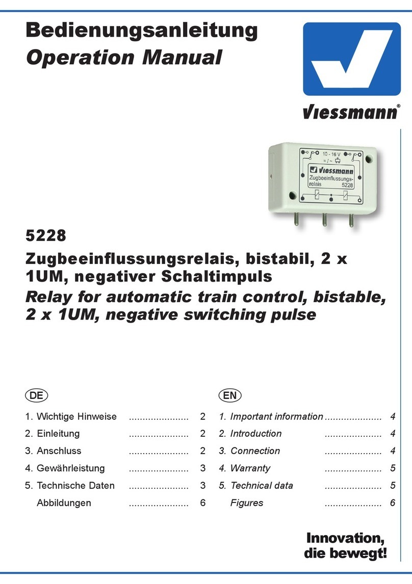
5228
Zugbeeinflussungsrelais
1 x 2 UM
Relay for automatic train control
1 x 2 change-over contacts
1. Wichtige Hinweise ...................................... 2
2. Einführung / Eigenschaften ........................ 2
3. Anschluss ................................................... 2
4. Technische Daten ...................................... 4
1. Important Information ................................. 2
2. Introduction / Properties ............................. 2
3. Connection ................................................ 2
4. Technical Data ........................................... 4
2
viessmann
5228
10 - 16 V
= / ~
Zugbeeinflussungs-
relais
Steuerstromkreis
Schaltstromkreis
Control circuit
Switched circuit
DE EN
Fig. 1
Abb. 1
1. Wichtige Hinweise
Lesen Sie vor der ersten Benutzung des Pro-
duktes bzw. dessen Einbau diese Anleitung kom-
plett und aufmerksam durch. Bewahren Sie diese
Anleitung auf. Sie ist Teil des Produktes.
Das Produkt richtig verwenden
Das Produkt darf ausschließlich dieser Anleitung
gemäß verwendet werden. Dieses Steuermodul
ist bestimmt
– zum Einbau in Modelleisenbahnanlagen,
– zum Anschluss an die Viessmann Signal-
steuermodule 5224 oder 5229,
– zum Betrieb in trockenen Räumen.
Jeder darüber hinausgehende Gebrauch gilt als
nicht bestimmungsgemäß. Für daraus resultie-
rende Schäden haftet der Hersteller nicht.
2. Einführung / Eigenschaften
Das Zugbeeinussungsrelais erweitert die Steuer-
module um die automatische Zugbeeinussung.
Es kann den Fahrstrom an Gleis und / oder Ober-
leitung bei „Halt“ zeigendem Signal mittels zwei-
poligem Umschalter abschalten. Im Digitalbetrieb
kann es auch auf das Bremsmodul 5232 (Märklin-
Motorola) oder einen DCC-Bremsgenerator um-
schalten.
Elektronisches Relais
Das Modul 5228 ist auch unabhängig von Signal-
modulen für verschiedenste Schaltaufgaben ein-
setzbar.Als Steuereingänge fungieren die drei
Kontaktstifte an der linken Seite. Kabel lassen
sich dort mit den Muffen (Art.Nr. 6879 - 6887) an-
schließen. Das Schaltschema ist auf dem Modul
aufgedruckt. Abbildung 1 zeigt schematisch den
Anschluss.
3. Anschluss
Stecken Sie das Zugbeeinussungsrelais, wie in
den folgenden Abbildungen gezeigt, an das Sig-
nalmodul an. Die Kontaktstifte passen genau in
die Buchsen der Signalmodule. Dadurch wird die
elektrische Verbindung hergestellt und das Modul
außerdem mechanisch festgehalten.
Schließen Sie das Modul gemäß der Abbildungen
an. Beachten Sie jeweils auch die Hinweise in den
Anleitungen zu den Signal- bzw. Bremsmodulen.
1. Important Information
Please read this manual prior to rst use of the
product resp. its installation! Keep this manual.
It is part of the product.
Intended use
This product must only be used as required in
this manual. This model of a signal is intended
– for installation in model railroad layouts,
– for connection to the Viessmann signal
modules 5224 or 5229,
– for operation in a dry area.
Using the product for any other purpose is not
approved and is considered incorrect. The
manufacturer cannot be held responsible for any
damage resulting from the improper use of this
product.
2. Introduction / Properties
The relay extends the signal control modules by
adding the possibility to stop the train. It interrupts
the track power (separate for track and / or cat-
enary) of a “stop” signal by double-pole change-
over contacts. In digital use, it can control the
brake module 5232 (Mot.) or a brake generator
for DCC.
3. Connection
Connect the relay to the module as shown in the
following gures. The contact pins t into the plugs
of the signal modules. This ensures the electrical
connection and keeps the relay mechanically con-
nected to the module.
Make the electrical wiring as shown in the follow-
ing gures. Notice the hints in the manuals of the
signal- and brake modules.
3
viessmann
5228
10 - 16 V
= / ~
Zugbeeinflussungs-
relais
viessmann
5224
Steuermodul für
Lichtsignale
Signal(e)
Sh1COM Hp2
Hp1Hp0
Brem-
sen
Signal-
Bus
Signal-
Bus
rt bn
16 V ~/
Digital
16 V ~/
Digital
rt bn
▼
▼
Hp Vr
1
2
1
21
2
rot
rot
braun
rot
rot
rot
rot
Optional:
Oberleitung
brown
/ red
red
red
red
/ red
/ red
/ Catenary
16 V ~ / = /
digital
Fahrtrichtung / Route
Fig. 2
Abb. 2
viessmann
5228
10 - 16 V
= / ~
Zugbeeinflussungs-
relais
viessmann
5224
Steuermodul für
Lichtsignale
Signal(e)
Sh1COM Hp2
Hp1Hp0
Brem-
sen
Signal-
Bus
Signal-
Bus
rt bn
16 V ~/
Digital
16 V ~/
Digital
rt bn
▼
▼
Hp Vr
1
2
1
21
2
viessmann
Digital-
Bremsmodul
5232
SBF
rt bn
STOP
Märklin-Motorola
Fahrtrichtung / Route
Digital
rot
rot
rot
rot
braun
braun
bremsen fahren
rot
/ red
red
red
/ red
/ brown
brown
/ brake / proceed
red
viessmann
5228
10 - 16 V
= / ~
Zugbeeinflussungs-
relais
viessmann
Multiplexer 5229
für Lichtsignale
ON
12345678
WnP
LSB
Sh1 Hp2
Hp1Hp0
Bremsen
Signal-
Bus
Signal-
Bus
rt bn
16 V ~/ Dig.
16 V ~/ Dig.
rt bn
Hp
Vr
COM
Signale
5229:
Anschluss und Verdrahtung
erfolgen wie beim Modul 5224.
Connection and wiring are
similar to module 5224.
Fig. 3
Abb. 3
Dieses Produkt ist kein Spielzeug. Nicht geeignet für Kinder unter 14
Jahren! Anleitung aufbewahren!
This product is not a toy. Not suitable for children under 14 years!
Keep these instructions!
Ce produit n’est pas un jouet. Ne convient pas aux enfants de moins
de 14 ans ! Conservez ce mode d’emploi !
Dit produkt is geen speelgoed. Niet geschikt voor kinderen onder 14
jaar! Gebruiksaanwijzing bewaren!
Questo prodotto non è un giocattolo. Non adatto a bambini al di sotto
dei 14 anni! Conservare instruzioni per l’uso!
Esto no es un juguete. No recomendado para menores de 14 años!
Conserva las instrucciones de servicio!
4
Modellspielwaren GmbH
viessmann
5228
10 - 16 V
= / ~
Zugbeeinflussungs-
relais
viessmann
5224
Steuermodul für
Lichtsignale
Signal(e)
Sh1COM Hp2
Hp1Hp0
Brem-
sen
Signal-
Bus
Signal-
Bus
rt bn
16 V ~/
Digital
16 V ~/
Digital
rt bn
▼
▼
Hp Vr
1
2
1
21
2
DCC
Fahrtrichtung / Route
Digital
rot rot
braun
rot
rot
braun
blau
rot
braun
braun
Brems-
generator
brown
/ red red
red
red
brown
blue
/ red
/ brown
brown
Brake
generator
Fig. 4
Abb. 4
7/2009 Ko
Stand 01
Sach-Nr. 92352
Made in Europe
7. Technical Data
Operating voltage: 10 - 16 V AC/DC
Load per set of contacts: 2 A
Environmental Care
At the end of life this product is not to be disposed
of as household garbage but has to be returned to
a collection point for the recycling of electrical and
electronic products.
The symbol of the garbage bin on the product, the
manual and the package serves as a reminder.
All materials can be recycled as indicated.
7. Technische Daten
Betriebsspannung: 10 - 16 V =/~
Belastbarkeit je Umschaltkontakt: 2 A
Umweltschutzhinweis
Dieses Produkt darf am Ende seiner Lebensdauer
nicht über den normalen Hausmüll entsorgt wer-
den. Es muss an einem Sammelpunkt für das Re-
cycling von elektrischen und elektronischen Gerä-
ten abgegeben werden.
Das Mülleimer-Symbol auf dem Produkt, der Be-
dienungsanleitung oder der Verpackung weist da-
rauf hin. Die Werkstoffe sind gemäß ihrer Kenn-
zeichnung wiederverwertbar.

Other Viessmann Relay manuals

Viessmann 5551 User manual

Viessmann

Viessmann 5551 User manual

Viessmann 5207 User manual

Viessmann

Viessmann 5207 User manual

Viessmann 5227 User manual

Viessmann

Viessmann 5227 User manual

Viessmann 5226 User manual

Viessmann

Viessmann 5226 User manual

Viessmann 5551 User manual

Viessmann

Viessmann 5551 User manual

Viessmann 5551 User manual

Viessmann

Viessmann 5551 User manual

Viessmann 5228 User manual

Viessmann

Viessmann 5228 User manual

Viessmann 5552 User manual

Viessmann

Viessmann 5552 User manual

Viessmann 5227 User manual

Viessmann

Viessmann 5227 User manual

Popular Relay manuals by other brands

Eaton PKZM4-40 Instruction leaflet

Eaton

Eaton PKZM4-40 Instruction leaflet

Siemens SIRIUS 3RS1000 operating instructions

Siemens

Siemens SIRIUS 3RS1000 operating instructions

HANYOUNG NUX SSR-2C Series instruction manual

HANYOUNG NUX

HANYOUNG NUX SSR-2C Series instruction manual

Kieback&Peter BMA0600 instruction manual

Kieback&Peter

Kieback&Peter BMA0600 instruction manual

Abus Terxon SX installation instructions

Abus

Abus Terxon SX installation instructions

red lion PM-50 installation guide

red lion

red lion PM-50 installation guide

Kyongbo Electronics GDR-JD01 user manual

Kyongbo Electronics

Kyongbo Electronics GDR-JD01 user manual

Circutor RGU-10A instruction manual

Circutor

Circutor RGU-10A instruction manual

DOLD VARIMETER RCM Installations

DOLD

DOLD VARIMETER RCM Installations

MRS Toggle Relay M3 12 V operating instructions

MRS

MRS Toggle Relay M3 12 V operating instructions

Pilz PNOZ e7p operating instructions

Pilz

Pilz PNOZ e7p operating instructions

ABB BL-1 quick start guide

ABB

ABB BL-1 quick start guide

Pickering 42-323 user manual

Pickering

Pickering 42-323 user manual

Dantel 46032-15 Installation & operation manual

Dantel

Dantel 46032-15 Installation & operation manual

Arcteq AQ F205 instruction manual

Arcteq

Arcteq AQ F205 instruction manual

Boutronic JGA2011 manual

Boutronic

Boutronic JGA2011 manual

ZEWOTHERM 1x installation instructions

ZEWOTHERM

ZEWOTHERM 1x installation instructions

FANOX SIL-A user manual

FANOX

FANOX SIL-A user manual

manuals.online logo
manuals.online logoBrands
  • About & Mission
  • Contact us
  • Privacy Policy
  • Terms and Conditions

Copyright 2025 Manuals.Online. All Rights Reserved.