manuals.online logo
Brands
  1. Home
  2. •
  3. Brands
  4. •
  5. Viessmann
  6. •
  7. Toy
  8. •
  9. Viessmann 1898 User manual

Viessmann 1898 User manual

TIPP: Powermodul, Art. 5215
- Verhindert Flackern bei Wechselstrom.
- Annähernd doppelte Helligkeit gegenüber reinem
Wechselstrombetrieb.
TIP: Power module, item 5215
- Offers flicker-free lighting when using AC power.
- Nearly double brightness is possible.
Made in Europe
Zugzielanzeiger mit
LED-Beleuchtung
Destination display with
LED lighting
Bedienungsanleitung
Operation Manual
DE
1. Wichtige Hinweise
Bitte lesen Sie vor der ersten Anwendung des Produktes bzw.
dessen Einbau diese Bedienungsanleitung aufmerksam durch.
Bewahren Sie diese auf, sie ist Teil des Produktes.
1.1 Sicherheitshinweise
Vorsicht:
Verletzungsgefahr!
Aufgrund der detaillierten Abbildung des Originals bzw. der
vorgesehenen Verwendung kann das Produkt Spitzen, Kan-
ten und abbruchgefährdete Teile aufweisen. Für die Montage
sind Werkzeuge nötig.
Stromschlaggefahr!
Die Anschlussdrähte niemals in eine Steckdose einführen!
Verwendetes Versorgungsgerät (Transformator, Netzteil)
regelmäßig auf Schäden überprüfen. Bei Schäden am Ver
-
sorgungsgerät dieses keinesfalls benutzen!
Alle Anschluss- und Montagearbeiten nur bei abgeschalteter
Betriebsspannung durchführen!
Ausschließlich nach VDE/EN gefertigte Modellbahntransfor-
matoren verwenden!
Stromquellen unbedingt so absichern, dass es bei einem
Kurzschluss nicht zum Kabelbrand kommen kann.
1.2 Das Produkt richtig verwenden
Dieses Produkt ist bestimmt:
- Zum Einbau in Modelleisenbahnanlagen und Dioramen.
- Zum Anschluss an einen Modellbahntransformator
(z. B. Art. 5200) bzw. an eine Modellbahnsteuerung mit
zugelassener Betriebsspannung.
- Zum Betrieb in trockenen Räumen.
Jeder darüber hinausgehende Gebrauch gilt als nicht bestim-
mungsgemäß. Für daraus resultierende Schäden haftet der
Hersteller nicht.
1.3 Packungsinhalt überprüfen
Kontrollieren Sie den Lieferumfang auf Vollständigkeit:
- Gehäuse mit LED und Anschlusskabeln
- 2 Dekopapiere
- 2 Halterungen
- 2 Masten
- Anleitung
1
brown shrink
yellow shrink
Diode und Widerstand nicht abschneiden.
Never cut o diode and resistor.
Diode
Widerstand
resistor
Sekundär
0-10-16 V~
16 V
Primär
230 V~
Gefertigt nach
VDE 0570
EN 61558
Lichttransformator
5200
Nur für trockene Räume
Primär 230V 50 - 60 Hz
Sekundär max. 3,25 A52 VA
ta 25°CIP 40
10 V
0 V
z. B. / e. g. 5200
viessmann
Powermodul 5215
T
E
ge bn
Braune Massebuchsen
nicht koppeln !
max. 24 V~
rt bn
zu den Decodern
5215
gelb
braun
16 V~
yellow
/brown
16 V~
Abb. 6
Abb. 7
Diode
diode
Widerstand
resistor
brauner Schrumpfschlauch
gelber Schrumpfschlauch
Fig. 6
Fig. 7
89491
Stand 03/sw
05/2023
Ho/Kf
4
DC voltage: Connect the diode (red part with black marking)
with the positive pole of the power supply.
AC voltage: Operation with AC voltage could cause some
ickering. We recommend to use the Viessmann power module,
item 5215 (g. 5) which is sucient for ca. 100 LEDs. Connect
the cable to the diode with the brown output socket (g. 4).
5. Technical data
Operating voltage: 10 – 16 V AC ~
(with and without item 5215, power module)
14 – 24 V DC =
13 – 24 V digital signal
Operating current: ca. 10 mA
10 – 16 V AC ~
(mit und ohne Art. 5215, Powermodul)
(with and without item 5215, power module)
14 – 24 V DC =
13 – 24 V Digitalsignal
digital signal
–
+
Abb. 4 Fig. 4 Abb. 5 Fig. 5
Viessmann
Modelltec
hnik GmbH
Bahnhofstraße 2a
D - 35116 Hatzfeld-Reddighausen
[email protected]
+49 6452 9340-0
www.viessmann-modell.de
FR
Points de collecte sur www.quefairedemesdechets.fr
À DÉPOSER
EN MAGASIN À DÉPOSER
EN DÉCHÈTERIE
OU
Cet modéle
se recycle
FR
Entsorgen Sie dieses Produkt nicht über den (unsortierten)
Hausmüll, sondern führen Sie es der Wiederverwertung zu.
Do not dispose of this product through (unsorted) domestic
waste, supply it to recycling instead.
Subject to change without prior notice. No liability for mistakes and printing
errors.
You will nd the latest version of the manual on the Viessmann website using
the item number.
Änderungen vorbehalten. Keine Haftung für Druckfehler und Irrtümer.
Die aktuelle Version der Anleitung finden Sie auf der Viessmann Homepage
unter der Artikelnummer.
Modellbauartikel, kein Spielzeug! Nicht geeignet für
Kinder unter 14 Jahren! Anleitung aufbewahren!
Model building item, not a toy! Not suitable for children
under the age of 14 years! Keep these instructions!
Ce n’est pas un jouet! Ne convient pas aux enfants de
moins de 14 ans! Conservez cette notice d’instructions!
Não é um brinquedo! Não aconselhável para menores
de 14 anos! Conservar o manual de instruções!
Modelbouwartikel, geen speelgoed! Niet geschikt voor
kinderen onder 14 jaar! Gebruiksaanwijzing bewaren!
Articolo di modellismo, non è un giocattolo! Non adat-
to a bambini al di sotto dei 14 anni! Conservare istruzioni
per l’uso!
Artículo para modelismo ¡No es un juguete! No reco-
mendado para menores de 14 años! Conserva las inst-
rucciones de servicio!
DE
EN
FR
NL
IT
ES
PT
yellow shrink
gelber Schrumpfschlauch
brown shrink
brauner Schrumpfschlauch
ENDE
2. Einleitung
Dieser Zugzielanzeiger erzeugt durch die SMD-LED ein zum
Modell passendes Licht. Stromaufnahme und Wärmeentwicklung
sind sehr gering. Die Lebensdauer der LED ist praktisch unbe-
grenzt, sodass ein Wechsel des Leuchtmittels entfällt.
3. Einbau
- Den Zugzielanzeiger vorsichtig aus der Verpackung nehmen.
- Vor dem Einbau auf Funktion prüfen.
- Die Dekobögen sind austauschbar. Zum Öffnen der Scheiben
verwenden Sie eine Nadel oder ähnliches und hebeln die
Scheiben durch Einführen der Nadel in die Einkerbung
heraus (Abb. 1). Ein Programm zum Erstellen von personali-
sierten Dekobögen finden Sie auf der Viessmann Homepage
unter der Artikelnummer.
- Am Einbauort wird eventuell zur Durchführung der Kabel eine
Bohrung Ø 2 mm benötigt (Abb. 2).
- Die Anschlusskabel von außen durch die Bohrung hindurch-
führen und den Zugzielanzeiger befestigen, z. B. mit einem
handelsüblichen Sekundenkleber. Bei der Montage des Zug-
zielanzeigers mit Mast, kürzen Sie die Masten (Abb. 3) auf
die gewünschte Länge und befestigen den Zugzielanzeiger
mit den Masten am Einbauort (Abb. 4 und Abb. 5).
Um etwaige Wartungsarbeiten durchführen zu können, sollten
die Anschlusskabel idealerweise mit einer Kabelschleife von
mindestens 2 – 3 cm Länge verlegt werden.
Vorsicht:
Widerstand und Diode an den Enden der Anschlussdrähte
sind für die Funktion erforderlich. Keinesfalls entfernen
(Abb. 6)! Widerstände nicht mit Isolationsmaterial umhüllen,
da sonst keine ausreichende Kühlung möglich ist!
4. Anschluss
Schließen Sie den Zugzielanzeiger an den Lichtausgang eines
Modellbahntransformators (z. B. Art. 5200) an (Abb. 7).
Gleichspannung: Verbinden Sie die Diode (rotes Bauteil mit
schwarzer Markierung) mit dem Plus-Pol des Netzteils, den
Widerstand mit dem Minus-Pol.
Wechselspannung: Bei Betrieb mit Wechselspannung kann
es zu leichtem Flackern kommen. Daher empfehlen wir den
Betrieb mit dem Viessmann-Powermodul, Art. 5215 (Abb. 7).
Ein Powermodul ist ausreichend für ca. 100 LED-Leuchten oder
-Strahler. Verbinden Sie das Anschlusskabel mit der Diode mit
der braunen Ausgangsbuchse, das Anschlusskabel mit dem
Widerstand mit der roten Anschlussbuchse (Abb. 7).
5. Technische Daten
Betriebsspannung: 10 – 16 V AC ~
(mit und ohne Art. 5215, Powermodul)
14 – 24 V DC =
13 – 24 V Digitalsignal
Stromaufnahme: ca. 10 mA
1. Important information
Please read this manual completely and attentively before using
the product for the rst time. Keep this manual. It is part of the
product.
1.1 Safety instructions
Caution:
Risk of injury!
Due to the detailed reproduction of the original and the
intended use, this product can have peaks, edges and break-
able parts. For installation tools are required.
Electrical hazard!
Never put the connecting wires into a power socket!
Regularly examine the transformer for damage.
In case of any damage, do not use the transformer.
Make sure that the power supply is switched off when
you mount the device and connect the cables!
Only use VDE/EN tested special model train transformers
for the power supply!
The power sources must be protected to prevent the risk of
burning cables.
1.2 Using the product for its correct purpose
This product is intended:
- For installation in model train layouts and dioramas.
- For connection to an authorized model train transformer
(e. g. item 5200) or a digital command station.
- For operation in dry rooms only.
Using the product for any other purpose is not approved and is
considered incorrect. The manufacturer is not responsible for
any damage resulting from the improper use of this product.
1.3 Checking the package contents
Check the contents of the package for completeness:
- Chassis with LED and connection cables
- 2 decorative papers
- 2 brackets
- 2 masts
- Manual
2. Introduction
This destination display produces the light by SMD-LEDs which
is suitable to the model. Low heat build-up and power input.
Nearly unlimited lifetime of the LED, so no more change is
required.
3. Mounting
- Remove the destination display carefully from the package.
- Check function before mounting.
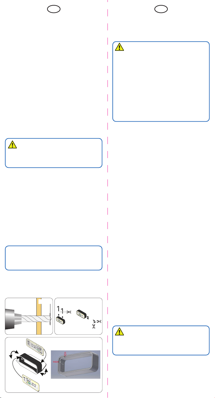
- The decoration sheets are exchangeable. To open the panes
use a needle or similar, insert it into the notch and lever
them out (fig. 1) You will find a programme for the creation of
personalized decoration sheets on the Viessmann homepage
under the article number.
- At the mounting place, a Ø 2 mm hole may be required for
the cable pass through (fig. 2).
- Put the cables from outside through the drill hole and fix
the destination display, e. g. with a commercial glue. When
mounting the destination display with mast, cut the masts
(fig. 3) back to the required length and mount the destination
display with the masts to the desired location (fig. 4 and 5).
In order to carry out possible maintenance work, the connection
cables should be installed with a cable loop of min. 2 – 3 cm
length.
Caution:
Resistor and diode at the cables are needed for proper func-
tion. Never cut them off (fig. 4)! Never cover resistor or diode
with insulation material, because they have to be cooled by
surrounding air!
4. Connection
Connect the destination display to the light output of a model
train transformer (e. g. item 5200) or power supply as shown
in g. 5.
32
Abb. 1 Fig. 1
Abb. 2
Ø 2 mm
Fig. 2 Abb. 3 Fig. 3

Other Viessmann Toy manuals

Viessmann Vollmer 43864 User guide

Viessmann

Viessmann Vollmer 43864 User guide

Viessmann 4172 User manual

Viessmann

Viessmann 4172 User manual

Viessmann 5547 User manual

Viessmann

Viessmann 5547 User manual

Viessmann 9010 User manual

Viessmann

Viessmann 9010 User manual

Viessmann 1500 User manual

Viessmann

Viessmann 1500 User manual

Viessmann 6338 User manual

Viessmann

Viessmann 6338 User manual

Viessmann 5090 User manual

Viessmann

Viessmann 5090 User manual

Viessmann 9500 User manual

Viessmann

Viessmann 9500 User manual

Viessmann 1591 User manual

Viessmann

Viessmann 1591 User manual

Viessmann Vollmer 43600 User guide

Viessmann

Viessmann Vollmer 43600 User guide

Viessmann 1500 User manual

Viessmann

Viessmann 1500 User manual

Viessmann 5231 User manual

Viessmann

Viessmann 5231 User manual

Viessmann 5052 User manual

Viessmann

Viessmann 5052 User manual

Viessmann 5107 User manual

Viessmann

Viessmann 5107 User manual

Viessmann Vollmer 42540 User guide

Viessmann

Viessmann Vollmer 42540 User guide

Viessmann 3043 User manual

Viessmann

Viessmann 3043 User manual

Viessmann 4751 User manual

Viessmann

Viessmann 4751 User manual

Viessmann 6049 User manual

Viessmann

Viessmann 6049 User manual

Viessmann kibri 15010 User guide

Viessmann

Viessmann kibri 15010 User guide

Viessmann 26254 User manual

Viessmann

Viessmann 26254 User manual

Viessmann kibri N Windmill with motor functional kit User guide

Viessmann

Viessmann kibri N Windmill with motor functional kit User guide

Viessmann Plasser & Theurer 09-3X User manual

Viessmann

Viessmann Plasser & Theurer 09-3X User manual

Viessmann 6016 User manual

Viessmann

Viessmann 6016 User manual

Viessmann 5048 User manual

Viessmann

Viessmann 5048 User manual

Popular Toy manuals by other brands

Eduard MiG-21PF manual

Eduard

Eduard MiG-21PF manual

Faller Schlossberg Inn manual

Faller

Faller Schlossberg Inn manual

Hasbro Pup Pourri Barking Puppy 72475 instruction manual

Hasbro

Hasbro Pup Pourri Barking Puppy 72475 instruction manual

Horizon Hobby E-flite UMX WACO instruction manual

Horizon Hobby

Horizon Hobby E-flite UMX WACO instruction manual

Hasbro Gaming Disney Pixar Toy Story Space Ranger Buzz Lightyear... manual

Hasbro Gaming

Hasbro Gaming Disney Pixar Toy Story Space Ranger Buzz Lightyear... manual

GREAT PLANES Proud Bird instruction manual

GREAT PLANES

GREAT PLANES Proud Bird instruction manual

GAUI X4 Combo operating instructions

GAUI

GAUI X4 Combo operating instructions

Brookstone u Control instructions

Brookstone

Brookstone u Control instructions

Variobot tinobo-Steuereinheit manual

Variobot

Variobot tinobo-Steuereinheit manual

Eduard Liberty Ship 1/350 quick start guide

Eduard

Eduard Liberty Ship 1/350 quick start guide

Train-Tech SFX 21+ quick start guide

Train-Tech

Train-Tech SFX 21+ quick start guide

Power Wheels GT Racer Kart Owner's manual with assembly instructions

Power Wheels

Power Wheels GT Racer Kart Owner's manual with assembly instructions

Faller Gatekeeper's House 131217 Assembly instructions

Faller

Faller Gatekeeper's House 131217 Assembly instructions

E-FLITE G210 instruction manual

E-FLITE

E-FLITE G210 instruction manual

LEGO City 7241 Building instructions

LEGO

LEGO City 7241 Building instructions

Fisher-Price Thomas & Friends Trackmaster instructions

Fisher-Price

Fisher-Price Thomas & Friends Trackmaster instructions

Black Horse Model BH48 Instruction manual book

Black Horse Model

Black Horse Model BH48 Instruction manual book

marklin V 100 user manual

marklin

marklin V 100 user manual

manuals.online logo
manuals.online logoBrands
  • About & Mission
  • Contact us
  • Privacy Policy
  • Terms and Conditions

Copyright 2025 Manuals.Online. All Rights Reserved.