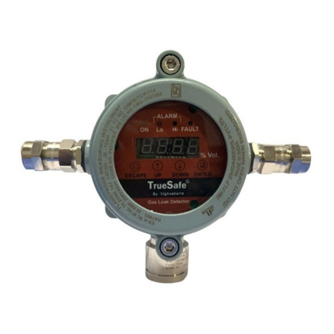
Vighnaharta TS21I-CLR-EX User manual

Vighnaharta Technologies Pvt. Ltd.
INSTRUCTION
INSTRUCTIONINSTRUCTION
INSTRUCTION
Industrial Grade Gas Leak Detector
Industrial Grade Gas Leak DetectorIndustrial Grade Gas Leak Detector
Industrial Grade Gas Leak Detector
(
((
(
LPG/PNG/CNG/LNG
LPG/PNG/CNG/LNGLPG/PNG/CNG/LNG
LPG/PNG/CNG/LNG
Warning:
Warning: Warning:
Warning:
Read & understand contents of this manual prior to operation. Failure to do so
could result in serious injury or death
Vighnaharta Technologies Pvt
Vighnaharta Technologies PvtVighnaharta Technologies Pvt
Vighnaharta Technologies Pvt
S.No.11/11 ,Karanjakar Estate,2
Phone no.: 91 20 32922630 / 32921306 Fax: 91 20 24339628.
Ema l: sales@v ghnaharta. n
Webs te: http://www.v ghnaharta. n
Industrial Grade Gas Leak Detector
INSTRUCTION
INSTRUCTIONINSTRUCTION
INSTRUCTION
MANUAL
MANUALMANUAL
MANUAL
Industrial Grade Gas Leak Detector
Industrial Grade Gas Leak DetectorIndustrial Grade Gas Leak Detector
Industrial Grade Gas Leak Detector
LPG/PNG/CNG/LNG
LPG/PNG/CNG/LNGLPG/PNG/CNG/LNG
LPG/PNG/CNG/LNG
)
))
)
(Revision 1.0
(Revision 1.0(Revision 1.0
(Revision 1.0)
))
)
Read & understand contents of this manual prior to operation. Failure to do so
could result in serious injury or death
.
Vighnaharta Technologies Pvt
Vighnaharta Technologies PvtVighnaharta Technologies Pvt
Vighnaharta Technologies Pvt
.
..
.
Ltd.
Ltd.Ltd.
Ltd.
S.No.11/11 ,Karanjakar Estate,2
nd
floor,Nanded Gaon,Pune-411041
Phone no.: 91 20 32922630 / 32921306 Fax: 91 20 24339628.
Industrial Grade Gas Leak Detector
– LPG
(Revision 1.0)
1
Read & understand contents of this manual prior to operation. Failure to do so

Industrial Grade Gas Leak Detector – LPG
(Revision 1.0)
2
Vighnaharta Technologies Pvt. Ltd.
Note
NoteNote
Note

Industrial Grade Gas Leak Detector – LPG
(Revision 1.0)
3
Vighnaharta Technologies Pvt. Ltd.
CONTENTS
CONTENTSCONTENTS
CONTENTS
1.Views of TS21I-CLR-EX.............................................................4
2. Introduction ...........………………………………………………….6
3.0 Instru ent Description…………….…………………………..…6
3.1 Application …………………………………………………………7
4.0 Instruction for wiring ………………………………………………7
4.1 Gas Leak Detector ………………………………………………..8
4.2 Connection ……………………………………………………….. 8
5. Specifications ……………………………………………………….9
6. LED la ps status …………...………………………………………9
7. Special feature....................................................................……10
8. Calibration procedure ………...…...………...…………….……….10
9. Do’s & don’t ……………………………………………………….…10
10.Typical wiring diagra …………..………………………………....11

Industrial Grade Gas Leak Detector – LPG
(Revision 1.0)
4
Vighnaharta Technologies Pvt. Ltd.
1.
1.1.
1.TS21I
TS21ITS21I
TS21I-
--
-CLR
CLRCLR
CLR-
--
-EX
EXEX
EX
Figure 1:Views of TS21I
Figure 1:Views of TS21IFigure 1:Views of TS21I
Figure 1:Views of TS21I-
--
-CLR
CLRCLR
CLR-
--
-EX
EXEX
EX

Industrial Grade Gas Leak Detector – LPG
(Revision 1.0)
5
Vighnaharta Technologies Pvt. Ltd.
Figure 2:Views of
Figure 2:Views of Figure 2:Views of
Figure 2:Views of TS21I
TS21ITS21I
TS21I-
--
-CLR
CLRCLR
CLR-
--
-EX
EXEX
EX

Industrial Grade Gas Leak Detector – LPG
(Revision 1.0)
6
Vighnaharta Technologies Pvt. Ltd.
2
22
2. I
. I. I
. Introduction
ntroductionntroduction
ntroduction
It is microcontroller based technology used for safety purpose in hazardous area
where chances of gas leakages. It is a well-accepted fact that in the industry or
large hotel kitchens using several LPG cylinders, the possibility of gas leak and
the severity of fire explosion hazard are very high. In spite of this very few
industries & hotels have installed the gas leak detectors.
The TS21I-CLR-EX is Flammable gas detector designed for permanent
installation; the unit is able to monitor the presence of combustible gases such as
LPG, CNG, and PNG etc. in a various locations like-
LPG CNG PNG gas storage areas.
LPG bullets and banks.
Plant locations.
Hotel, kitchens.
Industrial Canteens.
Gas filling stations.
3
33
3.0 Instrument
.0 Instrument.0 Instrument
.0 Instrument
Description
DescriptionDescription
Description
The TS21I-CLR-EX Gas leak detector consists of Aluminum enclosure that gives
flame protection. The electronic PCB assembly of the detector is housed in
junction box with sensor head connected to it.
Redled used for alarm indication at the time of gas leak detection and Yellow for
power on indication.
TS21I-CLR-EXgas leak detectors are connected to the gas alarm panel.When
gas leaks morethan 10% LEL occurs near any of the detector heads,
thecorresponding LED on the Gas Alarm Panel will glow indicating gas leakage

Industrial Grade Gas Leak Detector – LPG
(Revision 1.0)
7
Vighnaharta Technologies Pvt. Ltd.
at that location. Usually there is also a common hooter on Gas Alarm Panel,
which will give an audio alarm when gas leak occurs.
The alarm indication is provided by relay changeover. Detectors will operate the
relay at 10% LEL. (By default it is adjusted at 10% LEL).
3.1 Application
LPG CNG PNG gas storage areas.
LPG bullets and banks.
Plant locations.
Hotel, kitchens.
Industrial Canteens.
Gas filling stations.
4
44
4.
..
.0
0 0
0 Instruction or wiring
Instruction or wiringInstruction or wiring
Instruction or wiring
Important
Important Important
Important –
––
–
Connect only when the atmosphere is safe, i.e. when the
gas supply is stopped
Important
Important Important
Important –
––
–
Ensure electrical safety – do not work on live connections

Industrial Grade Gas Leak Detector – LPG
(Revision 1.0)
8
Vighnaharta Technologies Pvt. Ltd.
4
44
4.1
.1 .1
.1 Gas Leak
Gas Leak Gas Leak
Gas Leak Detector
DetectorDetector
Detector
•Remove the two screws on the detector head.
•Remove top cover.
•Connect 12VDC wire at J3.
•Connect the 3 wires at J4 (in case of relay based system)
•Put the cover and screws back.
•Connect earthing (GND) connection to the enclosure body of the transmitter.
4.2
4.2 4.2
4.2 Connection
ConnectionConnection
Connection
One or more detector heads can be connected to one zone of an alarm panel.
The PCB inside the detector has a terminal with five connections. The top section
of the terminal can be unplugged from the PCB from easier access to the
securing screws. The top section is non-reversible and should be firmly pushed
onto the PCB wiring.
The
The The
The fi e connections are
fi e connections are fi e connections are
fi e connections are -
--
-
+
++
+
-
--
-
NO
NONO
NO
P
PP
P
NC
NCNC
NC
1.
1. 1.
1. “
““
“+
++
+”
””
”:
: :
: 12VDC positive (Power supply positive)
2.
2. 2.
2. “
““
“–
––
–“
““
“:
: :
: 0V DC ground (Power supply positive)
3.
3.3.
3.“
““
“P
PP
P”
””
”:
::
: Common pole of the potential free relay Contact.
4.
4. 4.
4. “
““
“NO
NONO
NO”
””
”:
::
: Normally Open pole of the potential free relay Contact.
5.
5. 5.
5. “
““
“NC
NCNC
NC”
””
”:
::
: Normally Close pole of the potential free relay Contact.

Vighnaharta Technologies Pvt. Ltd.
5
55
5.
. .
. S
SS
Specifications
pecificationspecifications
pecifications
1.
1.1.
1.
Model
ModelModel
Model: TS21I
: TS21I: TS21I
: TS21I-
--
-CLR
CLRCLR
CLR-
--
-Ex
ExEx
Ex
2.
2.2.
2.
Power
PowerPower
Power
supply
supplysupply
supply
Input
InputInput
Input:
::
:
12VDC±0.5
3.
3.3.
3.
Displ y
Displ yDispl y
Displ y
Indic tion
Indic tionIndic tion
Indic tion:
::
:
Power
Gas
Leak
4.
4.4.
4.
Rel y
Rel yRel y
Rel y
output:
output:output:
output:
Potential free SPDT relay contact provision
5.
5.5.
5.
Response
ResponseResponse
Response
Time:
Time:Time:
Time:
Less t an 10 sec.
6.
6.6.
6.
Al rm
Al rmAl rm
Al rm
Mode:
Mode:Mode:
Mode: latc ed
7.
7.7.
7.
Power
PowerPower
Power
Consumption:
Consumption:Consumption:
Consumption:
250mA (300mA w en relay is activated)
8.
8.8.
8.Housing
HousingHousing
Housing:
::
:Aluminum
Housing
6
66
6. LED
. LED. LED
. LED
lamps status
lamps statuslamps status
lamps status
Two LED lamps on t e PCB indicate t e various
used to
diagnose t e different c
And Power
(Yellow) may be located at various locations depending on t e type of
PCB inside t e enclosure.
LED l mps sequence on PCB
LED l mps sequence on PCBLED l mps sequence on PCB
LED l mps sequence on PCB
Industrial Grade Gas Leak Detector
12VDC±0.5
Power
ON:-Yellow color led
Leak
: -Red color led
Potential free SPDT relay contact provision
.
Less t an 10 sec.
250mA (300mA w en relay is activated)
Housing
Two LED lamps on t e PCB indicate t e various
modes. T ese
lamps can be
diagnose t e different c
onditions. T e two LED lamps Gas Leak
(Yellow) may be located at various locations depending on t e type of
LED l mps sequence on PCB
LED l mps sequence on PCBLED l mps sequence on PCB
LED l mps sequence on PCB
Industrial Grade Gas Leak Detector
– LPG
(Revision 1.0)
9
lamps can be
onditions. T e two LED lamps Gas Leak
(Red)
(Yellow) may be located at various locations depending on t e type of

Industrial Grade Gas Leak Detector – LPG
(Revision 1.0)
10
Vighnaharta Technologies Pvt. Ltd.
7
77
7.
..
.S
SS
Special eature
pecial eaturepecial eature
pecial eature
•Continuous monitoring for gas leaks by gas detector placedat different
locations in the hazardous area.
•Microprocessor based design.
•When gas level crosses 10% of LEL the detector switches relay output.
•Alarm status-latching provision on local alarm indicator
.
8
88
8.
. .
. C
CC
Calibration procedure
alibration procedurealibration procedure
alibration procedure
•Put the jumper at JP1 if it is OFF.
•Power on the detector.
•Then detector is in calibration mode.
•Expose the system to the calibration gas (10% LEL).
•System shall automatically calibrate after 2min.
•After that that removes the jumper.
9
99
9. Do’s
. Do’s. Do’s
. Do’s&
&&
&
D
DD
Don’t
on’ton’t
on’t
•Don’t expose the sensor to gas concentration higher than itsprescribed range.
Go to the next page to viewing typical wiring diagram
Go to the next page to viewing typical wiring diagramGo to the next page to viewing typical wiring diagram
Go to the next page to viewing typical wiring diagram

Industrial Grade Gas Leak Detector – LPG
(Revision 1.0)
11
Vighnaharta Technologies Pvt. Ltd.
10
1010
10.Typical wiring diagram
.Typical wiring diagram.Typical wiring diagram
.Typical wiring diagram
Figure
Figure Figure
Figure 3
33
3:
::
:Typical wiring diagram
Typical wiring diagramTypical wiring diagram
Typical wiring diagram

Industrial Grade Gas Leak Detector – LPG
(Revision 1.0)
12
Vighnaharta Technologies Pvt. Ltd.
Routine Check for TrueSafe
Routine Check for TrueSafe Routine Check for TrueSafe
Routine Check for TrueSafe TS21 I
TS21 ITS21 I
TS21 I-
--
-CLR
CLRCLR
CLR-
--
-EX
EXEX
EX
To ensure that Truesafe TS21 I-CLR-Ex is in working condition,it is necessary to check
working of Gas LE by manual testing.
For checking units sensing capability,it is necessary to check the unit once in a month.
Note:If the detector is stored for long time without power,it needs to be powered ON for
stability as per following table
Storage Time without Electricity Suggested Preheat Time
Less than 1 month Not less than 48 hours
1 month to 6 month Not less than 72 hours
More than 6 month Not less than 168 hours

Industrial Grade Gas Leak Detector – LPG
(Revision 1.0)
13
Vighnaharta Technologies Pvt. Ltd.
Table of contents
Other Vighnaharta Gas Detector manuals

Vighnaharta
Vighnaharta TrueSafe TS12CLR User manual

Vighnaharta
Vighnaharta AGDS -32 User manual
Vighnaharta
Vighnaharta TS21 I IR CO2 User manual

Vighnaharta
Vighnaharta TrueSafe TS21I ELE O2 User manual

Vighnaharta
Vighnaharta TrueSafe Gas Cloud User manual

Vighnaharta
Vighnaharta TrueSafe TS 21 I-HC User manual

Vighnaharta
Vighnaharta TrueSense CO-DETECTOR User manual
Popular Gas Detector manuals by other brands

Halma
Halma Crowcon Xgard Installation, operating and maintenance instructions

Teledyne
Teledyne Gasurveyor 700 user manual

Thorne & Derrick
Thorne & Derrick SafEye Quasar 900 User and maintenance manual

GDS
GDS 404 Series Operating handbook

LI-COR
LI-COR LI-7815 instruction manual

Emerson
Emerson Rosemount 936 quick start guide