manuals.online logo
Brands
  1. Home
  2. •
  3. Brands
  4. •
  5. Seitron
  6. •
  7. Gas Detector
  8. •
  9. Seitron BEAGLE plus L User manual

Seitron BEAGLE plus L User manual

This manual suits for next models

2

Other Seitron Gas Detector manuals

Seitron RGI 000 MBX2 User manual

Seitron

Seitron RGI 000 MBX2 User manual

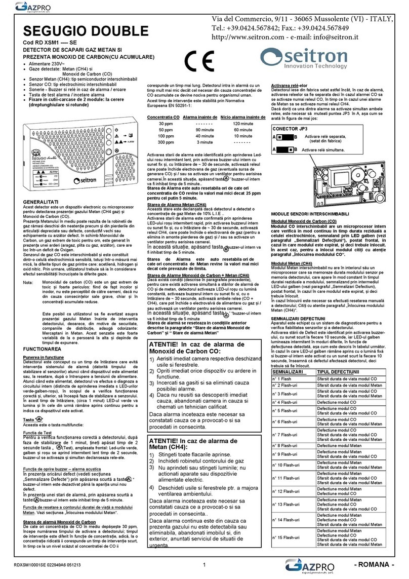
Seitron SEGUGIO DOUBLE RD XSM1 SE Series User manual

Seitron

Seitron SEGUGIO DOUBLE RD XSM1 SE Series User manual

Seitron RGY S00 MBP4 Instruction Manual

Seitron

Seitron RGY S00 MBP4 Instruction Manual

Seitron BEAGLE User manual

Seitron

Seitron BEAGLE User manual

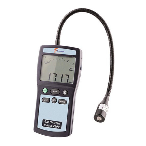
Seitron 7899 User manual

Seitron

Seitron 7899 User manual

Seitron RGD COH MP1 1SE User manual

Seitron

Seitron RGD COH MP1 1SE User manual

Seitron POLF02 User manual

Seitron

Seitron POLF02 User manual

Seitron RYM02M Series Operator's manual

Seitron

Seitron RYM02M Series Operator's manual

Seitron SEGUGIO WIRELESS Series User manual

Seitron

Seitron SEGUGIO WIRELESS Series User manual

Seitron BEAGLE plus User manual

Seitron

Seitron BEAGLE plus User manual

Seitron SGI 1 M Series User manual

Seitron

Seitron SGI 1 M Series User manual

Seitron RI-01RM User manual

Seitron

Seitron RI-01RM User manual

Seitron BEAGLE User manual

Seitron

Seitron BEAGLE User manual

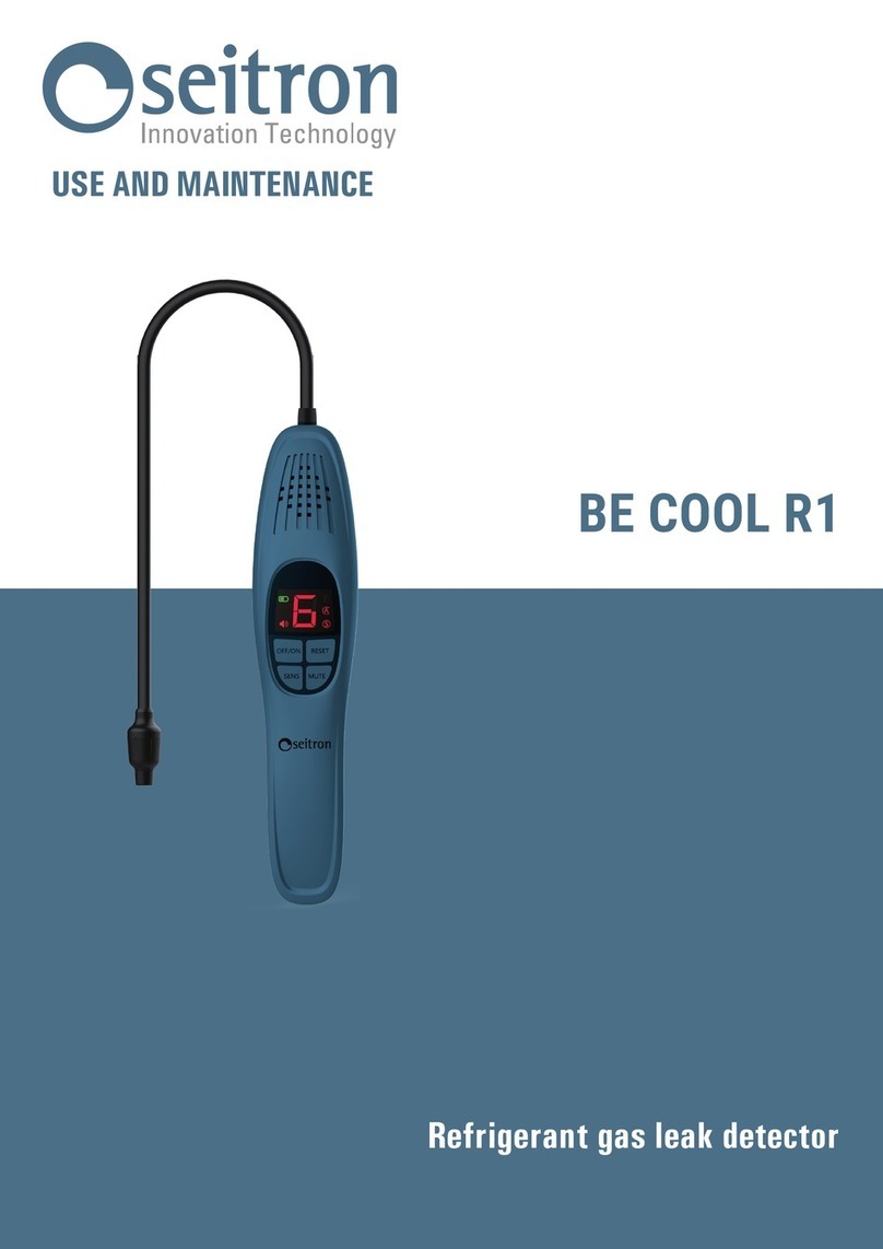
Seitron BE COOL R1 User guide

Seitron

Seitron BE COOL R1 User guide

Seitron BEAGLE L User manual

Seitron

Seitron BEAGLE L User manual

Seitron RGY 000 MBP4 Instruction Manual

Seitron

Seitron RGY 000 MBP4 Instruction Manual

Seitron BE COOL R1 User manual

Seitron

Seitron BE COOL R1 User manual

Popular Gas Detector manuals by other brands

Macurco GD-6 Operation manual

Macurco

Macurco GD-6 Operation manual

Evikon E2632 user manual

Evikon

Evikon E2632 user manual

Perry 1GA 50917MET/P Installation and operating instructions

Perry

Perry 1GA 50917MET/P Installation and operating instructions

MSA altair 5 operating manual

MSA

MSA altair 5 operating manual

DOD Technologies ChemLogic CL96 operating manual

DOD Technologies

DOD Technologies ChemLogic CL96 operating manual

DEGA NS III LCD Series instruction manual

DEGA

DEGA NS III LCD Series instruction manual

RKI Instruments 35-3001A-08-01 Operator's manual

RKI Instruments

RKI Instruments 35-3001A-08-01 Operator's manual

isweek AS8900 manual

isweek

isweek AS8900 manual

Beacon MEGA Installation, operation and maintenance instructions

Beacon

Beacon MEGA Installation, operation and maintenance instructions

MSA ULTIMA X5000 operating manual

MSA

MSA ULTIMA X5000 operating manual

Critical Environment Technologies CGAS-A Series Installation & operation manual

Critical Environment Technologies

Critical Environment Technologies CGAS-A Series Installation & operation manual

Sensidyne SensAlert Plus instruction sheet

Sensidyne

Sensidyne SensAlert Plus instruction sheet

Gas Sense GS-300.A Operation manual

Gas Sense

Gas Sense GS-300.A Operation manual

Evikon PluraSens E2638 Series user manual

Evikon

Evikon PluraSens E2638 Series user manual

Bosean Electronic Technology BH-4M user manual

Bosean Electronic Technology

Bosean Electronic Technology BH-4M user manual

Coster RGS 328 instructions

Coster

Coster RGS 328 instructions

Sygonix 2483186 operating instructions

Sygonix

Sygonix 2483186 operating instructions

Compur Monitors Tracer manual

Compur Monitors

Compur Monitors Tracer manual

manuals.online logo
manuals.online logoBrands
  • About & Mission
  • Contact us
  • Privacy Policy
  • Terms and Conditions

Copyright 2025 Manuals.Online. All Rights Reserved.

The sensor module can be replaced only twice and the
replacement must be done by qualified personnel only.
SENSOR REPLACEMENT
Every five years (max twice) the internal sensor module
must be replaced with a new precalibrated sensor module.
The replacement must be done by qualified personnel
according to the following instructions:
1. Use the relevant sensor module part:
BEAGLE plus L: AC MG01
BEAGLE plus M: AC MM01
2. Remove the power supply from the detector.
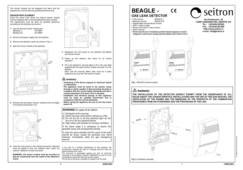
3. Remove the detector’s panel as shown in Fig. 2.
4. Spot the sensor module to be replaced:
5. Remove the old sensor module, holding firmly the edges
of the board and pulling it out:
6. Insert the new sensor in the relevant connector. Attention
must be payed in that the module’s pins match the
relevant detector’s female connector.
WARNING: the sensor module must be mounted so
that its components face the inside of the detector’s
board.
RGD GP5 MP1 RSE 020408D4 270212
7. Reposition the front panel on the detector and tighten
the relevant screw.
8. Power up the detector and check for its correct
operation.
9. Fill in the detector’s warning label or fill in the new label
supplied with the spare sensor module and stick it on the
detector.
Note: that the warning label’s date must be 5 years
ahead the set up of the new sensor module.
a
aa
a
WARNING
- Tampering of the device exposes to electrical hazard
or malfunction.
- The appliance must be wired to the electric mains
through a switch capable of disconnecting all poles in
compliant with the current safety standards and with a
contact separation of at least 3 mm in all poles.
- Installation and electrical wirings of this appliance
must be made by qualified technicians and in
compliance with the current standards.
- Before wiring the appliance be sure to turn the mains
power off.
* NOTE:
- System configuration which contemplates the
detector and a remote sensor is not covered by the
conformity to IMQ marking.
In the view of a constant development of their products, the
manufacturer reserves the right for changing technical data and
features without prior notice.
The consumer is guaranteed against any lack of conformity
according to the European Directive 1999/44/EC as well as to the
manufacturer’s document about the warranty policy.
The full text of warranty is available on request from the seller.
WARNING! In case of an alarm:
1) Extinguish all fire sources.
2) Close main gas valve (either methane or LPG).
3) Do not turn on or off any electrical light; do not
turn on or off any electrical device.
4) Open doors and windows to increase ventilation.
If the alarm stops it is necessary to search the
possible cause and consequently provide.
In case the alarm persists and the cause of the leak
cannot be found, vacate the premises and, from
external, immediately notify the gas emergency
service.
4 - ENGLISH -
60mm
BEAGLE plus
plusplus
plus
GAS LEAK DETECTOR
•
LPG version: BEAGLE plus L
•
Methane version: BEAGLE plus M
•
Replaceable semiconductor sensor
•
230V~ power supply
•
Buzzer and relay in case of alarm
•
Alarm test key
•
Flush mount over 2 modules junction boxes (square or round shaped)
RGD GP5 MP1 RSE 020408A4 270212
1
Fig. 2: Installation example of BEAGLE plus -.
a
WARNING
THE INSTALLATION OF THE DETECTOR DOESN'T EXEMPT FROM THE OBSERVANCE OF ALL
RULES ABOUT THE CHARACTERISTICS, INSTALLATIONS AND THE USE OF THE GAS DEVICES, THE
VENTILATION OF THE ROOMS AND THE EMISSIONS OF THE PRODUCTS OF THE COMBUSTION
PRESCRIBED FROM UNI STANDARDS AND THE PROVISIONS OF THE LAW.
- ENGLISH -
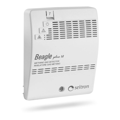
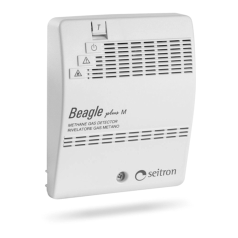
Fig. 1:BEAGLE plus - external aspect.
Beagle
T
LPG GAS DETECTOR
RIVELATORE GAS GPL
plus
L
Beagle
T
METHANE GAS DETECTOR
RIVELATORE GAS METANO
plus
M
Via Prosdocimo, 30
I-36061 BASSANO DEL GRAPPA (VI)
Tel.: +39.0424.567842
Fax.: +39.0424.567849
http://www.seitron.it
e-mail: info@seitron.it
RGD GP5 MP1 RSE 020408B4 270212
2
Fig. 5:Wiring diagram for several Beagle plus and one manual reset Normally Closed 230V~ electro-valve.
Fig. 3: Wiring diagram with one Beagle plus and one
manual reset Normally Closed 230V~ electro-valve. Fig. 4: Wiring diagram with one Beagle plus and one man-
ual reset Normally Open 230V~ electro-valve.
Fig. 6:Wiring diagram for several Beagle plus and one manual reset Normally Open 230V~ electro-valve.
WIRING DIAGRAM
- ENGLISH -
NL 3 4 5
230V~ N.C.
E.V.
230V~
L N
NL 345
N
230V~
L
E.V.
230V~ N.O.
3
230V~
L N
L N 3 4 5L N 4 5
230V~ N.O.
230V~
L N
E.V.
4
NL
230V~
L N 35
230V~
L N
L N 345
E.V.
230V~ N.C.
TECHNICAL FEATURES
Power supply: 230V~ -15% +10% 50/60Hz
Power absorption: 2VA
Sensor type: SnO
2
semiconductor
replaceable
Detected gas: BEAGLE plus L: LPG
BEAGLE plus M: Methane
Alarm threshold: 10% L.E.L.
Contacts rating: 5A @ 250V~ SPDT
Indicators: Active: Green led on
Fail: Yellow led on
Alarm: Red led on
Alarm: Buzzer
Heating delay at turn-on: ~ 30 seconds
Relay activation delay: ~ 5 seconds
Sensor lifetime: 5 years
Operating temperature: 0°C .. 40°C
Storage temperature: -10°C .. +50°C
Humidity limits: 20% .. 80% RH
(non condensing)
Protection rating: IP 42
Case: Material: ABS + PC
Color: Signal white (RAL 9003)
Size: 85 x 107 x 38 mm
(W x H x D)
Weight: ~ 260 gr.
Product Reference Standard: EN 50194-1 (2009)
EMC Reference Standard: EN 50270 (2006)
LVD Reference Standard: EN 60335-1 (2002)
OPERATION
This BEAGLE plus (Fig. 1) is a flammable gas leakage
domestic detector. When exposed to a gas concentration
much lower than the danger level, the detector turns on a
red light and a buzzer, then, after 5 seconds it, turns on a
relay which can be used to stop the gas supply.
Note: The user might smell the presence of gas before the
detector does; this happens because the distribution
companies use to add odorizers to natural gas and LPG.
This sensation is extremely variable from person to person,
and depends on the exposure time.
To test the correct operation of the detector, press the T
(Test) button on the frontal panel: the green, yellow and
red LEDs will turn on; the buzzer will buzz and after 5
seconds the relay contact is activated.
The BEAGLE plus is equipped with a delay line which
avoids the intervention of the alarm system (in order for the
gas sensor to heat up) whenever the device is turned on or
even after a mains black-out, as soon as the power comes
back. After that delay (about 30 seconds) the yellow LED
turns off and the green LED remains on to show that the
detector is powered.
The BEAGLE plus features an auto-diagnostics system
which verifies the sensor reliability.
When the yellow indicator is turned on (sensor fail) the
possible causes must be searched among the following:
- sensor fail;
- sensor disconnected;
- detector malfunctioning.
INSTALLATION
This device is intended for wall mount only, with relevant
electrical wiring made through the fixed wiring, not exposed
to people and connected to the fixed electrical wiring. The
device safety and operational features are only granted
when the electrical wiring is made through the proper
opening for cables located in the plastic plate.
To access to the internal terminals, remove the front panel
by loosening the screw (Fig. 2).
Make the electrical wiring following the suggested wiring
diagrams in Fig. 3, 4, 5 or 6.
Please note that the intervention delay is strictly dependant
both on a correct positioning of the detector in the room and
to the type of gas to be detected.
In case of 'heavy' gases (as for LPG) an installation in low
places is advisable (about 30 cm from floor level), meanwhile
for ’light’ gases like methane in high places (about 30 cm
from ceiling level).
Please avoid to install this gas detector in any position in
which its operational features could be compromised, such
as the following:
- in an enclosed space (e.g. in a cupboard or behind a
curtain;
- directly above a sink;
- next to a door or window;
- next to an extractor fan;
- in an area where the temperature may drop below - 10°C
or exceed + 40°C;
- where dirt and dust may block the sensor;
- in a damp or humid location.
Do not use the following substances in the device
immediate adjacency:
- alcohol, fuels
- solvents and diluents
- adhesives, silicones products and colours
- cleaning detergents
- perfumes
- spray products in general
Clean the device only using a cloth damped with water.
In order to grant a real safety, a gas detector must be
coupled to an electro-valve capable of blocking the gas flow
in the event of an alarm.
Both the gas unit and the solenoid valve must comply with
the law prescriptions in force in the country concerned.
BEAGLE plus detector can be connected to two types of
electro-valve:
- 230V~ Normally Open electro-valve;
- 230V~ Normally Closed electro-valve;
In order to check the proper efficiency of the device sensor
a specific test gas bottle (optional) is made available which
must be used according to the enclosed instructions.
WARNING: Any other method for testing, such as the
use of cigarette lighters, flammable vapours etc., can
lead to wrong conclusions as well as to the irreversibile
damage of the sensor itself.
WARNING
The installer is reminded to fill in and apply the sticking label
supplied with the product by writing the installation date of
the product, the date before which the sensor module must
be replaced, the date before which the sensor module must
be replaced the second and last time and finally the date
before which the entire detector must be replaced.
The latter is stated on 15 solar years from the installation
date of the product.
This label must be applied, at installer care, on a visible side
of the gas detector once it has been fixed in its typical
installation position.
Warning label:
RGD GP5 MP1 RSE 020408C4 270212
3 - ENGLISH -