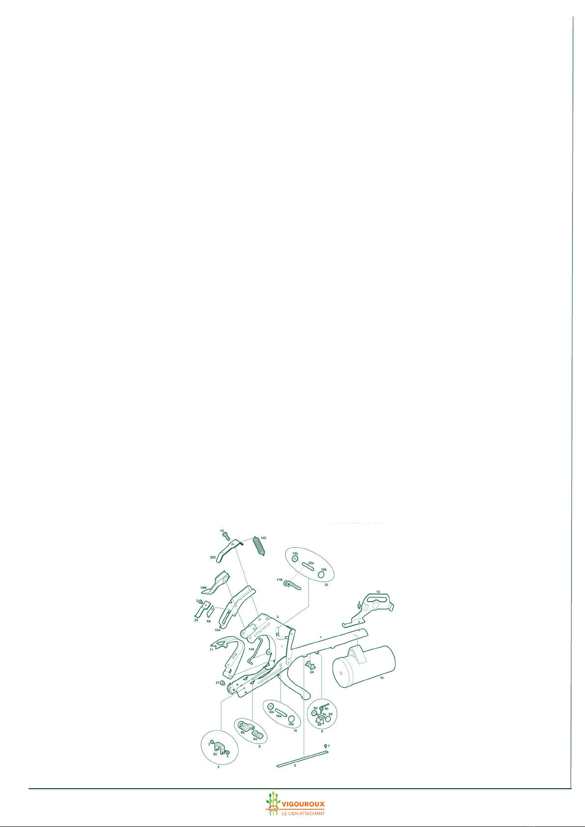
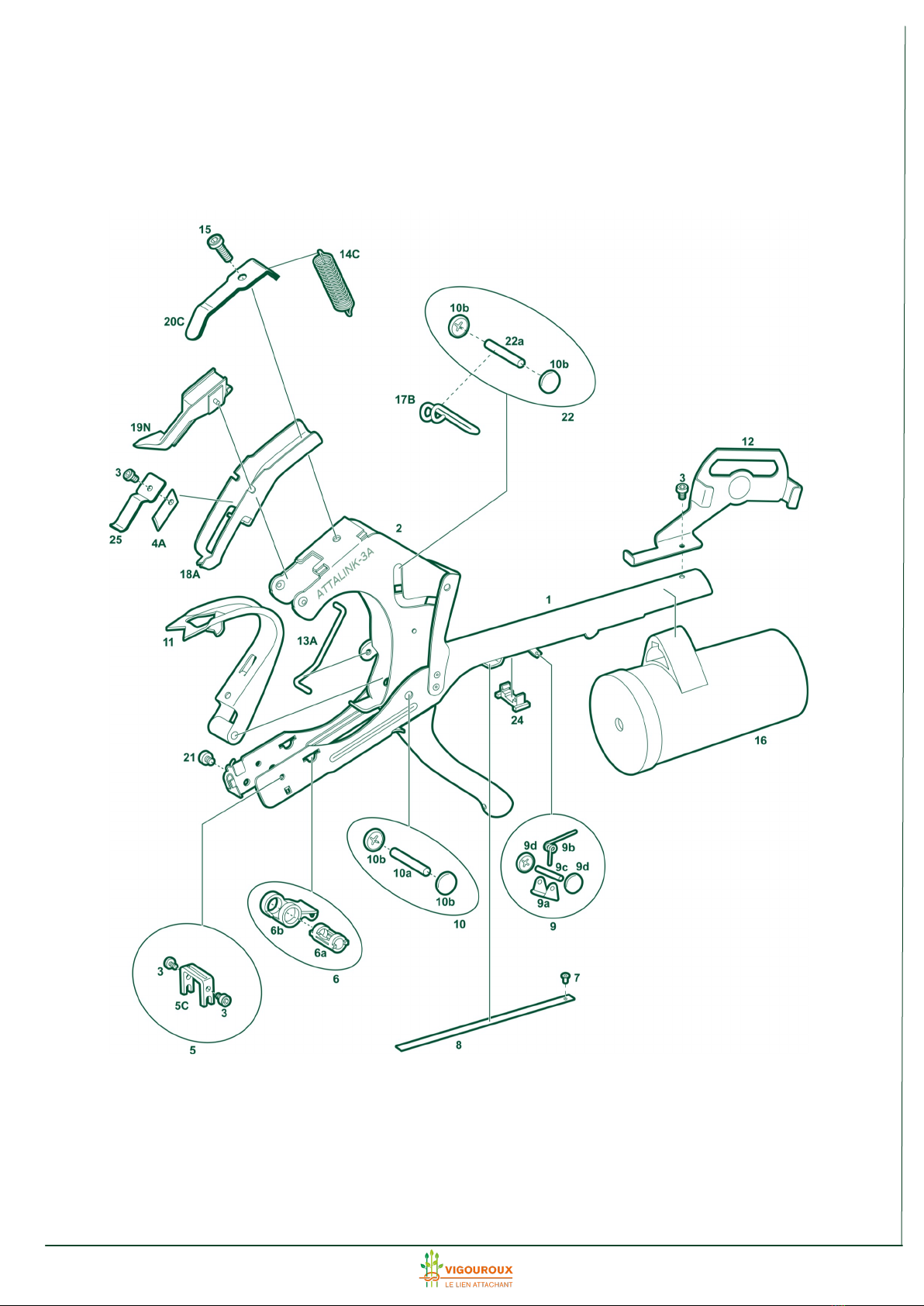
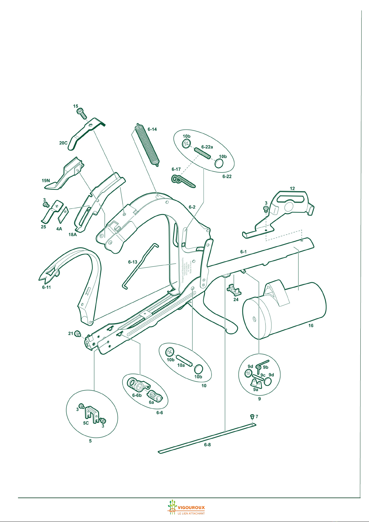
VIGOUROUX Attalink-3A Owner's manual

ATTALINK
PARTS, FEATURES
AND ADJUSMENTS

2
CONTENTS
EXPLODED VIEW OF THE ATTALINK
HAND HELD TYING TOOL PAGE 3
DETAILED VIEW OF PARTS PAGE 5
TOOL INSPECTION PROCEDURE PAGE 10
ADJUSTMENT AND PART CHANGING PAGE 11

3
EXPLODED VIEW OF THE ATTALINK HAND HELD TYING TOOL
(View of ATTALINK-3A )

4
EXPLODED VIEW OF THE ATTALINK HAND HELD TYING TOOL
(View of ATTALINK -6A)

5
Part n°20C –Strip spring holding the thread blocking device (part n°19N)
This part allows the thread blocking device to actuate when the
ATTALINK tying tool opens and repositions it opposite the thread feed
eye (in part n°1).
The shape of the strip spring, which pushes against the thread blocking de-
vice (part n°19N) is important: it stabilises the thread blocking device and
gives it enough freedom to move upwards and downwards to perform its
function.
The tension of this spring has an effect on overall performance of the tool:
- not enough tension: the thread blocking device (part n°19N) may trigger
due to the tension of the thread when the object to be tied is introduced. If
this happens, it snags against the thread feed eye or passes underneath the
eye and fails to release the cut thread,
- too much tension: the thread blocking causes too much friction, thereby
preventing the tying tool from opening again.
Please refer to the adjustment and part changing manual, paragraph VII, § 4
(photo 28).
Part n°19N –Complete thread blocking device
This part consists of a metal and a plastic part hinged to a pin and held in
position by a spring.
The thread blocking device catches the thread and keeps it blocked for the
time it takes to apply the tie, and then releases it.
The shape of the metal part gripping the thread is crucial for smooth opera-
tion of the entire system:
- it grips the thread as it leaves the feed eye
- it effectively blocks the thread
Refer to the adjustment manual, paragraph VII.
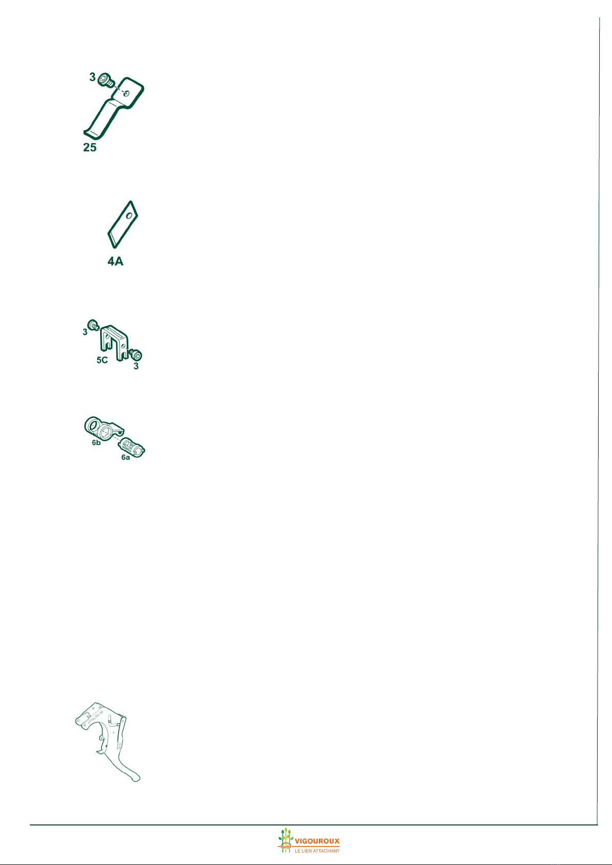
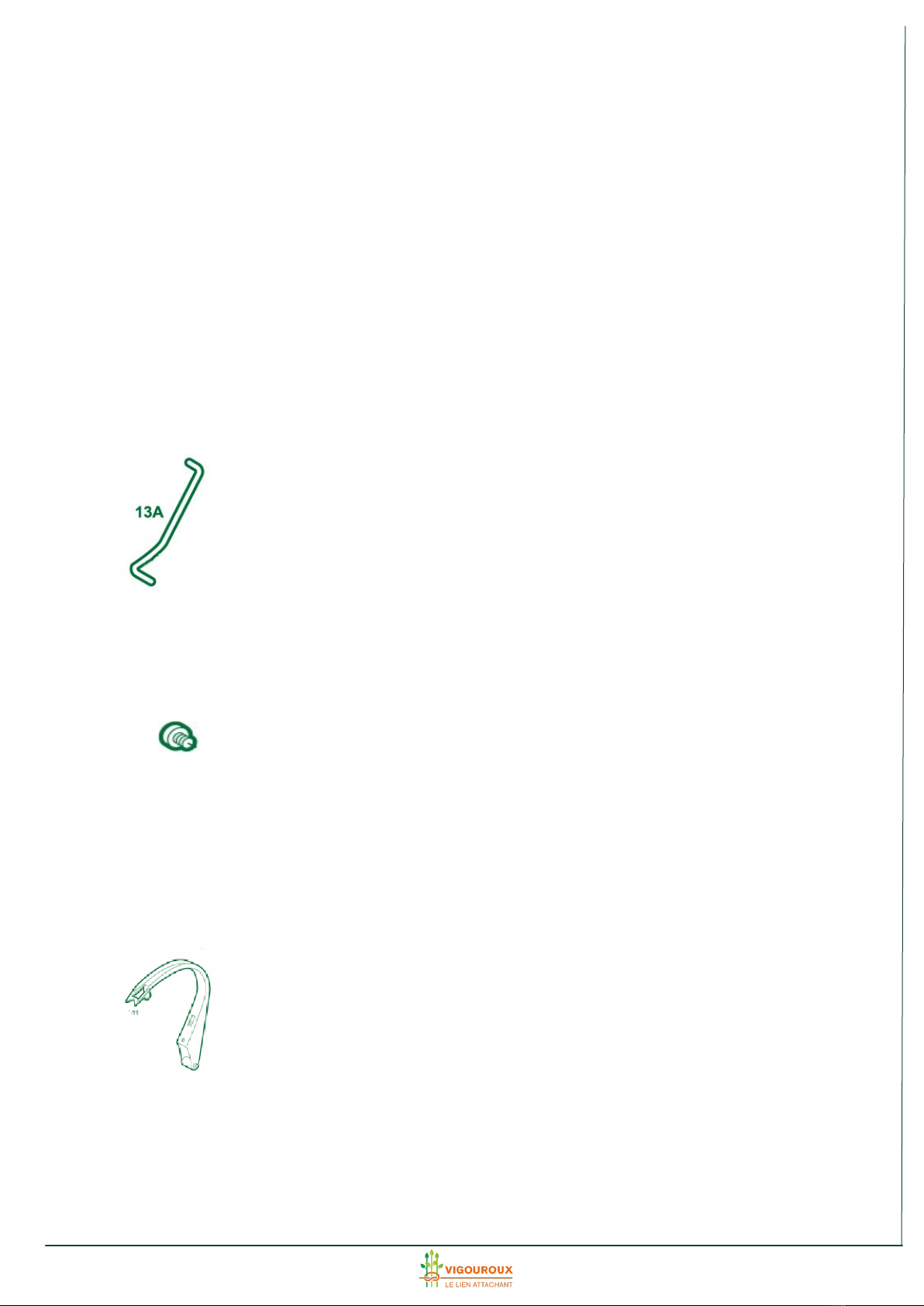
Part n°18A –Thread blade support casing
- Aligns the thread blade (part n°4A) with the thread cutter (part nº 5C) so
that the blade travels through the slits in the thread cutter.
- Acts as an end-of-travel stop for the hand tool: the two tabs on either side
of the blade provide an end-of-travel stop for the handle when closing.
Adjustment:
Following an impact, it may be necessary to realign the blade (part n°4) and
the cutting device (part n°5). To do this, use leverage on part n°18A to bend
it back in the right direction.
DETAILED VIEW OF PARTS

6
Part n°25 –Thread retainer
This part is used to hold the free end of the thread before it is cut. Without
it, the end is not always snipped off properly and the tie looks uneven.
Adjustment:
Bend the end so that it makes light contact with the top of the thread cutter
(part nº 5C)
Part n°4A –Tempered steel thread blade.
Replacement: refer to paragraph VI of the adjustment manual.
Part n°5 –Cutting device
If required, the cutting device may be slightly adjusted to the thread blade,
by unscrewing the two screws and repositioning the slit.
Part n°6 –Metal cutter (part n°6 for ATTALINK-3A and part n°6-6 for
ATTALINK-6A)
The metal cutter consists of two parts: an inner cylinder and an outer shear-
ing device. The rotation of the outer part cuts the wire and shapes the
crimping ring around the thread.
The ring is correctly formed when the metal protrudes approximately 1 mm
above the slit in the inner cylinder.
The height of ring can be adjusted as explained in the adjustment manual,
paragraph V (photo 14).
If the metal reel advances upwards too far, the ring does not encircle the
two ends of the thread completely and the tie does not hold.
If the reel does not advance far enough upwards, the ring is not strong
enough to hold the two ends of the thread and the tie does not hold.
When this part is worn, the cut is uneven and the ties do not hold.
To keep this part working smoothly for a long time, it must be oiled regularly
but sparingly, as described in the instructions for use.
Part n°2 –Handle (part n°2 for ATTALINK-3A and part n°6-2 for
ATTALINK-6A)
This is the moving part that actuates all the tying mechanisms:
- griping the thread

7
- bringing the two ends of the thread together
- cutting the thread
- shaping and cutting the aluminium ring
- feeding the metal reel
The metal reel feed mechanism is connected to this part:
- when closed, the handle presses the metal reel into a curve, pulling out
just enough length to form the ring.
- when opened, the metal reel is fed upwards into the cutting device as the
curve straightens out.
Adjusting ring height: explained in the adjustment manual paragraph V
(photo 14).
Part n°13 –Metal cutter rod (part n°13A for ATTALINK-3A and part n°6-
13A for ATTALINK-6A)
This part transfers movement from the handle to the metal cutter so that
the ring is formed when the threads are properly positioned for crimping.
Firstly, an optimum cutting area is defined, shown by A on photo 15 in the
adjustment manual. The active length of the part is then adjusted by curving
it using the tool shown in photo 16.
Part n°21 - Nylon thread tension screw
Tighten or loosen this screw to regulate the tension produced when tying.
Note that to prevent the thread from escaping from its feed eye when work-
ing, it must feed under the rod compressed by this screw (see instructions
for use).
Part n°11 –Thread advancer (part n°11 for ATTALINK-3A and part n°6-11
for ATTALINK-6A)
This part brings the 2 threads against the aluminium reel and holds them in
place while the ring is formed. It is actuated when the handle closes via the
pin attached to the frame (part n°1).
21

8
Adjusting the shape of the 2 thread advancers:
- The upper part must clear the top of the metal cutter (part n°6b) by ap-
proximately 2 mm when the tool is closed.
- The lower part must reach halfway up the metal cutter (part n°6a) and
must stop 1 mm before coming into contact with the aluminium crimping
reel. If this distance is greater, it can be adjusted by modifying the curve of
the guard (on part n°1): tap near the hinge point around the pin.
Part n°17 –Tie advancer control pin (part n°17B for ATTALINK-3A and n°
6-17 for ATTALINK-6A)
To replace this item, refer to the adjustment manual, paragraph VIII.
Parts n°7 and n°8 - Rivet and metal strip guide (part n°7 and 8 for
ATTALINK-3A and part n°7 and 6-8 for ATTALINK-6A).
These parts guide and align the metal reel to provide regular ring height.
To change them, refer to paragraph III of the adjustment manual.
Part n°9 –Aluminium reel brake assembly
This assembly is mounted on the stationary part (part n°1) of the tool. It
consists of a sharpened brake device, an axle, a spring and 2 retaining clips
holding the axle. It regulates the metal reel feed.
For sharpening and changing, see the adjustment manual, paragraphs I and
II
Part n°24 –Aluminium reel brake shim
Disables the action of the brake while the metal reel is being changed.
See the ATTALINK instruction manual
Part n°16 –Thread dispenser
See the ATTALINK instruction manual
24

9
Part n°12 –Aluminium reel spool bracket
Holds the metal reel spool. When the spool is fitted to its bracket, the reel
feed slit in the plastic box must be located exactly opposite the thread dis-
penser.
See the ATTALINK instruction manual (drawing n°14)
Part n°1 –Large arm (part n°1 for ATTALINK-3A and part n°6-1 for
ATTALINK-6A)
Its upper end positions the thread feed so that it can be gripped by the
thread blocking device (part n° 19N).
The angle of the upper end must match the description for photo 18 in
paragraph VII of the adjustment manual.
The curve of the guard has an effect on the travel of the thread advancer
(part n°11). In cases of extreme wear, the play on the thread advancer can
be taken up when the tool is in closed position by nudging back the guard
towards the thread advancer.
Part n°10 –Main axle and retaining clips
To remove and refit the axle, use the same procedure as applies to part
n°22.
Part n°22 –Play on the sliding axle
Extensive wear may limit the travel of the thread advancer. This part should
then be changed. Refer to paragraph VIII of the adjustment manual.

10
TOOL INSPECTION PROCEDURE

11
5
4 6
NB : the illustrations below correspond to ATTALINK model 6A and may differ slightly
from other models
I- Sharpening the metal brake if the metal strip does not feed through
correctly
Sharpen the brake flat on the lower side (photo 1) and bevelled on the upper side (photo
2), with a medium grain file, taking care to remove metal filings as they appear on the blade
of the brake. To do this, start by sharpening the flat underside, and then gently work your
way to the upper side of the blade. To check how sharp the blade is, pull the metal strip
back firmly with a pair of pliers: the brake should stop the metal strip from moving back
(photo 3).
II- Changing the metal brake or the metal brake spring.
1- Lift the brake support using a screw driver (photo 4).
IMPORTANT!!! take careful note of the position of the support in relation to the arm of the
pincer in order to be able to return it to its original position later photo 4bis).
2- Remove the 2 hub caps on the sides of the brake axis.
3- Remove the brake axis taking care with the spring which can jump out (protect your
face), and remove the brake and the spring (photo 5).
1 2 3
4 bis
ADJUSTMENT AND PART CHANGING

12
4- Change the part which needs replacing.
5- Replace the axis together with the spring and the brake, as well as the new hub caps ;
one removed, a cap is difficul to return to its initial position.
6- Push the brake support back to its initial position.
7- If the spring has been replaced, trim the short end level with the brake to avoid risk of
injury when using the pincers. Also tension the end of the spring resting on the inner side of
the arm to ensure the brake is fairly stiff (photo 6): if the spring is too slack, the brake blade
will not work properly.
III- Changing the spring-blade.
1- Remove the rivet using a knife (photo 7) and remove the worn blade.
2- Slide the new blade (part n°8 / n°6-8) into the slit of the metal cutter maintaining the
curvature (inset photo 8).
3- Insert the blade with tis new rivet into the hole in the blade support passing the rivet
from above the hole.
4- Flatten the head of the rivet using multiple pliers taking care not to modify the position
of the brake support system (photo 9).
IV- Complete or partial replacement of the metal cutter.
8 9
7
11 12
10

13
1- Remove the aluminium strip from the slit in the metal cutter.
2- Remove the fixing screw from the guillotine (n°5C) which is located on the nylon screw
side (photo10).
3- Open out one side of the arm so that the metal cutter is levered out of its normal posi-
tion photo 11).
4- Replace the part(s) needing replacement and return the guide thread blade to the slit in
the metal cutter.
5- Place the tenons of the internal part of the metal cutter (part n°6a) opposite their sock-
ets and insert firmly using a pair of multiple pliers (photo 12).
6- Screw the blocking screw back onto the guillotine (part n°5C).
7- Adjust the settings for metal cutting (see paragraph V).
V- Adjusting the metal cutting
Vigouroux provides a tool which can be used specifically for this (photo 16)
Check that the metal strip is feeding correctly and that the cut is occurring at the correct
moment of the closing cycle.
1- The metal should extend approx. 1 mm beyond the inner part (photo 13).
If the metal does not feed through sufficiently, slightly fold the adjusting lip on the handle
by pushing it forward ; if it is feeding through too fast, fold the lip backwards (photo 14).
The lip allows one to increase or decrease the curvature of the metal during the closing cy-
cle thus enabling one to modify the length of the metal strip which comes out of the slit of
the metal cutter when the pincers are reopened. Naturally, these adjustments should be
carried out only once one is sure that the metal brake is working correctly (photo 3).
1 mm 13 14
Repère A
15 16
B
A

14
2- If necessary, adjust the point at which the metal is cut. To do this, operate the pincers
very slowly holding the plastic end of the thread block (part n°19N) with a finger until the
metal cutter clicks shut (photo 15).
This should happen when the plastic edge of the thread block (arrow A on photo 15) is lo-
cated in the zone shown on photo 15. If cutting occurs before this, fold the angle of rod n°
13 (arrow B of photo 16) further; if it occurs later, straighten the rod (arrow A of photo 16).
Use the tools we provide for this.
3- Carry out the operations described in 1 and 2 above one after the other, as each adjust-
ment impacts on the next. It is also recommended to make these adjustments gradually in
small incremental steps.
VI- Changing the thread cutter (part n°4A)
a- On the ATTALINK-3A only, remove the recall spring (part n°14C)
b- Unscrew the maintaining screw (part n°15) from the casing feed (pièce n°18A) and re-
move it.
c- Unscrew screw n°3 maintaining the thread cutter (part n°4A) and retainer (part n°25).
d- Replace the thread cutter and relocate the retainer.
e- Screw the screw maintaining the cutter/retainer in position back.
f- Return the casing (part n°18A) to its original position.
g- Screw together the casing and the thread cutter (part
n°20C) keeping the sides of the arm tight level with the
axis of the thread retainer.
In the case of the ATTALINK-3A, reconnect the recall
spring.
h- Check that the blade will fit easily into the slot of the
guillotine (part n°5 C) as the pincers close.
N.B. : For how to adjust parts n°4 on support n°18, please send your request by e-mail.
VII- Thread blocking device (part n°19N)
The thread support device is at an angle of 90 to 95° in relation to the upright of the pincer
arm (photo 18). Maintain this angle for the thread to feed correctly.
17
90 –95 °
18 19 20

15
The thread blocking device consists of 2 moving parts, an upper plastic part and a lower
metal part; both are connected to an axis and tensioned using a spring.
1- Adjusting the shape of the lower thread blocking device.
The shape of the lower thread blocking device is shown on photos 19 et 20. Seen in profile,
it should be at a slight angle to the upper part so that it is its tip which exercises maximum
pressure on the thread. Similarlry, seen from the font, it should be at an angle with the up-
per part in order to ensure that the thread is blocked as close as possible to the eyelet
through which the thread is fed. These adjustments are made using pliers.
2- Adjusting the position of the lower thread blocking device.
The lower thread blocking device must pass, as the pincers close, laterally as close as possi-
ble to the eyelet feeding the thread through (photo 21) and, in height, slightly above the
hole through which the thread passes (photo 22).
Any lateral adjustment should be made using pliers and any height adjustment using the
blade of a screw driver:
a- If the lower thread blocking device passes too high, reshape it backwards (under spring
blade n°20C) by immobilising it with the tip of a screw driver and pressing down on the
front part with one's fingers (photo 23)
b- If it passes too low, push it up by levering it with a screw driver (photo 24).
21 22
23 24

16
3- Adjusting the angle of the plastic upper thread blocking device. Fine-tuning.
The position of this part is such that when the pincers are closed (photo 25), it shifts
approx. 2 mm above the thread block guide return (circled in red). It is the spring blade of
the thread block (part n°20C) which balances its position.
By using pliers to adjust the pressure on points A and B (photos 26 and 27), one can set the
angle of the thread block and its swing back under the thread block guide return.
4- Spring-blade tension (part n°20C) of the thread blocking device
As a result of the pressure it applies, the spring-blade stabi-
lises the whole thread blocking device by allowing it to resist,
to a greater or lesser extent, the swing back effect.
If this resistance is too weak, the thread block passes under
the eyelet (or jams against it) at each closing (tying) cycle and
this prevents it from working correctly. If the resistance is too
great, too much friction during the reopening cycle,
The tension of the spring blade is adjustable; this requires tak-
ing it apart and reshaping it using pliers (photo 28).
VIII- Changing the pin (part n°17 / n°6-17) of the tie advancer (part n°11 /
n°6-11)
Sa
A
26
B
27
2
25
28
29 31
30

17
To change the pin (part n°17 / n°6-17), dismantle the spring (part n°14 / n°6-14), then re-
move 1 hub cap n°10b from one of the sides of axis n°22a / n°6-22a (photo 29). Slide this
axis out of its position and remove the used part by lifting the lip holding it into place using
a screw driver (photo 30).
Put a new pin into place taking care to position it in the direction shown in photo 31.
Fold the metal lip back with multiple pliers to hold the pin in place.
Important: the pin has to be able to turn freely - do not over tighten it.
Then rethread the axis passing it through the handle guide, into one eyelet of the pin in the
main arm, into the pin n°17 / n°6-17, then into the other eyelet of the pin in the main arm,
and finally through the other side of the handle guide. Replace the hub cap 10b.
Replace the spring (n°14 / n°6-14).

This manual suits for next models
1
Table of contents
Popular Farm Equipment manuals by other brands

Monosem
Monosem NG Plus M Assembly, Adujstment and Maintenance Instructions

Braun
Braun LUV PERFEKT user manual

Tektite
Tektite Toro Multi Pro MP5800-G ROPS Cab Operation manual

Salford
Salford 570 RTS Series Assembly manual

aivituvin
aivituvin AIR20-B instruction manual

Horizont Agrar
Horizont Agrar horiSMART N70 Operating instruction

Abts Equipment
Abts Equipment Tanker watch user manual

Kongskilde
Kongskilde FCT 1260 Operator's manual

Landoll
Landoll 2512 Series Operator's manual

horsch
horsch Transformer 6 VF operating instructions

Falcon
Falcon Haymakers Hooimakers F80-350V Operator's manual

Kverneland
Kverneland 41-L Series Assembly instruction